Computational Couture
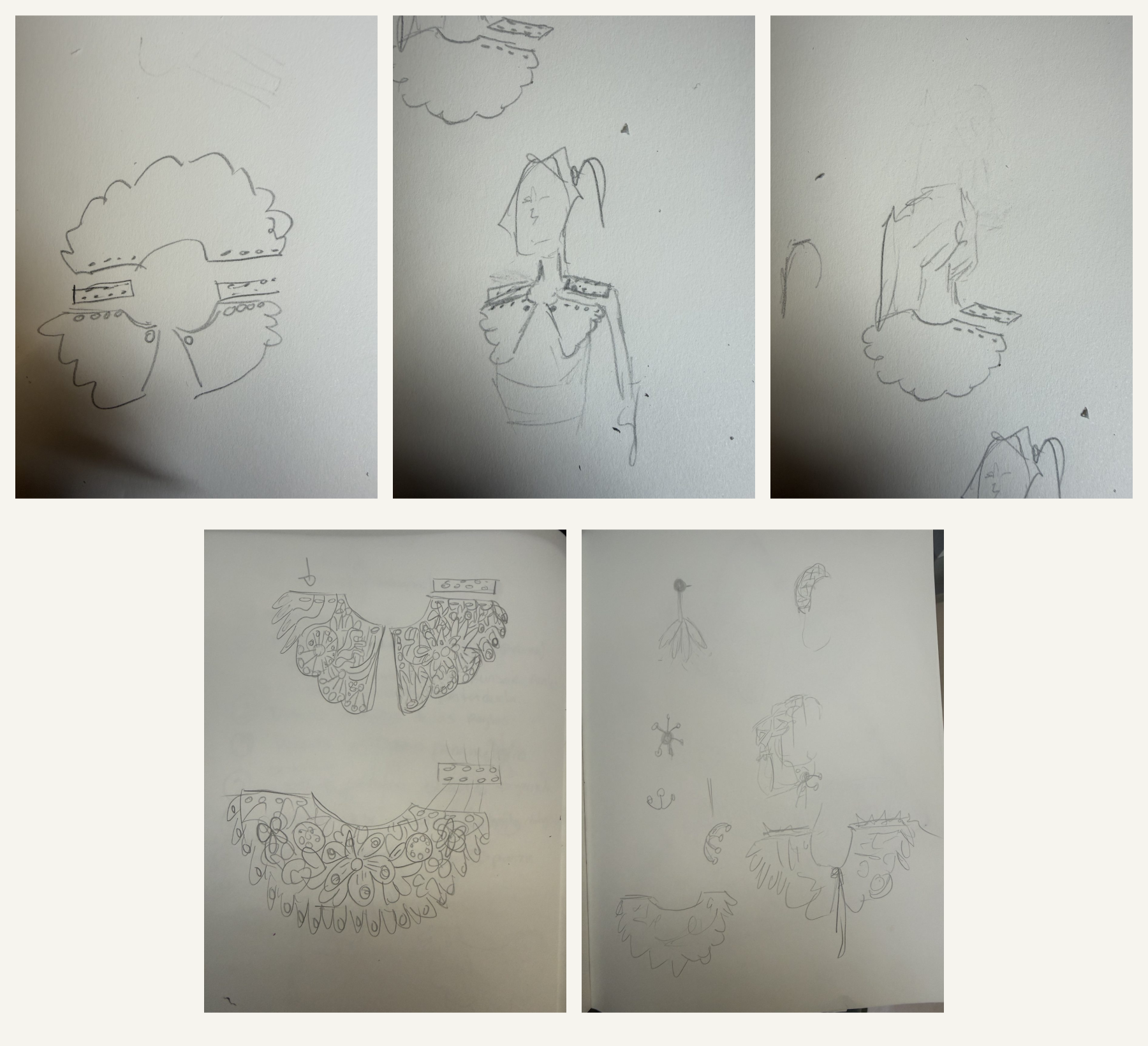
From hand-drawn patterns to printed collar pieces. Following the 2D-to-3D approach introduced in our global masterclass, I developed flat shapes, gave them thickness and relief, and planned to bring them together through traditional assembly.
1. Objective
For this assignment, I wanted to explore how my experience in fashion and textile design could connect with parametric design and 3D printing. My starting point was a set of drawings and a paper prototype of a collar.
The workflow followed what we were taught in the global masterclass: 2D design → 3D thickness and relief → printed pieces → traditional assembly. I developed the pieces as flat patterns, with the intention of joining them with flexible cord. I tested the connections in the paper prototype as part of this approach.
My final files are named T1, T2, F1, F2 and HOMBROS. HOMBROS contains both shoulder pieces. The project combines my drawings and design decisions with guided work in Rhino and Grasshopper, technical assistance from AI, and preparation for fabrication.
2. References, research and inspiration
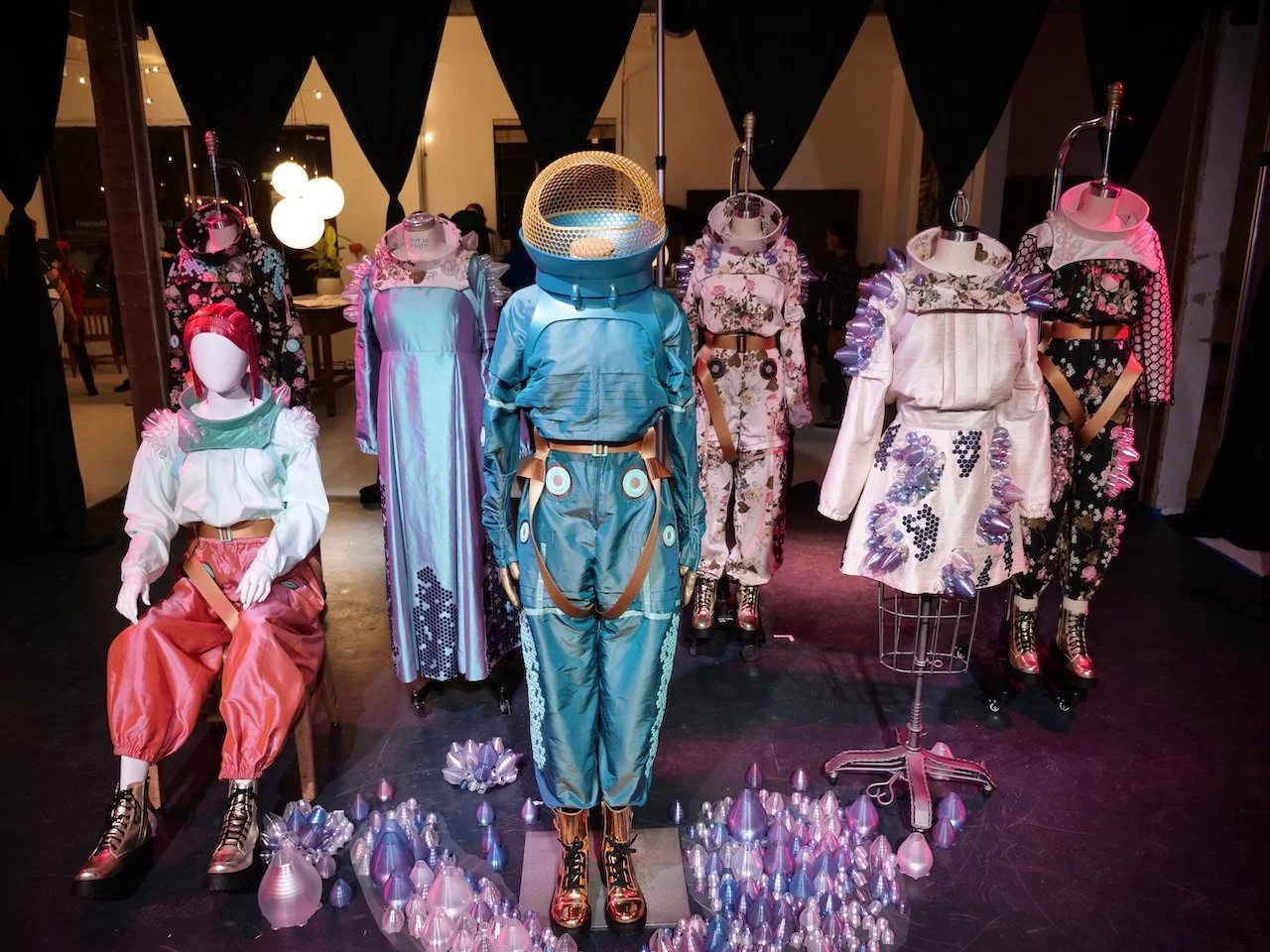
Fashion and 3D fabrication
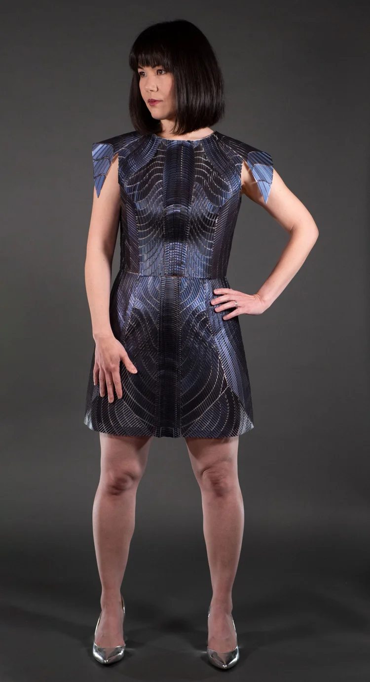
I selected work by two of my students, Lorena Méndez and Pamela Rivas, alongside the work of Sophy Wong.
The look by Lorena Méndez was part of her graduation collection, presented with Ibero CDMX in the context of Paris Fashion Week in October 2026. Pamela Rivas’s images come from her graduation project in December 2025.
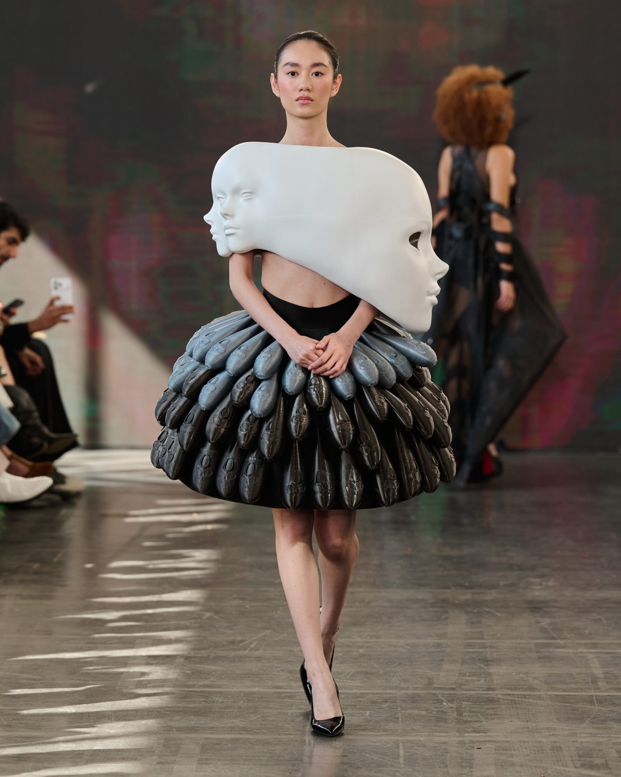
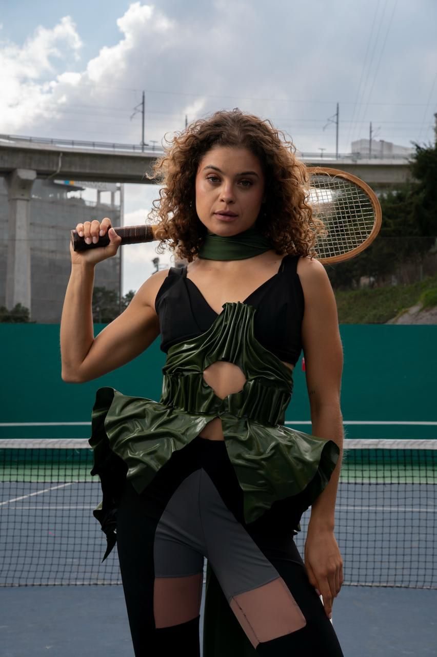
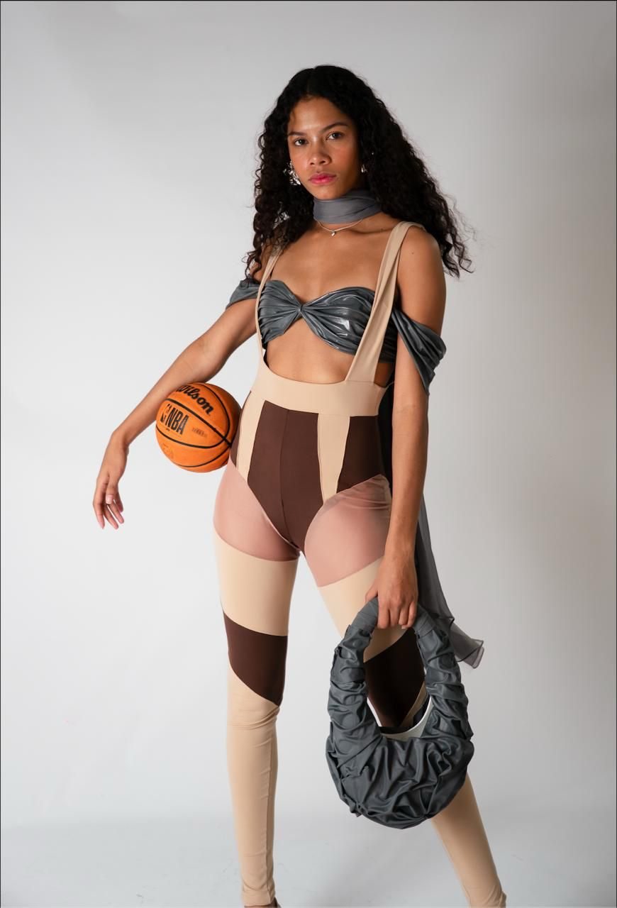
I also selected images from Sophy Wong’s website as references for fashion and digital fabrication.
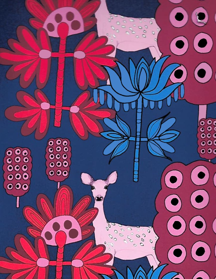
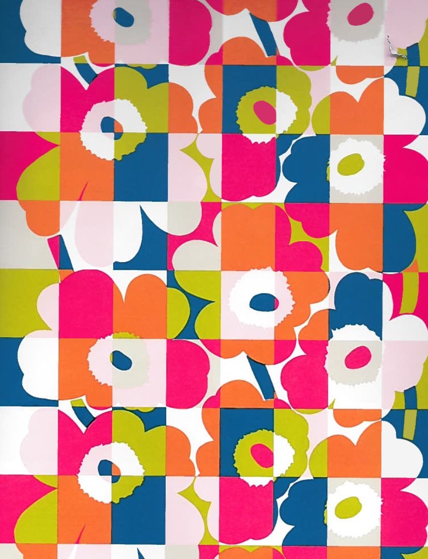
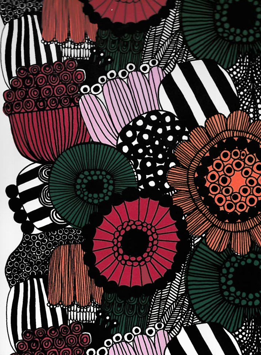
Marimekko and lace
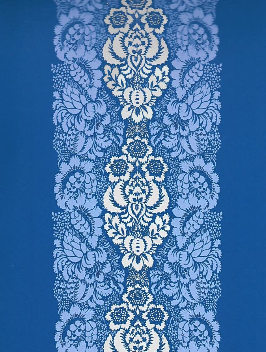
For the motifs, I referred to my physical copy of Marimekko: The Art of Printmaking by Laird Borrelli-Persson. I selected references from pages 37, 69, 124 and 246.
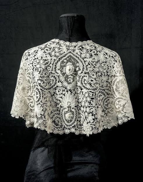
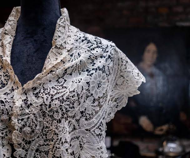
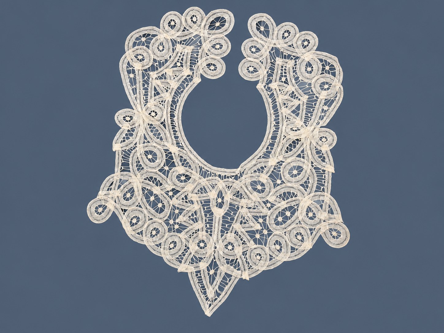
The other important reference was the lace I encountered in Belgium, especially a collar I bought there. I also collected lace images through Google searches, including this Pinterest reference and the article ’t Apostelientje: El templo del Encaje de Brujas by Sara Sáez on Folkmania. These are visual and cultural references; I am not presenting them as scientific sources.
3. Tools and materials
| Stage | Tools or materials |
|---|---|
| Drawing and pattern development | Hand sketches, paper patterns, mannequin and cord |
| Parametric development | Grasshopper, with the geometry displayed in Rhino |
| Drawing and modelling | Rhino; freehand drawing guidance from my mentor Mar |
| Technical assistance | ChatGPT/Codex for explanations, guided steps, diagnosis and some geometry/file preparation |
| Home printing attempt | Longer LK5 Pro, PLA and UltiMaker Cura |
| Current fabrication | Flashforge Adventurer 5M Pro and OrcaSlicer 2.4.2 |
| Loaded filament | Polymaker PolyFlex TPU90, white, 1.75 mm, Shore 90A |
4. Process and workflow
4.1 Hand sketches
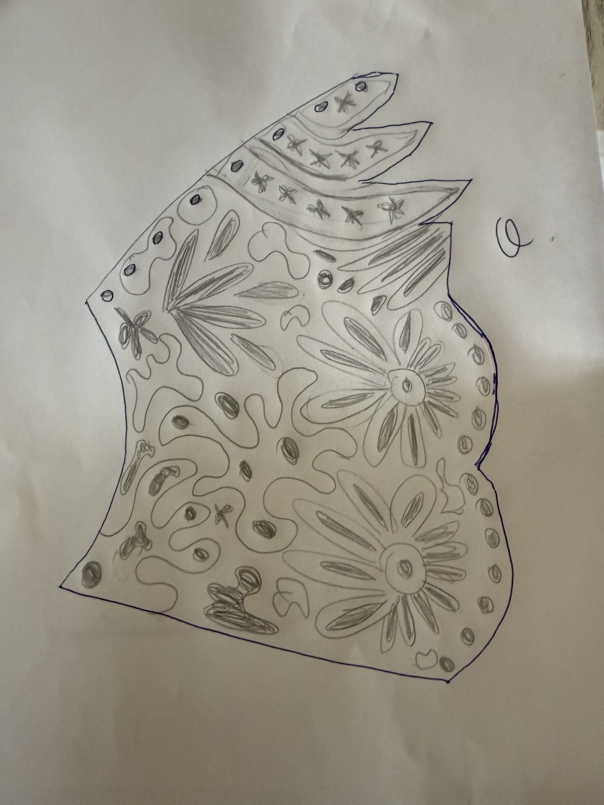
I started by drawing different ideas for the shape of the collar, its motifs and the arrangement of its pieces. These sketches were my starting point for the digital work.
4.2 Paper prototype and pattern making
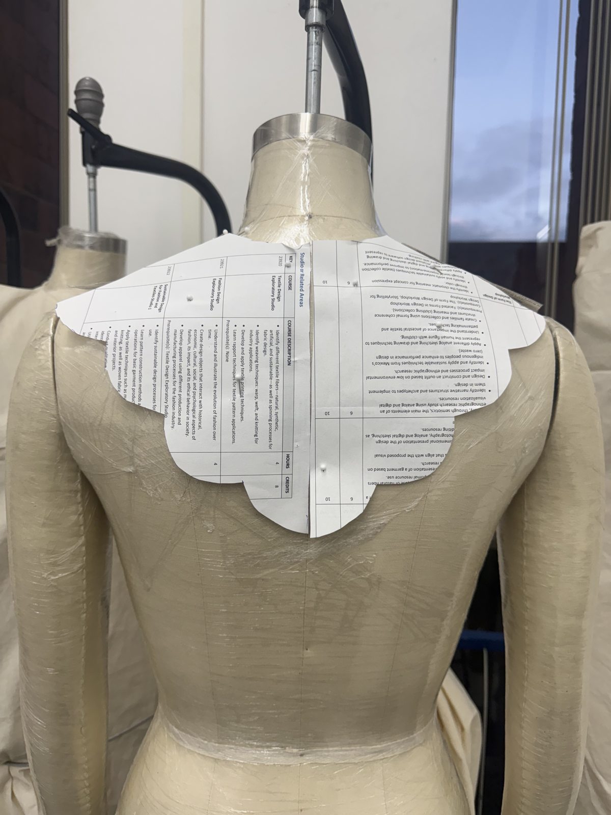
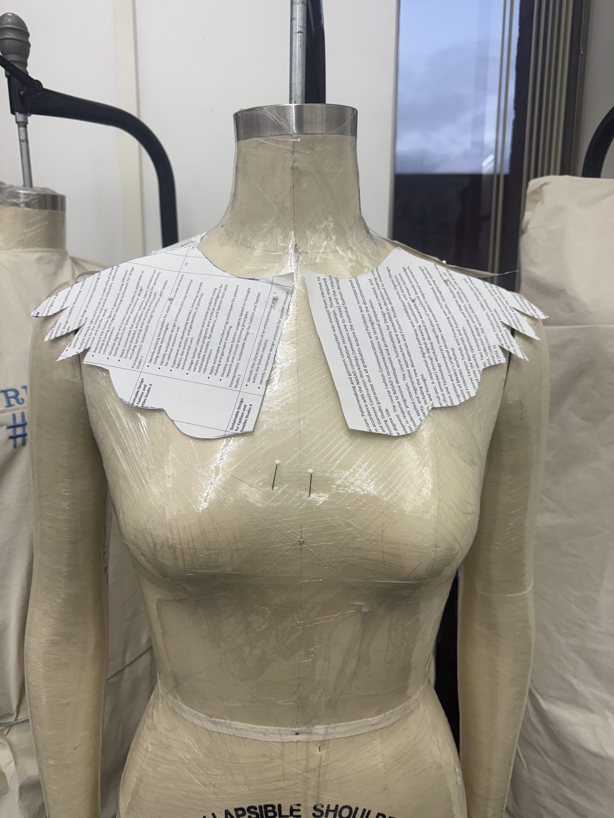
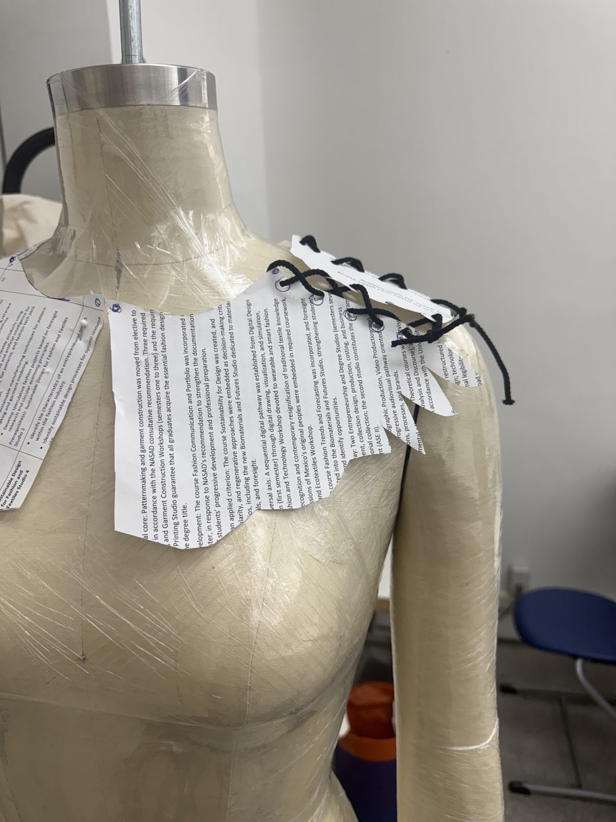
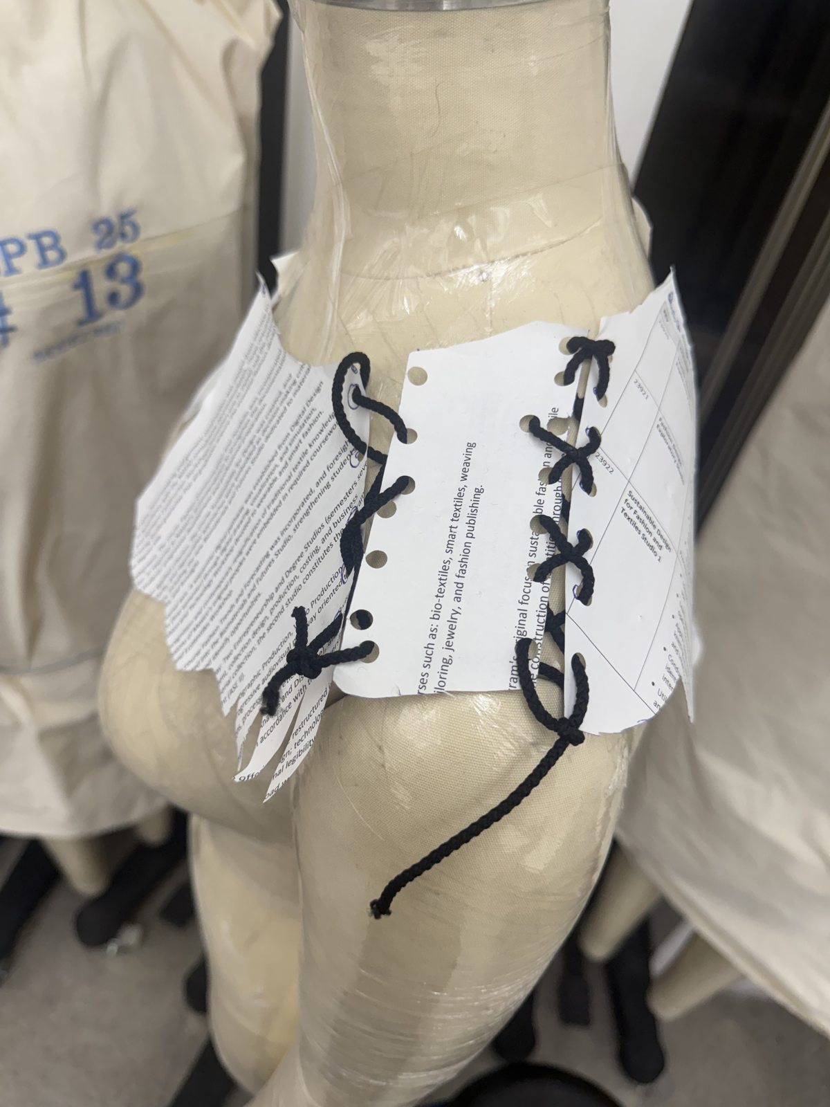
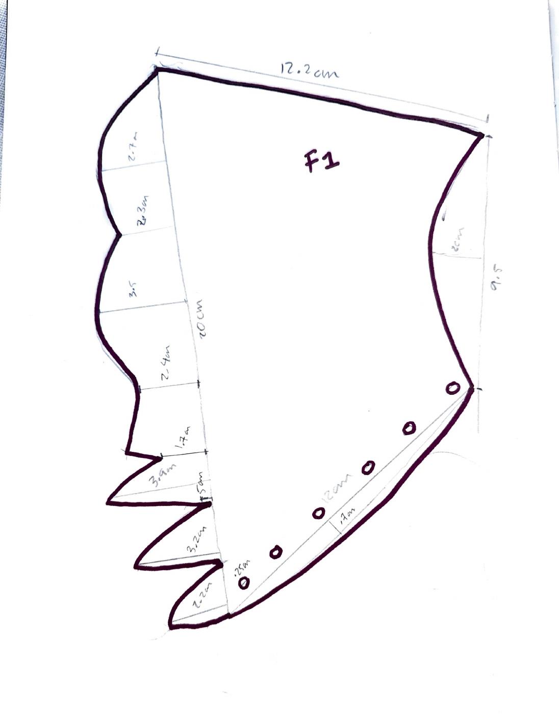
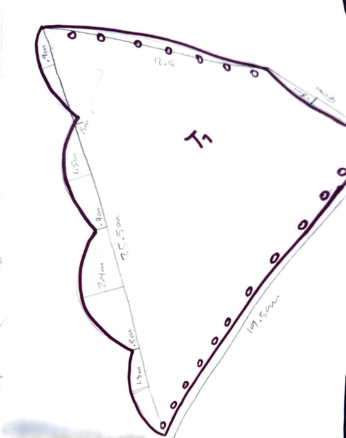
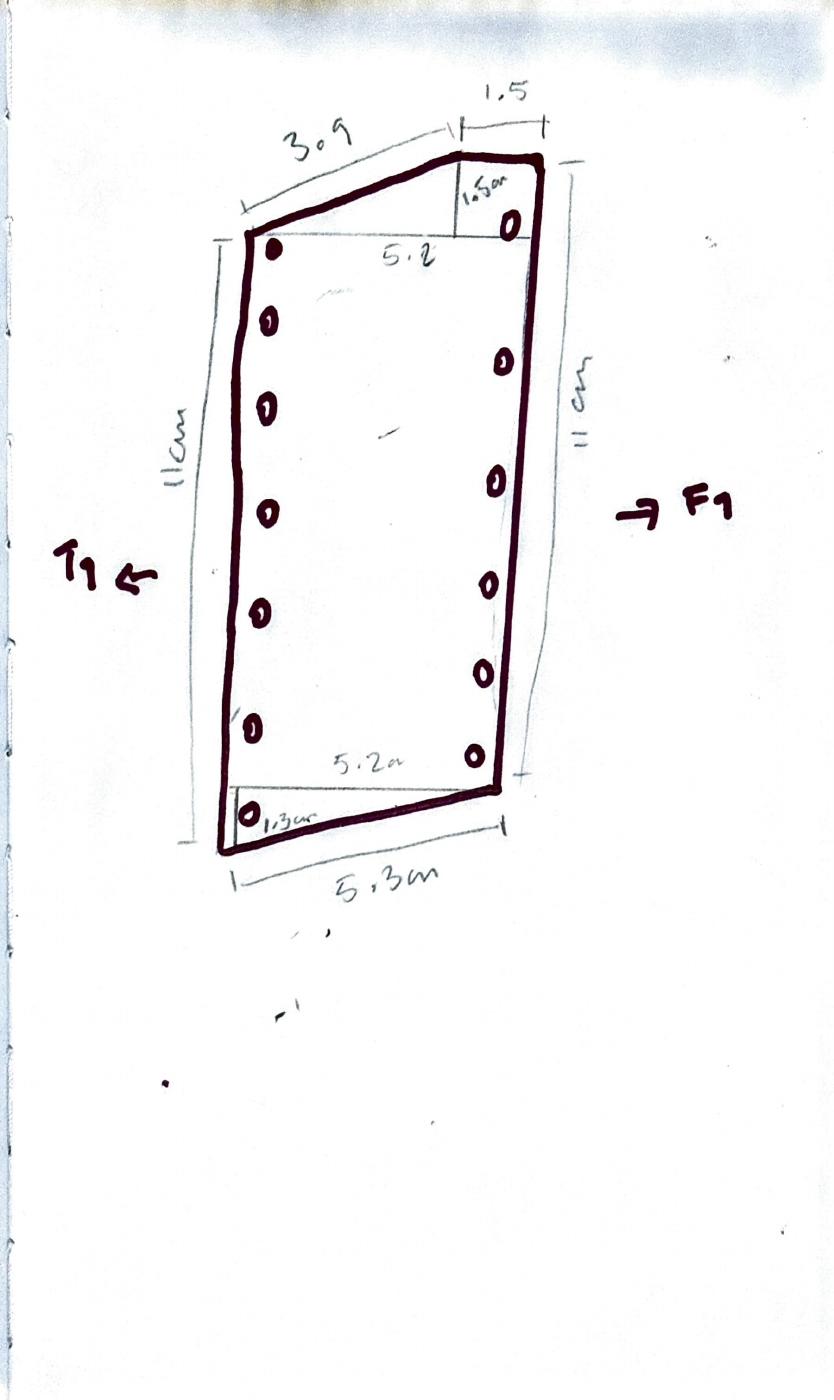
I developed a paper prototype on a mannequin to review the shape and sizes, then drew the patterns. This gave me a way to consider the collar through a familiar fashion-design process before preparing the digital pieces.
I tested laced connections at the shoulders of the paper prototype. The final printed pieces are intended to use flexible cord for traditional assembly.
View the scanned patterns
4.3 Developing the T1 outline in Grasshopper
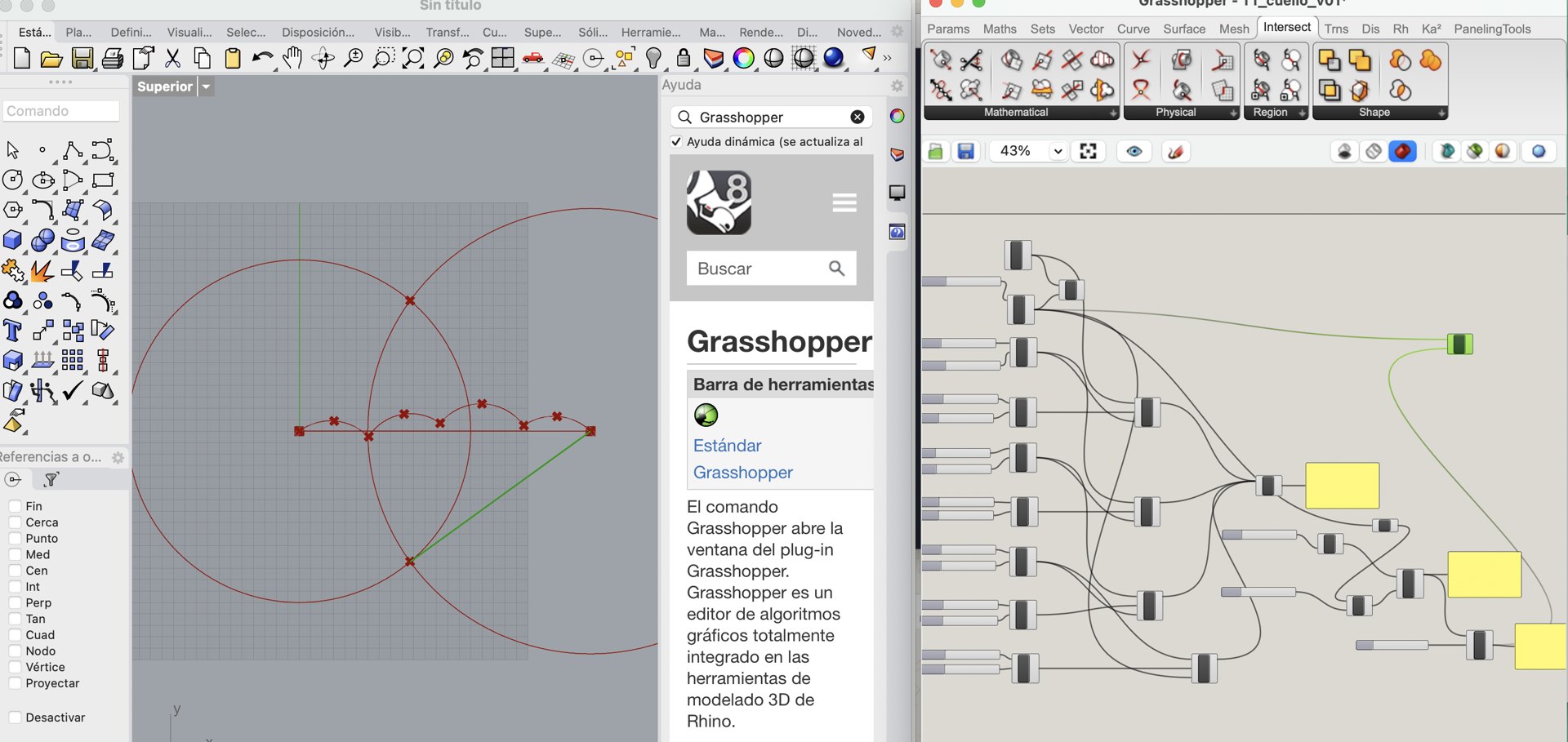
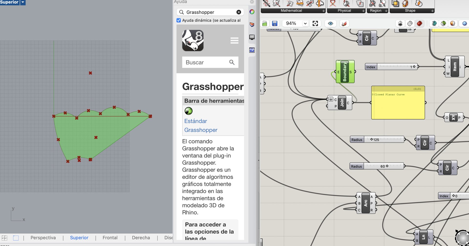
I worked on the outline of T1 in Grasshopper with step-by-step guidance. I approached this as a form of pattern making using parametric design: entering numerical values, connecting elements and observing how the shape changed in Rhino.
I learned how to connect components, enter numerical values and adjust parameters to change the shape. This introduced me to a different way of approaching patternmaking, where dimensions and relationships can be adjusted through connected elements.
4.4 Drawing the motifs in Rhino
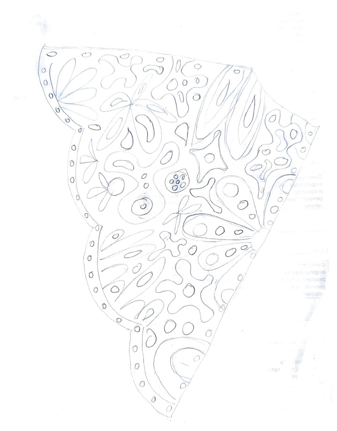
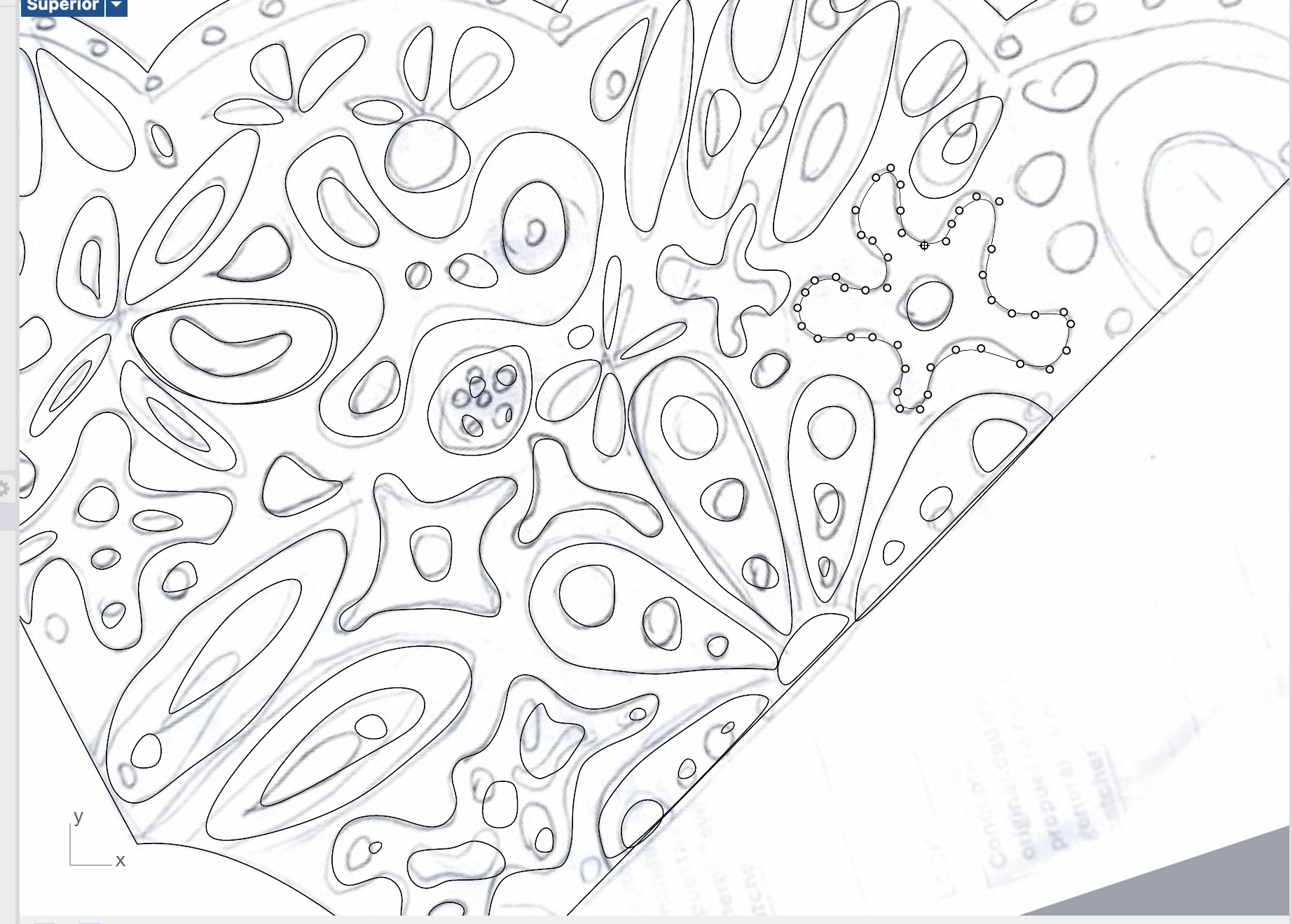
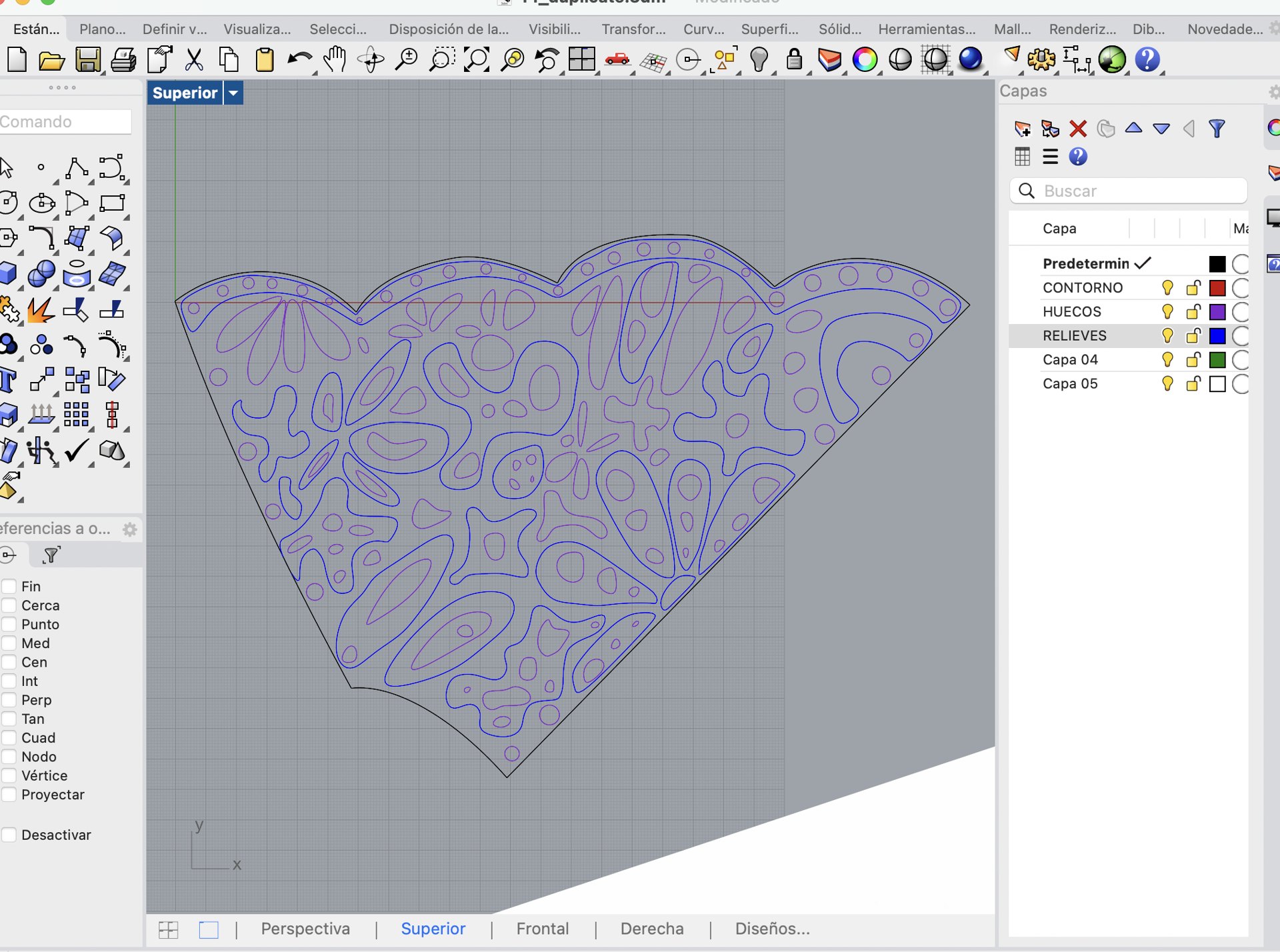
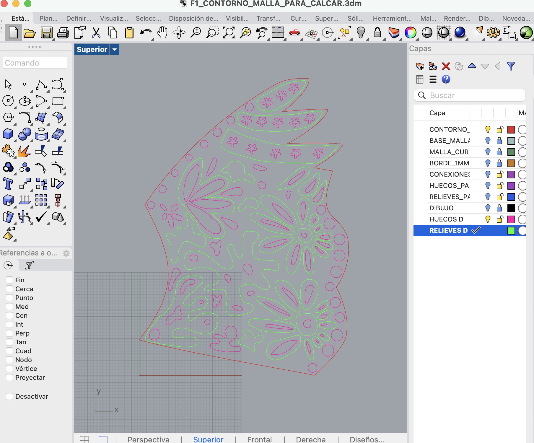
I drew the decorative curves in Rhino from my hand-drawn designs. Mar, my mentor, supported me throughout the process and taught me how to use Rhino’s freehand drawing tools.
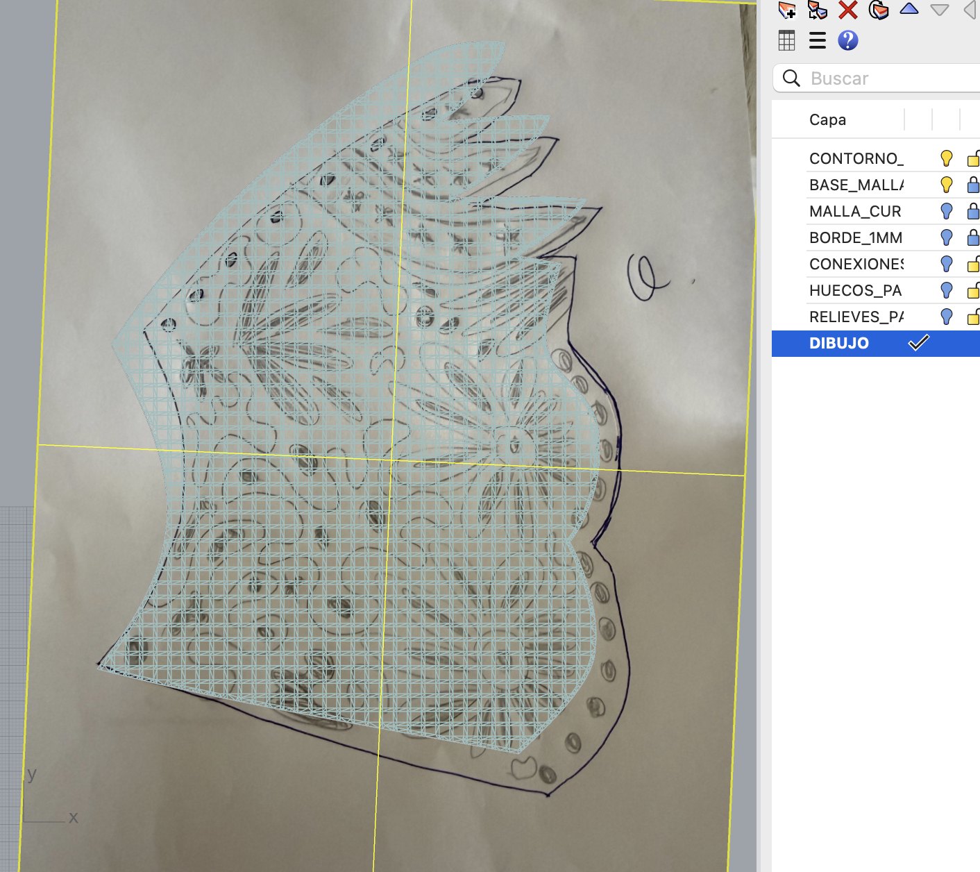
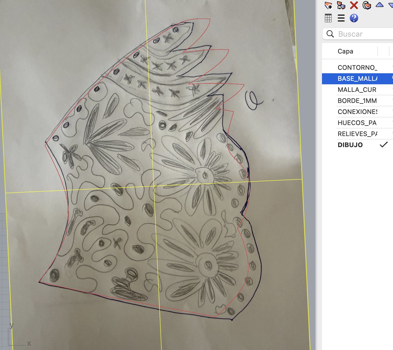
For F1, I placed my drawing as a reference image and traced my own cut-out and relief curves on separate layers. I also drew the decorative perforations for the shoulders and decided to keep those pieces without relief.
Placing and aligning the F1 reference
4.5 From 2D curves to printable 3D pieces
The next step was to turn the flat design into pieces with thickness, cut-outs and raised motifs. I defined the base thickness, the total height of the decorated areas, the borders, the connections and the simplification of the design.
T2 and F2 are mirrored versions of T1 and F1. This was still a pattern-based workflow: the pieces were prepared flat for printing, with the collar’s assembled form to be created afterwards through its connections.
| Model parameter | Value | Meaning |
|---|---|---|
| Base thickness | 0.8 mm | Designed thickness |
| Decorated areas | 2 mm total height | 1.2 mm above the 0.8 mm base |
| Borders | 1 mm wide | Width, not height |
| Shoulders | 0.8 mm; no relief | Decorative perforations only |
| Assembly | Flexible cord | Laced connections tested on the paper prototype |
4.6 Geometry problems and changes
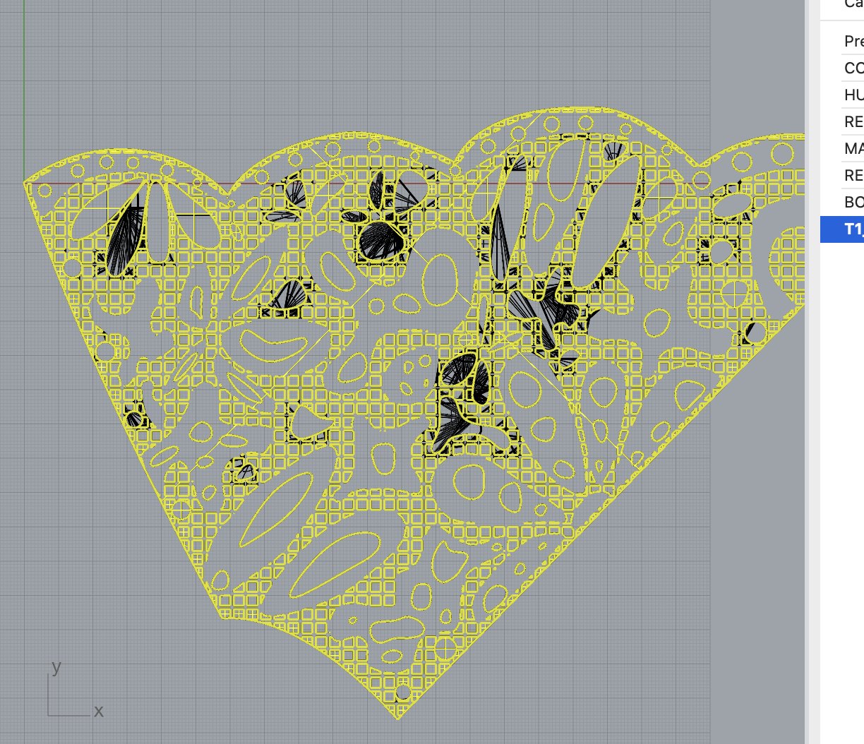
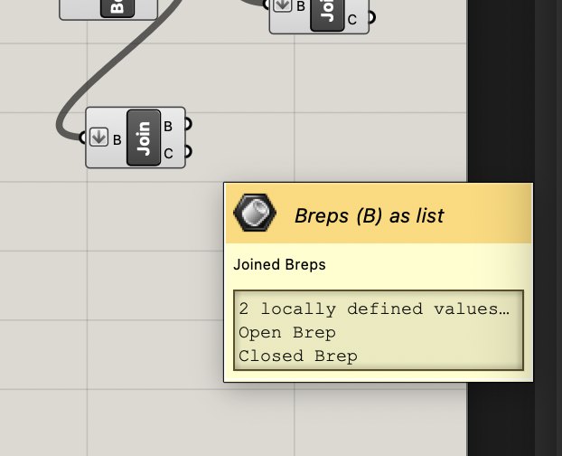
Developing T1 was not straightforward. Some attempts to give the geometry thickness produced open surfaces and curves that needed correction.
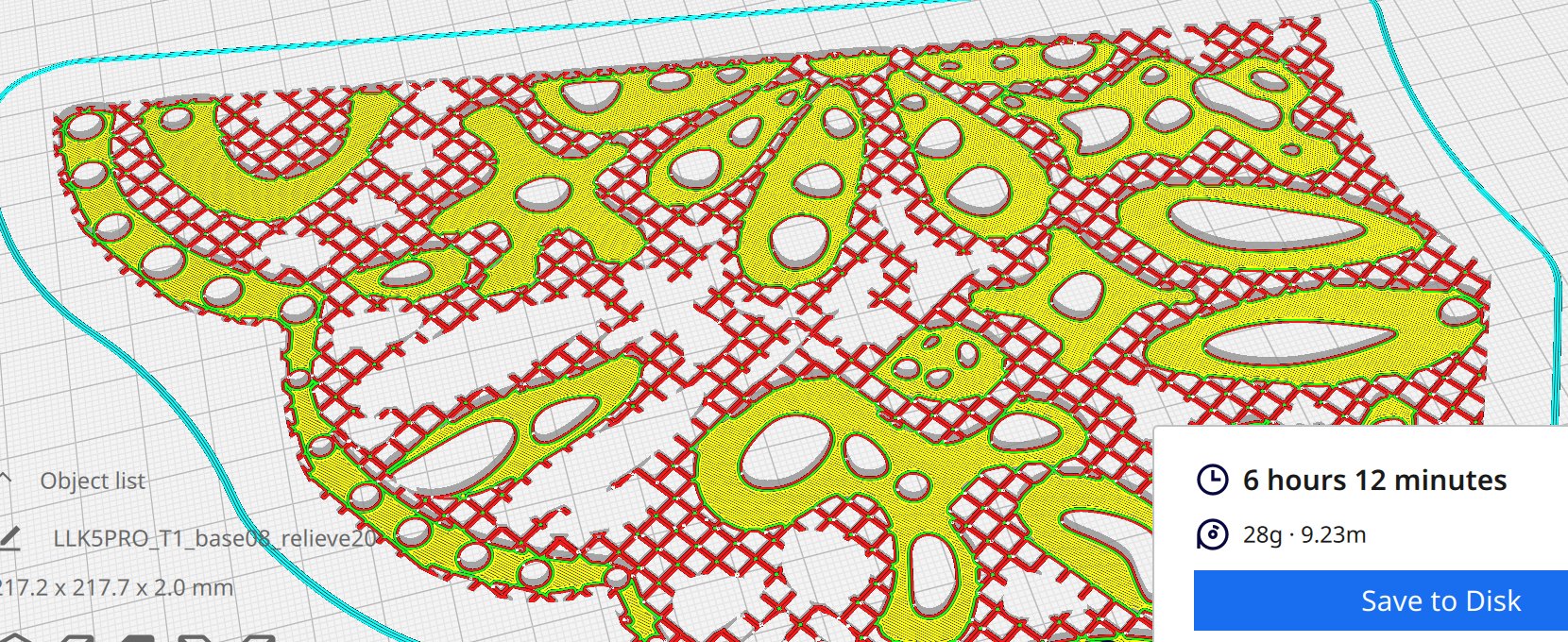
When reviewing an earlier version in Cura, I noticed problems along the contours. Continuous borders were added around the cut-outs and the outside of the pattern with AI assistance. I also simplified the shoulders by keeping the holes I had drawn without adding relief.
4.7 Unsuccessful PLA attempt at home
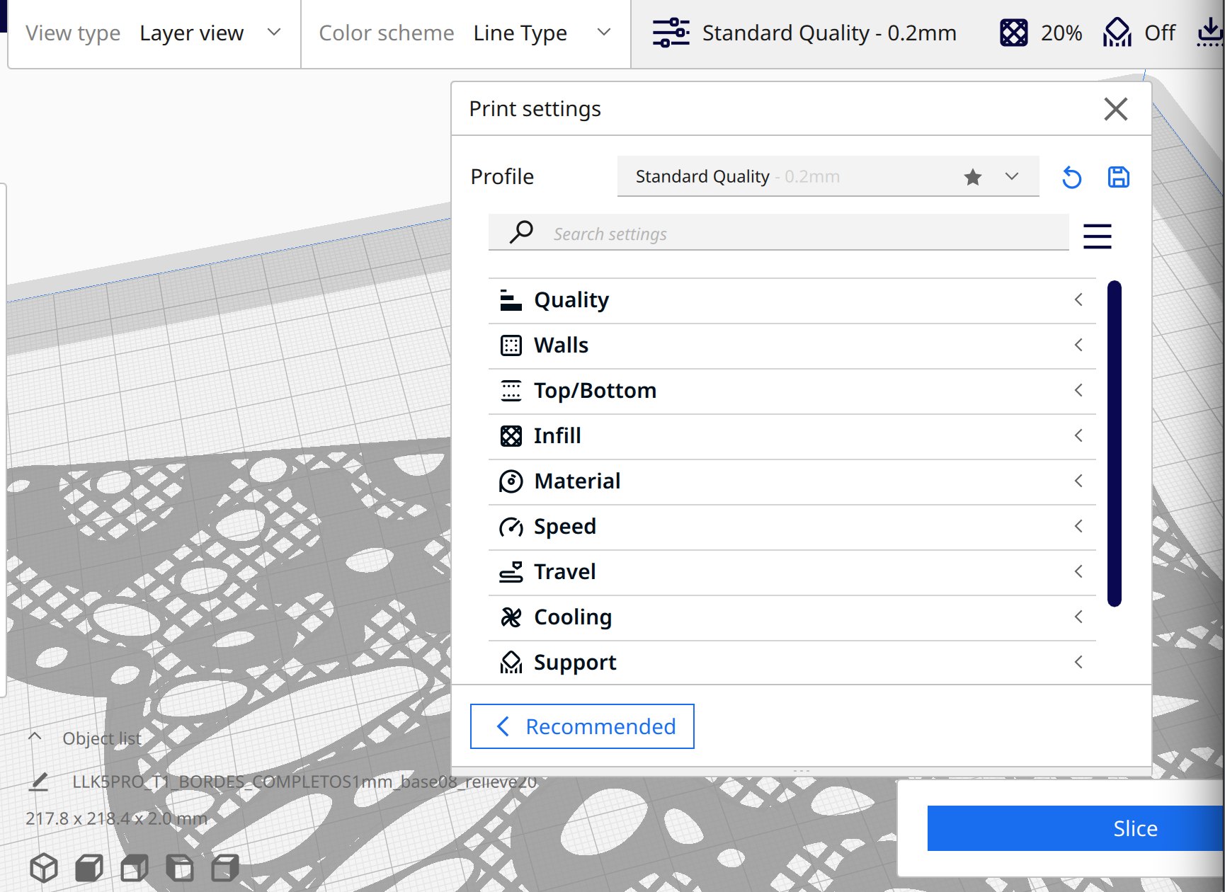
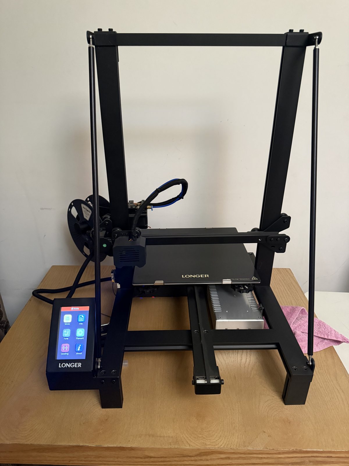
I installed UltiMaker Cura and prepared a print on my Longer LK5 Pro at home. I did not obtain a usable result: the PLA was coming out badly. I suspected that the material might have been old, and the printer had not been used for a long time. I did not establish the cause, so I am recording these as possible explanations rather than a confirmed diagnosis.
4.8 Preparing the pieces in OrcaSlicer
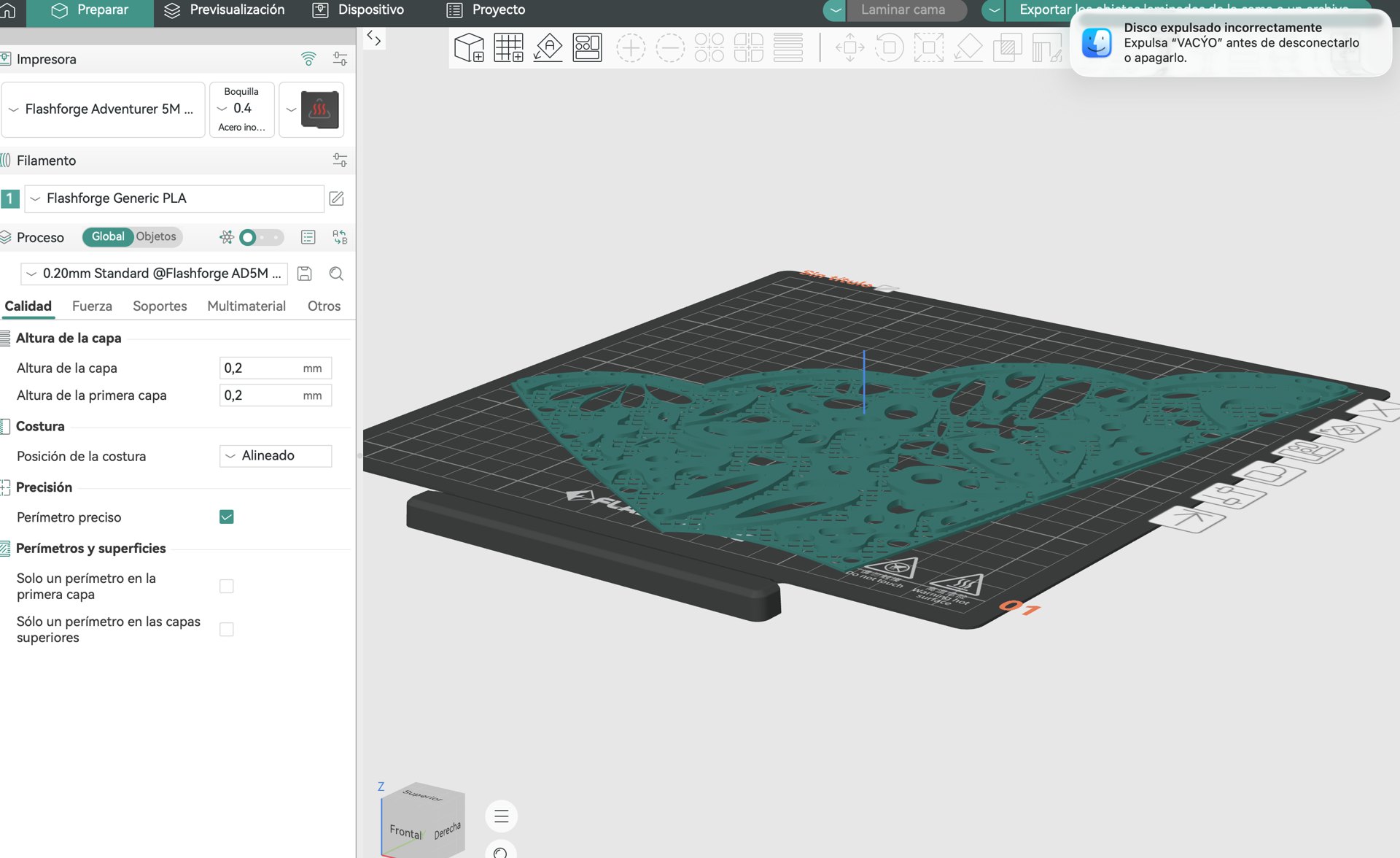
I then installed OrcaSlicer and prepared the pieces for the Flashforge Adventurer 5M Pro. I worked with the STL files, reviewed the pieces in the slicer and prepared the G-code.
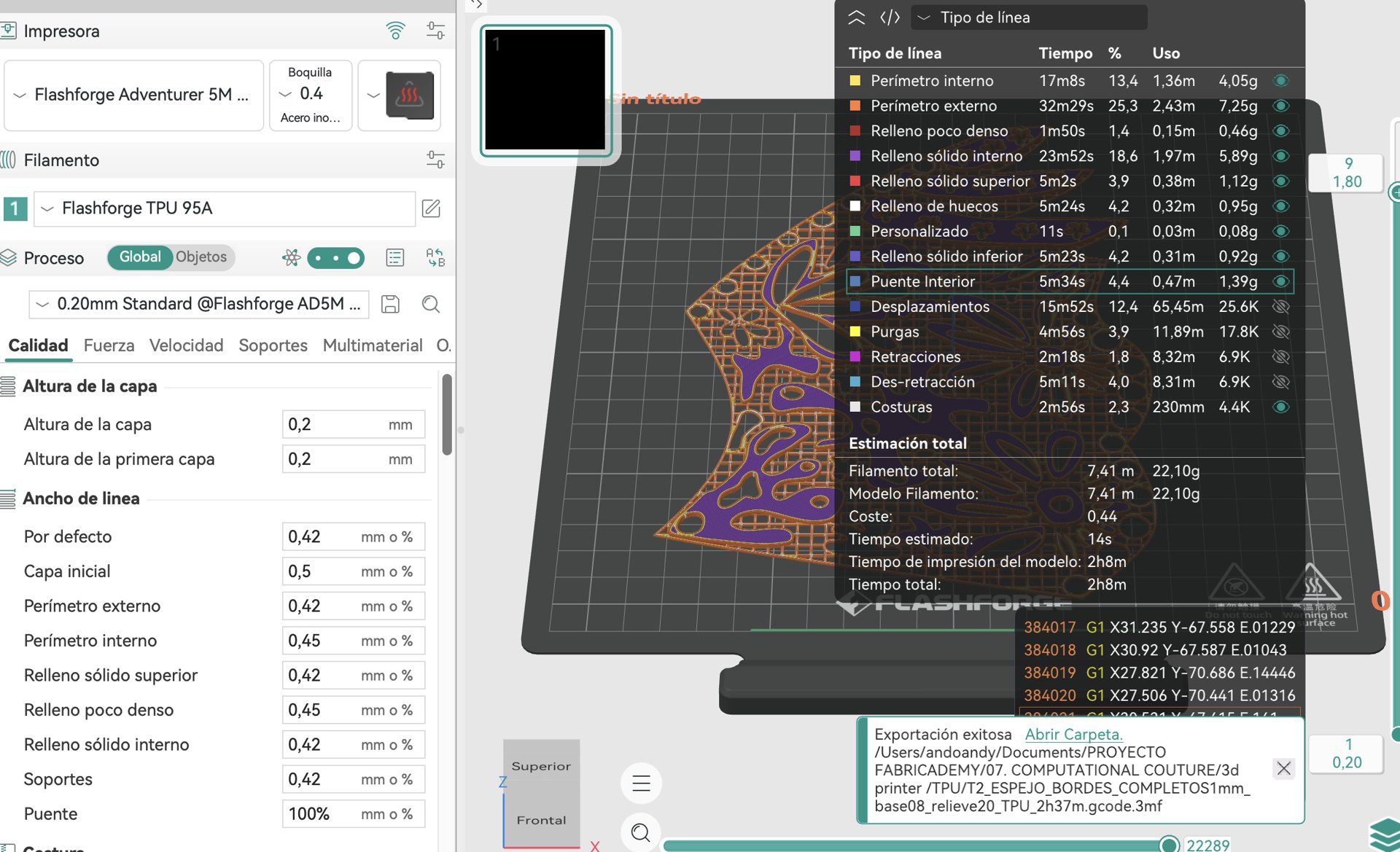
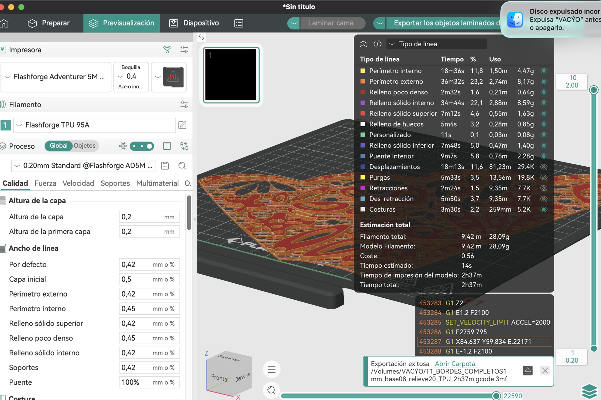
The material loaded in the printer is the white Polymaker PolyFlex TPU90 shown in my photographs. The saved slicer preset is named Flashforge TPU 95A. These are different: one identifies the actual filament, while the other is the preset used to prepare the files.
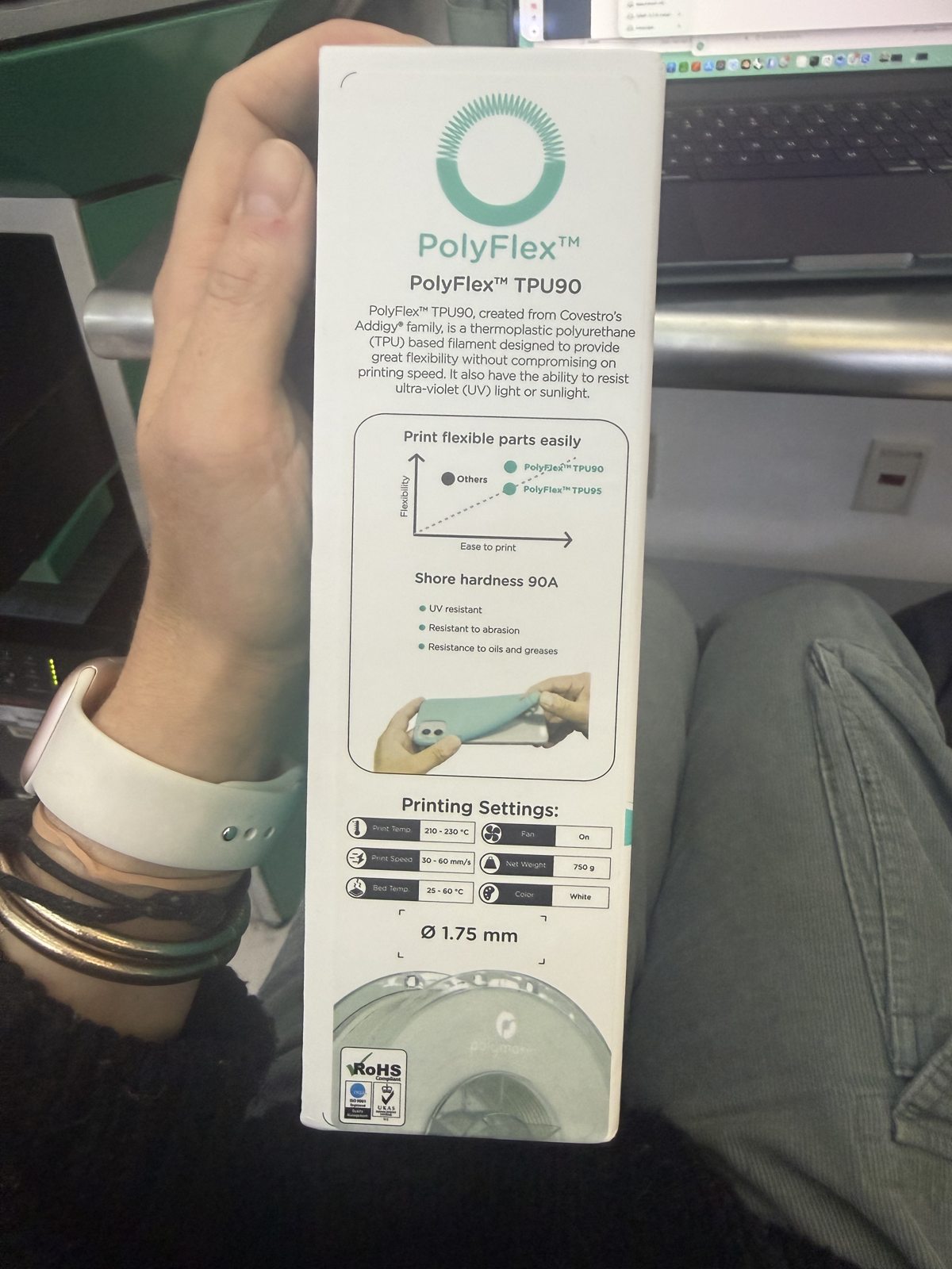
Material information from the photographed packaging
| Manufacturer’s label | Value |
|---|---|
| Material / hardness | PolyFlex TPU90 / Shore 90A |
| Diameter / colour | 1.75 mm / white |
| Suggested nozzle temperature | 210–230 °C |
| Suggested bed temperature | 25–60 °C |
| Suggested printing speed | 30–60 mm/s |
| Cooling fan | On |
These are the manufacturer’s recommendations printed on the packaging, not measured values from my prints.
Saved slicing and machine settings
I prepared the pieces in OrcaSlicer using the Flashforge Adventurer 5M Pro profile and printed with white PolyFlex TPU90. The table records the settings saved in my G-code files and explains their role in this project. I worked from a slicer preset with technical guidance; these values are not the results of a separate calibration study.
| Parameter | Recorded value | Role in this print |
|---|---|---|
| Printer profile / slicer | Flashforge Adventurer 5M Pro / OrcaSlicer 2.4.2 | These identify the machine profile and software used to prepare the files. |
| Nozzle diameter in profile | 0.4 mm | This is the nozzle diameter recorded in all five saved G-code files. |
| Filament preset / loaded material | Flashforge TPU 95A / white PolyFlex TPU90 | I used this preset with my PolyFlex TPU90 roll. The preset name and the material’s hardness are different; the values below record the setup I used. |
| Nozzle / bed temperature | 225 °C / 45 °C | Both values fall within the ranges printed on my filament label. The nozzle heats the filament for extrusion, while the heated bed supports first-layer adhesion. |
| Layer height / first layer | 0.2 mm / 0.2 mm | This is half the profile’s nozzle diameter, a practical starting point that balances vertical detail and printing time. At this layer height, the 0.8 mm base corresponds to four layers and the 2 mm decorated areas to ten. |
| Wall loops | 2 | These define the perimeters around the outlines and openings. The slicer determines how the paths fit into narrow features. |
| Top / bottom shell layers | 5 / 3 | These settings define solid surface layers. In the thin base, the top and bottom regions can overlap, leaving no separate sparse-infill region. |
| Nominal infill | 15% | This applies where there is room for sparse internal filling. It does not describe the density of every feature, and the decorative openings are part of the model geometry. |
| Supports / brim | Disabled / no brim | The pieces were prepared flat on the build plate. The saved setup uses no support structures or additional brim around the edges. |
| Retraction | 0.8 mm at 35 mm/s | Retraction pulls filament back during travel to help reduce oozing. These are the saved settings; some fine strings remained visible on the printed pieces. |
| Maximum volumetric flow | 3.5 mm³/s | This limits how much material the slicer requests per second and can reduce extrusion speeds below the speed values listed below. |
| First-layer wall / infill speeds | 50 / 80 mm/s | These configured speeds are lower than the later-layer values, giving the first layer a slower starting setting. The volumetric-flow limit also applies. |
| Outer / inner wall speeds | 200 / 300 mm/s | These are configured speed limits, not measured printing speeds. The flow limit and machine acceleration constrain the generated motion. |
| Infill / travel speeds | 270 / 500 mm/s | The first value is a configured extrusion speed, subject to the flow limit. Travel is movement without extrusion and is governed by motion limits rather than material flow. |
| Minimum / maximum fan settings | 100 / 100% | The saved cooling settings use full fan speed, consistent with the filament label’s instruction to use cooling. These two values alone do not describe every first-layer or special-feature fan rule. |
Technical references for the explanations: Prusa — Layers and perimeters and OrcaSlicer — Maximum volumetric speed.
Model dimensions and printing time
| STL file | X × Y × Z extent (mm) |
|---|---|
| T1.stl | 217.784 × 218.395 × 2.000 |
| T2.stl | 217.784 × 218.395 × 2.000 |
| F1.stl | 142.563 × 201.894 × 2.000 |
| F2.stl | 142.563 × 201.894 × 2.000 |
| HOMBROS.stl | 114.000 × 123.000 × 0.800 |
Model dimensions from the final STL files. HOMBROS contains both shoulder pieces.
| G-code file | Estimated time | Estimated material |
|---|---|---|
| T1_TPU_2h37m.gcode | 2h 37m 19s | 28.09 g |
| T2_TPU_2h37m.gcode | 2h 37m 27s | 28.09 g |
| F1_TPU_2h8m.gcode | 2h 8m 11s | 22.10 g |
| HOMBROS_TPU_37m48s.gcode | 37m 48s | 4.75 g |
| F2_TPU_2h8m.gcode | 2h 8m 18s | 22.09 g |
The times and masses are slicer estimates based on the selected profile. They are separate from measured printing time, material use and physical dimensions.
5. Results and assembly
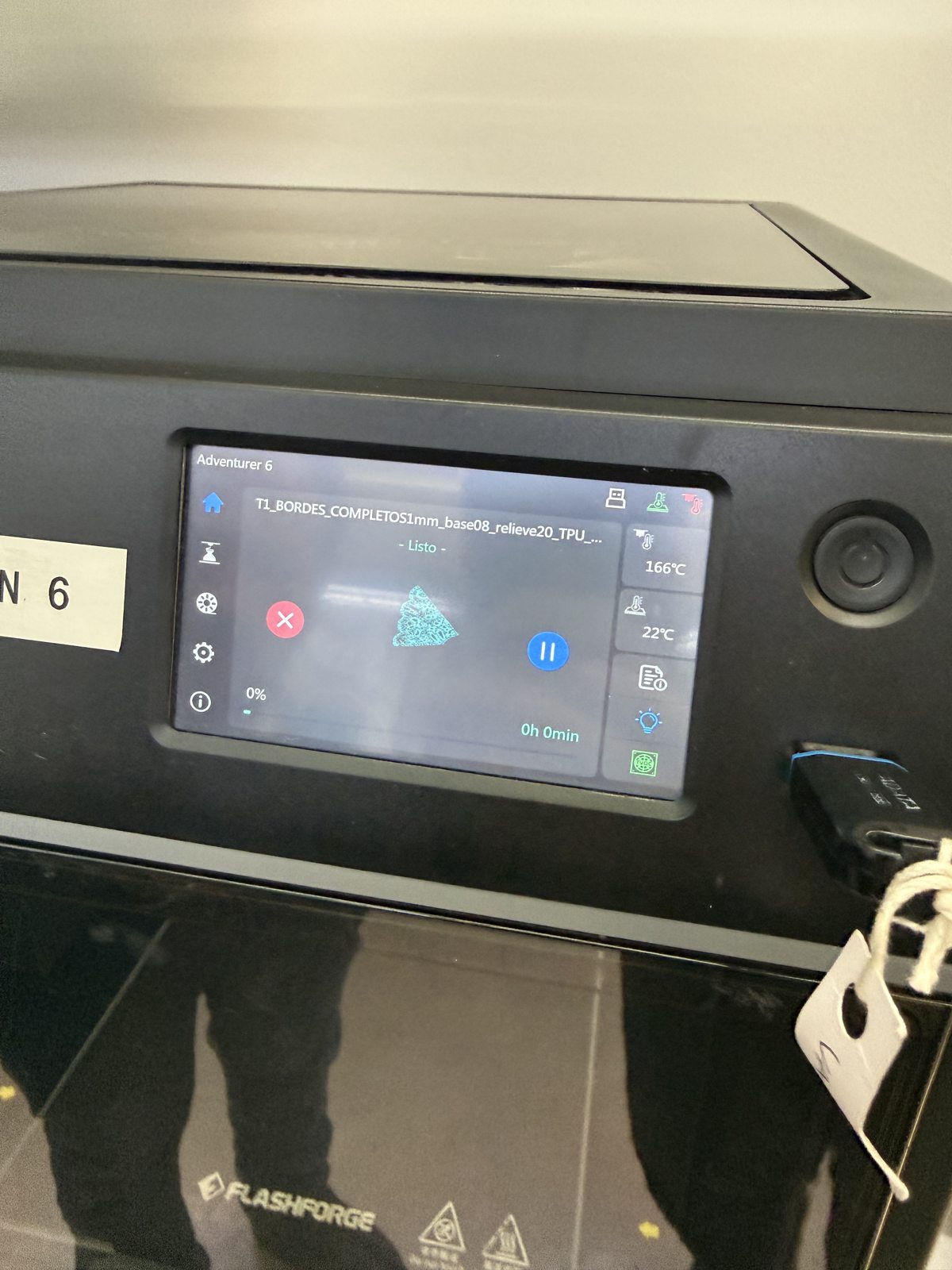
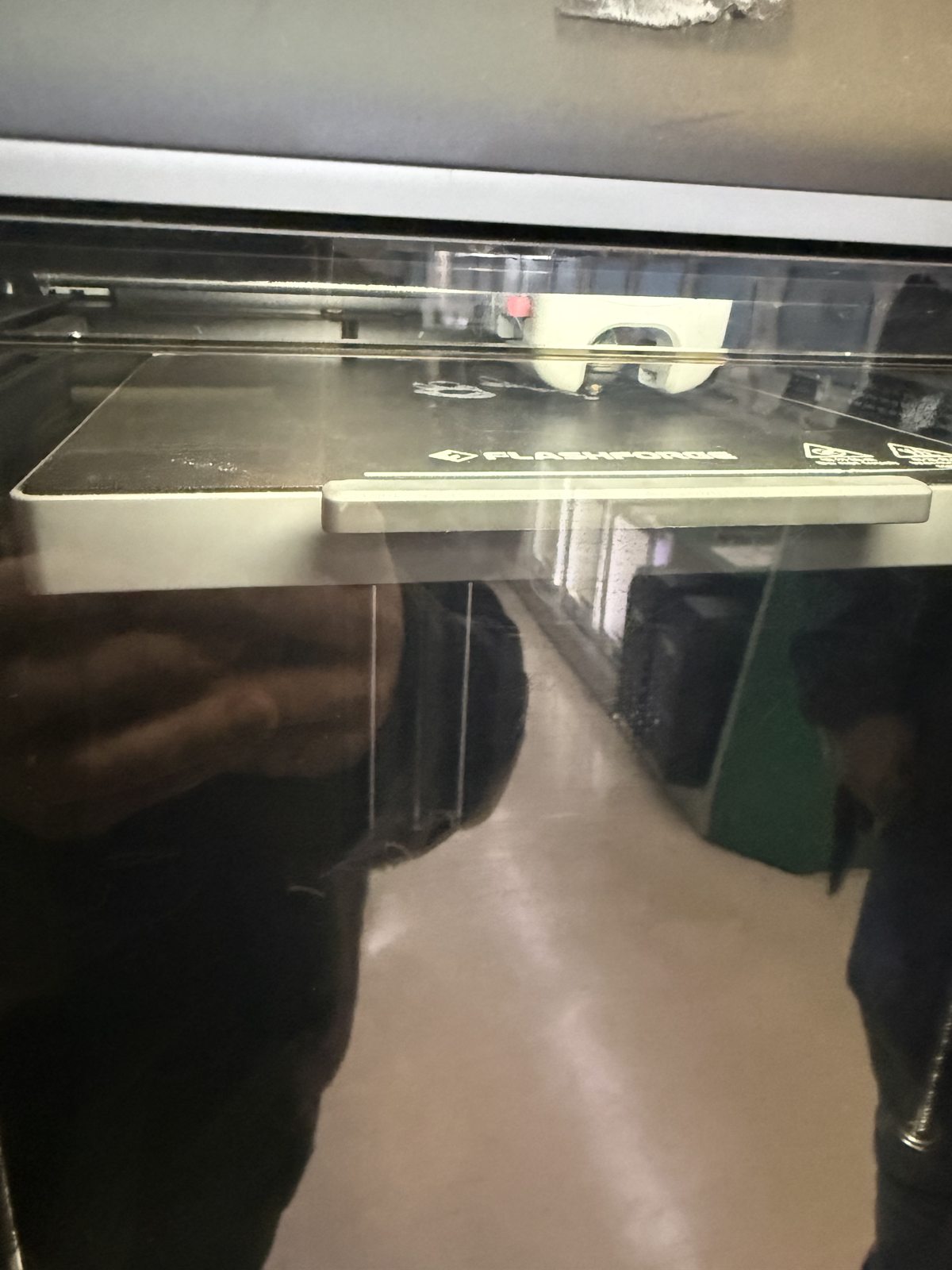
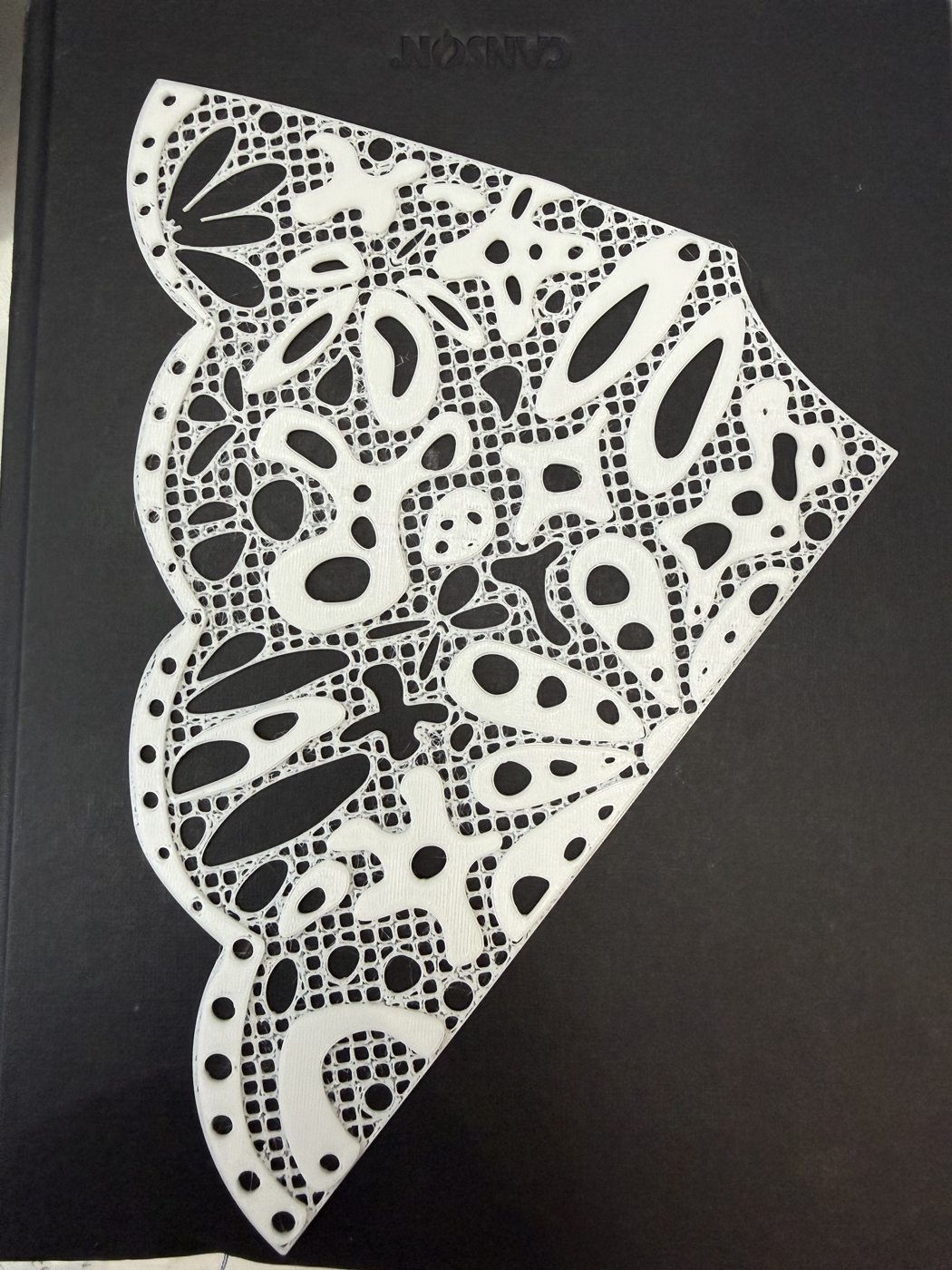
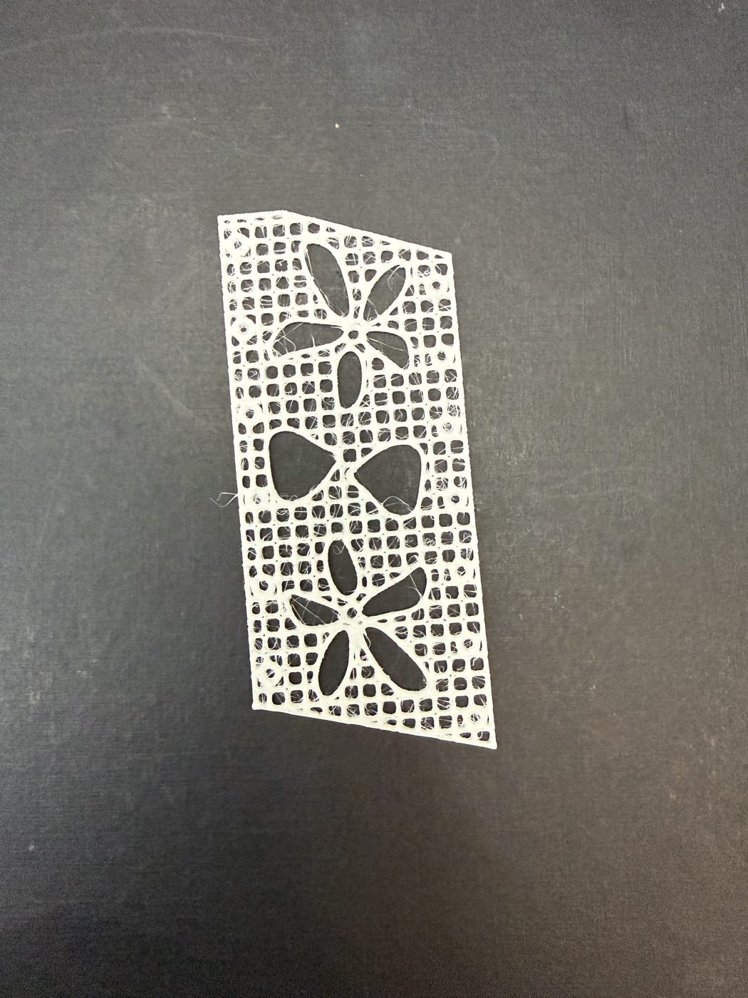
I used the Flashforge Adventurer 5M Pro and white PolyFlex TPU90 to print the collar pieces.
The paper prototype shows the laced construction developed for this 2D-to-3D workflow.
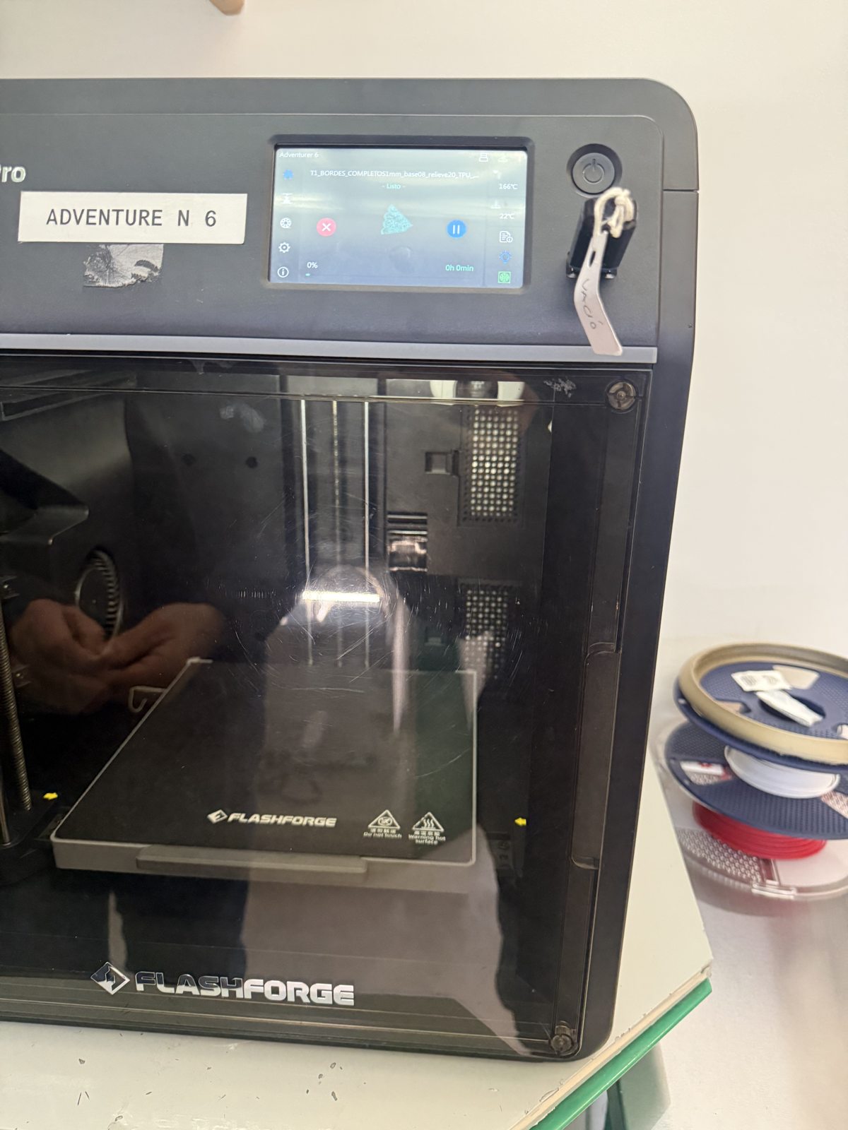
Final printed pieces and assembly
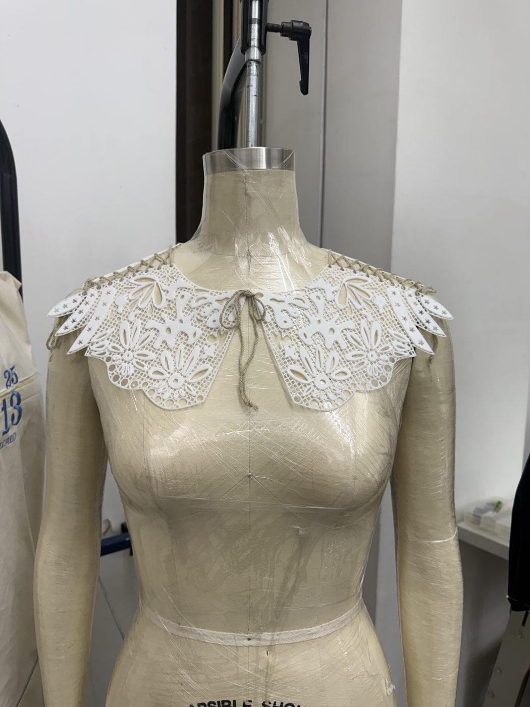
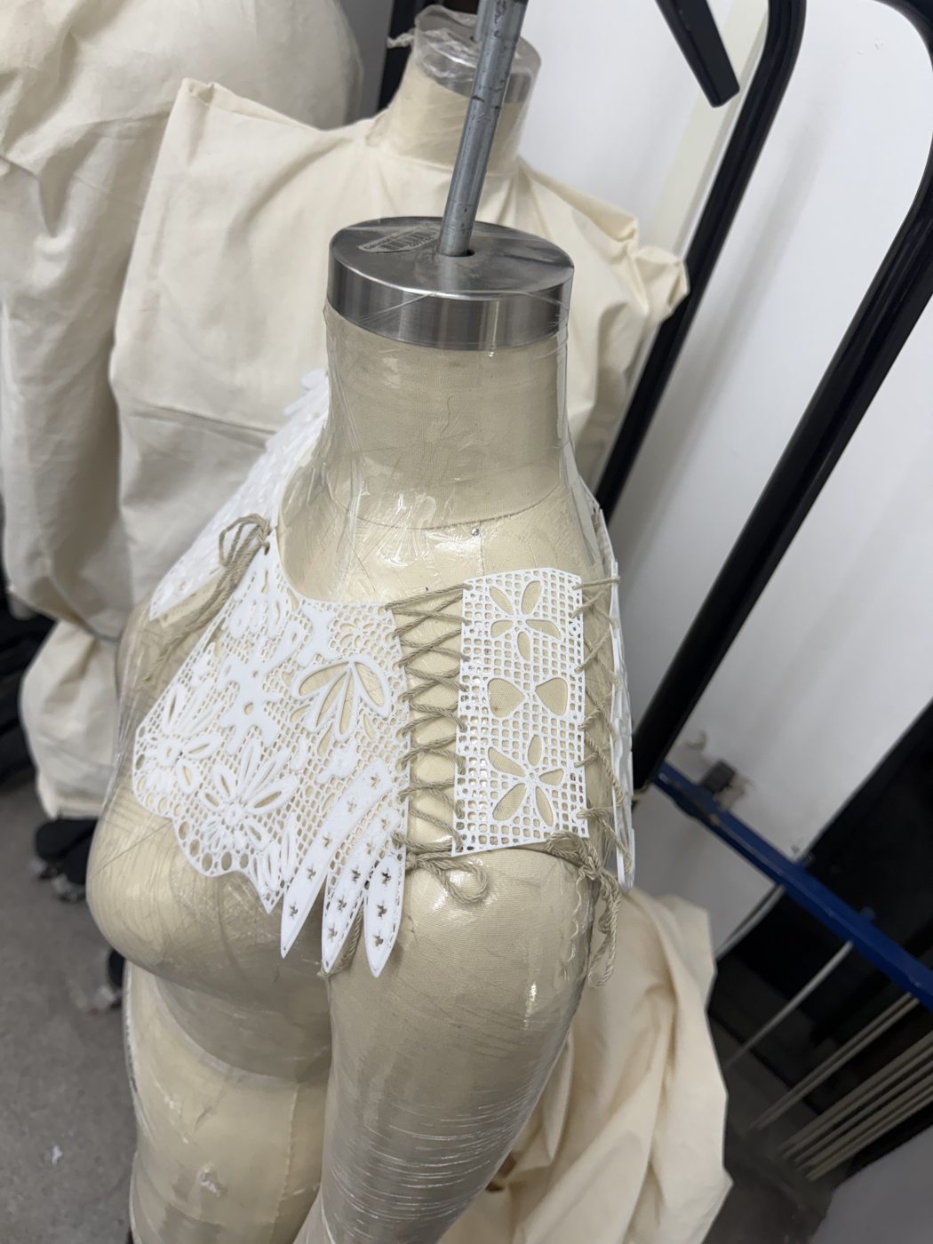
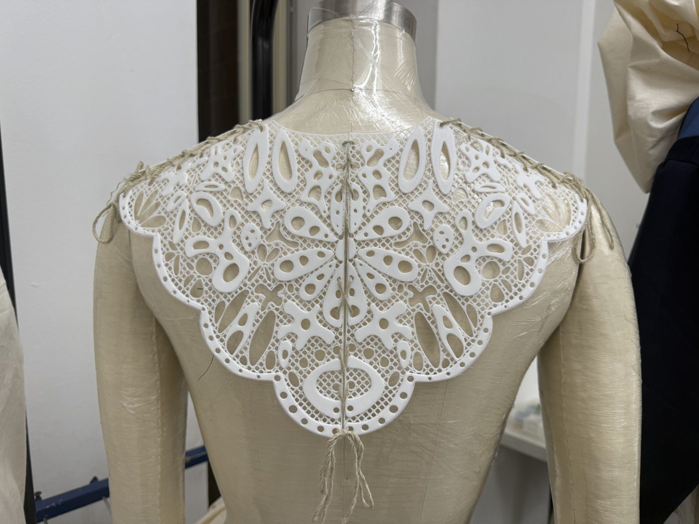
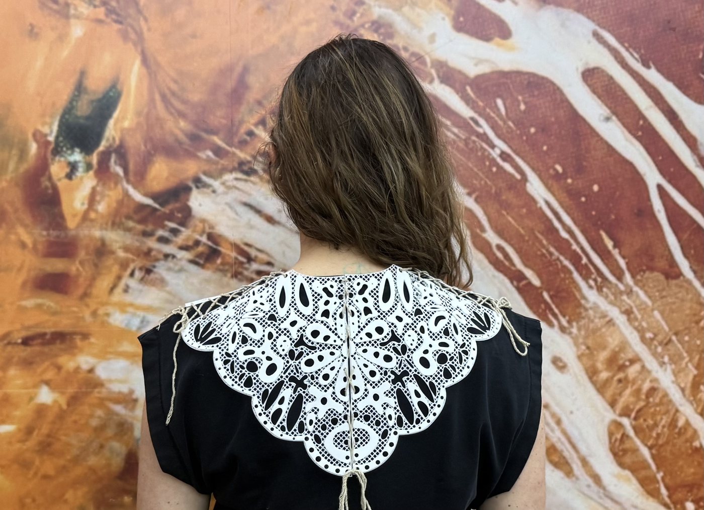
I completed the collar in white PolyFlex TPU90 and assembled the printed pieces with cord threaded through the connection holes. The photographs show the front, back and shoulder connections on the mannequin. This completed the approach I followed from the global masterclass: working from 2D patterns, adding thickness and relief for printing, and using traditional assembly to bring the pieces together.
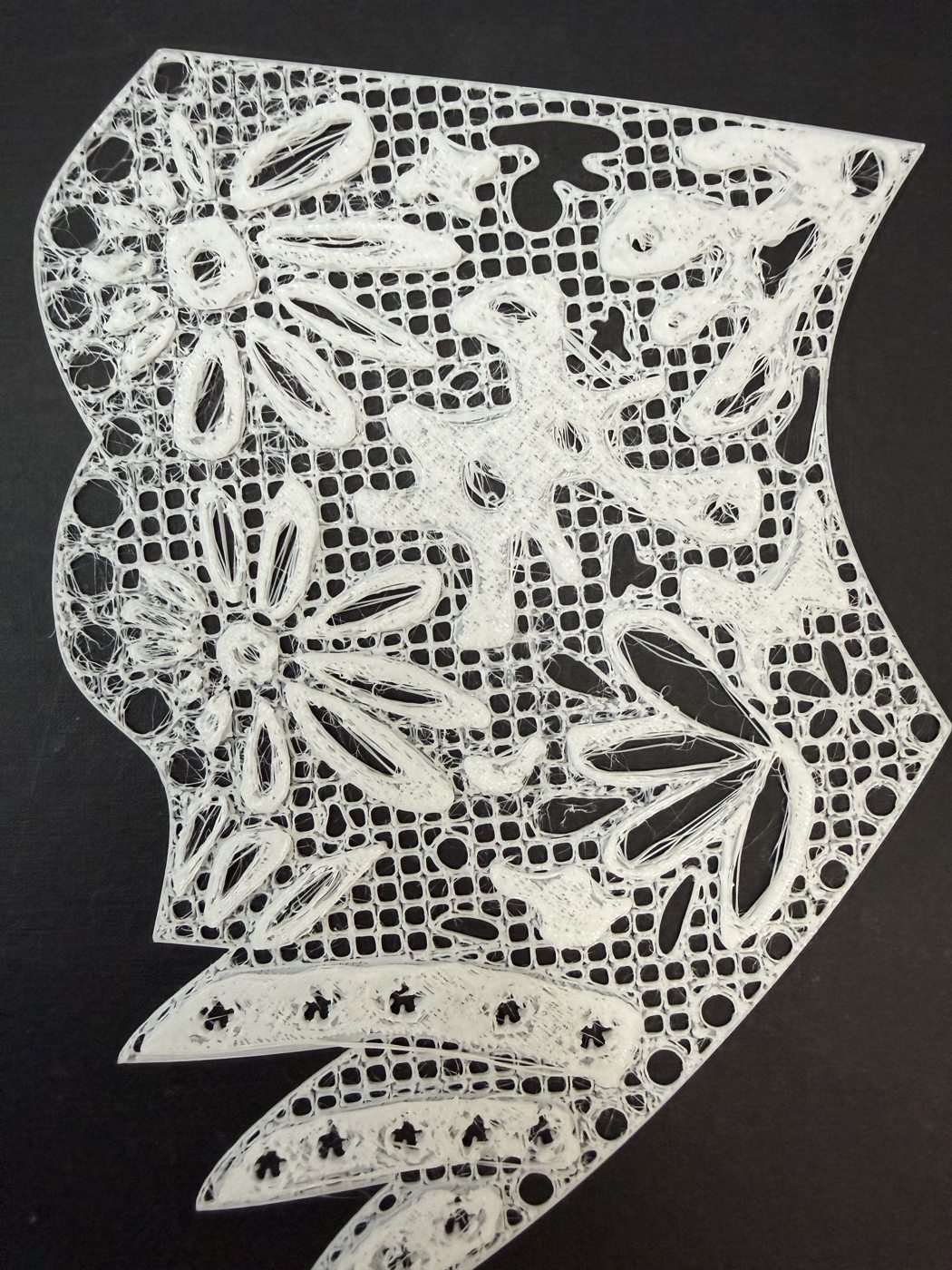
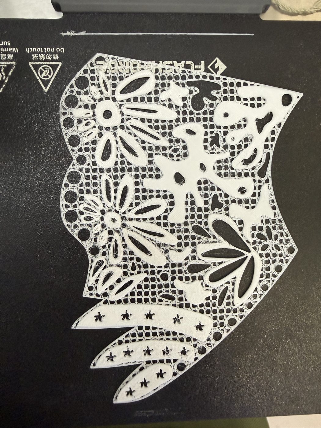
Printing difficulty: repeating F1
I had to print F1 again. During one attempt, the spool became stuck and interrupted the filament feed, so some layers were not deposited properly. I found that the filament was tightly wound on the spool. When repeating the print, I paid close attention to keeping the filament entering the printer free to move so that it would not get caught again.
My evaluation
I am very happy with the final result. This experience also showed me that I needed to pay attention to the TPU feed during printing. For F1, keeping the filament free to move was an important part of completing the print.
6. What I learned
Grasshopper and Rhino felt quite complex, but I learned a lot about how they work. I began to understand the commands, how to enter numerical values, and how the result changes as I connect different elements.
I do not yet feel able to repeat the whole process on my own. However, I think that continuing to practise with AI guidance and mentorship can help me gradually learn to work more independently. Mar helped me throughout the process, and I learned to use Rhino’s freehand drawing tools with her.
7. Fabrication files and references
Design and fabrication files
The files use the final names T1, T2, F1, F2 and HOMBROS. I developed the parametric outline of T1 in Grasshopper, drew the decorative curves in Rhino, and used AI assistance to prepare and correct the final printable geometry. The STL files contain the final printable models. G-code files preserve the machine instructions prepared for this printer profile.
The G-code is specific to the recorded printer profile and setup. A different machine requires a new slicing setup.
Rhino models
- Rhino-F1.zip — 3.61 MB
- Rhino-F2.zip — 3.61 MB
- Rhino-HOMBROS.zip — 1.22 MB
- Rhino-T1.zip — 6.07 MB
- Rhino-T2.zip — 3.21 MB
STL models
- STL-F1.zip — 3.26 MB
- STL-F2.zip — 3.28 MB
- STL-HOMBROS.zip — 1.34 MB
- STL-T1.zip — 2.76 MB
- STL-T2.zip — 2.81 MB
G-code files
- GCODE-F1_TPU_2h8m.zip — 2.62 MB
- GCODE-F2_TPU_2h8m.zip — 2.64 MB
- GCODE-HOMBROS_TPU_37m48s.zip — 0.56 MB
- GCODE-T1_TPU_2h37m.zip — 2.97 MB
- GCODE-T2_TPU_2h37m.zip — 2.98 MB
References and credits
- Course: Fabricademy global Computational Couture masterclass — the 2D-to-3D approach followed in this exercise. Session link to be added.
- Student work: Lorena Méndez and Pamela Rivas — graduation projects from the Sustainable Fashion and Textile Design undergraduate program at IBERO CDMX.
- Professional design: Sophy Wong’s website, source of my selected images. Individual project and photographic credits still to be completed.
- Design book: Laird Borrelli-Persson, Marimekko: The Art of Printmaking, pp. 37, 69, 124 and 246. My physical copy was the source of these references.
- Lace research: Pinterest reference, a discovery source whose original image credit remains to be traced; Sara Sáez, ’t Apostelientje: El templo del Encaje de Brujas, Folkmania, a cultural article. Exact correspondence with the individual reference images still to be confirmed.
- Personal material reference: my own lace collar purchased in Belgium. This reference is separate from the images found online.
- Material data: the photographed PolyFlex TPU90 packaging; slicing settings extracted from my saved OrcaSlicer G-code files.
8. My Work, Learning and AI Support
I developed the collar concept through my fashion and textile references, hand-drawn sketches and patterns. I made a paper prototype on a mannequin to explore the shape, proportions and arrangement of the pieces. Following the approach introduced in the global masterclass, I worked from 2D patterns towards 3D printed pieces intended for traditional assembly.
In Grasshopper, I worked step by step on the parametric outline of T1. I learned how to connect components, enter numerical values and adjust parameters to change the shape. This introduced me to a different way of approaching patternmaking, where dimensions and relationships can be adjusted through connected elements.
In Rhino, I drew decorative shapes based on my original designs. For F1, I placed my drawing as a reference and traced the cut-outs and reliefs in separate layers. I also drew the decorative perforations for the shoulders. Throughout the process, I made decisions about shapes, thicknesses, borders, connections and which details to simplify.
I worked with the files in Cura and OrcaSlicer, prepared them for printing and participated in fabrication. Mar, my mentor, supported my learning throughout the process and helped me use Rhino’s freehand drawing tools.
I used ChatGPT as a technical guide to explain tools, help diagnose problems and assist with preparing and correcting digital geometry and files based on my drawings and decisions. For documentation, ChatGPT/Codex helped organise, translate and edit my material, compile saved settings and prepare images, including a background edit of my lace photograph. I selected what to retain and reviewed the content; the design decisions and reflections are my own.