5. E-TEXTILES AND WEREABLES I#
This was my first encounter with electronics, at first to understand the language, codes and understand this new world was not easy, but once you manage to light your first LED, that micro moment of happiness encourages you to continue researching and exploring this new e-way. In this documentation I will include my annotations, diagrams and all the links that were useful for me to understand and experiment with e-textiles.
Electronics / basic concepts#
The electronics have their own language and symbols with which we must begin to familiarize ourselves:
- V = Voltage
- I = Current
- R = Resistance
Electric current is the movement or passage of electricity along the electric circuit from the electricity generator to the device where it will be used, which we will call the receiver, through the conductors. In order for the electric current to originate, it is necessary that the generator produces an electromotive force that creates a potential difference between the terminals or poles of the generator:
- This potential difference is called voltage or voltage and is measured in VOLTS (V).
- The amount of electricity that passes through a conductor in a second is called current intensity and is measured in AMPS (A).
- The difficulty offered by the driver to the passage of an electric current is called electrical resistance and is measured in OHMIOS (Ω).
Electrical circuit: it is a set of elements connected together by which an electric current can circulate.
The elements that form a basic electrical circuit are:
- Generator: produce and maintain the electrical current through the circuit. They are the source of energy.
- Conductors: is where the electric current moves from one element to another circuit.
- Receptors: are the elements that transform the electrical energy that reaches them in another type of energy. For example, light bulbs transform electrical energy into light or light, radiators into heat, motors into motion, etc.
- Elements of command or control: they allow to direct or cut at will the passage of the electric current inside the circuit. We have switches, push buttons, switches, etc.
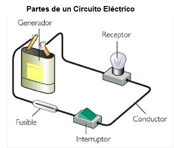
To simplify the drawing of electrical circuits, diagrams with symbols are used. The symbols represent the elements of the circuit in a simplified and easy to draw way.
Symbols of the most common elements used in electrical circuits.
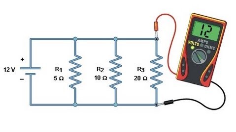
Multimeter, also called multimeter or tester, is a portable electric instrument for directly measuring active electrical quantities, such as currents and potentials (voltages), or passive, such as resistance, capacitance and others.
Sensors#
A sensor is an electronic device that is constantly measuring a physical variable (temperature, distance, etc.) and transforms it into an electrical signal.
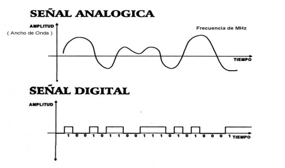
- Digital Sensors: are those that in front of a stimulus can change state either from zero to one or from one to zero (speaking in terms of digital logic) in this case there are no intermediate states and the voltage values obtained are only two, 5V and 0V (or very close values).
- Analog sensors: are those that can detect small voltage differences depending on the changes suffered by the measured physical variables. The resolution of the analog inputs of the Build & Code One board is 10 bits, this means that you can detect up to 210 = 1024 intermediate values between 0 and 5V, and they are proportional to the effects that are being measured.
Digital Sensor#
Once the theory was understood, it was time to put it into practice, I decided for my first sample to make a machine embroidered circuit with a cloth button sensor that allows the turning on and off of 3 LEDs. The first step was to turn on the first LED and analyze which was the best option in terms of diagram, operation of the circuit and textile materials to be used:
Multiple LEDs in parallel
LEDs connected in parallel use a cable to connect all the positive electrodes of the LEDs used to the positive cable of the power supply and another cable to connect all the negative electrodes of the LEDs used for the negative cable of the power supply. Wiring things in parallel has some distinct advantages over wiring things in series. If you wire a bunch of LEDs in parallel instead of dividing the power supplied between them, they all share it. Then, a 12V battery connected to four 3V LEDs in series would distribute 3V to each of the LEDs. But that same 12V battery connected to four 3V LEDs in parallel would deliver 12V to each LED, enough to burn the LEDs safely!
The wiring of LEDs in parallel allows many LEDs to share only one low-voltage power supply. We could take those same four 3V LEDs and connect them in parallel to a smaller power supply, for example, two AA batteries that emit a total of 3V and each of the LEDs would get the 3V they need. In summary, the serial wiring divides the total power supply between the LEDs. Wiring them in parallel means that each LED will receive the total voltage that the power source is emitting. Some warnings … parallel wiring drains your power supply faster than serial wiring because they end up drawing more current from the power source. It also works only if all the LEDs you are using have exactly the same power specifications. DO NOT mix or match different types / colors of LEDs when wiring in parallel. Taking into account the operation of a circuit of LEDs in parallel, I decided to use 3 equal, of White color, these are the characteristics:
WHITE LED:
- 20 mA
- 3.0 - 3.2 V
- 12000 - 14000 mcd
Calculate the Resistance / Formula:
R = (V1 - V2) / I
- V1: Voltage of the power supply
- V2: LED voltage
- I: LED current (usually 20mA = .02A)
R for my circuit:
R = (9V-3.0) / (0.2A x 3)
R = 100 Ω
You can also use
Fabric Circuit Construction, Step by step:
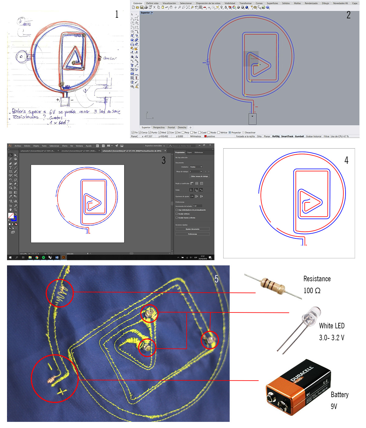
- 1 I drew the design of my circuit on paper, identifying its components.
- 2 I digitally drew my 2D circuit in Rhino, including the actual measurements and chords to the workspace of the embroidery machine (240 x 200 mm).
- 3 I passed my drawing to Illustrator to give thickness to the drawing lines and export it in PNG, SVG format and see which one worked best.
- 4 I opened my file in the “Brird Embroidery” program and made the necessary adjustments, transformed the continuous lines and generated a simulation of the embroidery to corroborate the correct operation.
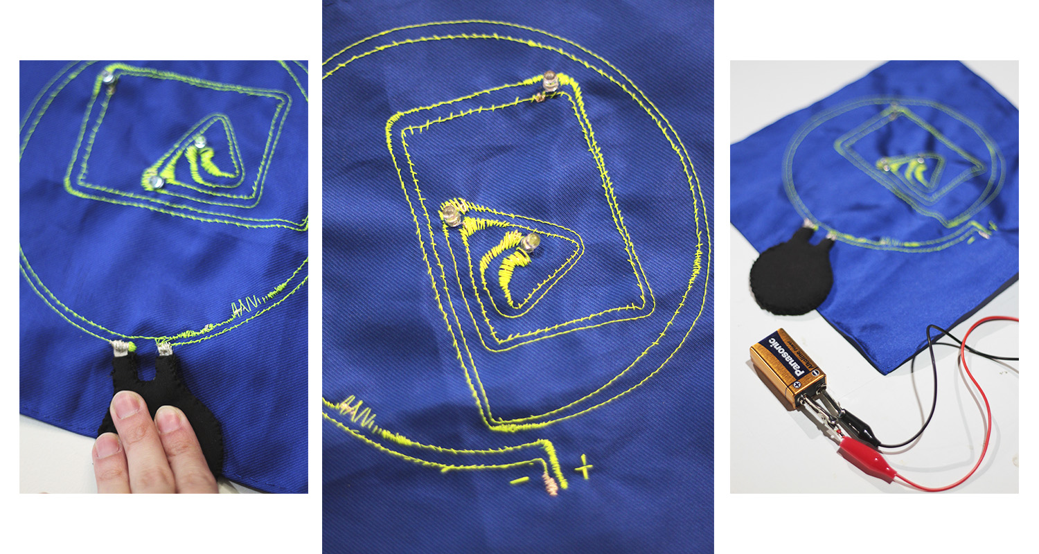
- 5 It is important to place the fabric cut-out on the frame of the machine so that it is tight enough to prevent it from buckling and generating deformations in the design. Make sure that the conductive thread (which is underneath) and the sewing thread that remains in view (in this case lime green) are correctly threaded. Once the machine finished the embroidery, I had to make some adjustments by hand, such as cutting leftover threads, reinforcing some sections. The last step was to place the LEDs and the sensor (cloth button) and connect them to the circuit with conductive wire, hand stitches.
Circuit Sample + Finished digital sensor
Analog Sensor#
As I mentioned earlier, an analogue sensor within a circuit allows reading a range of data and information (INPUT) and consequently generating an effect (OUTPUT). For this it is necessary to use software and hardware, we discover and experiment with Arduino in principle.
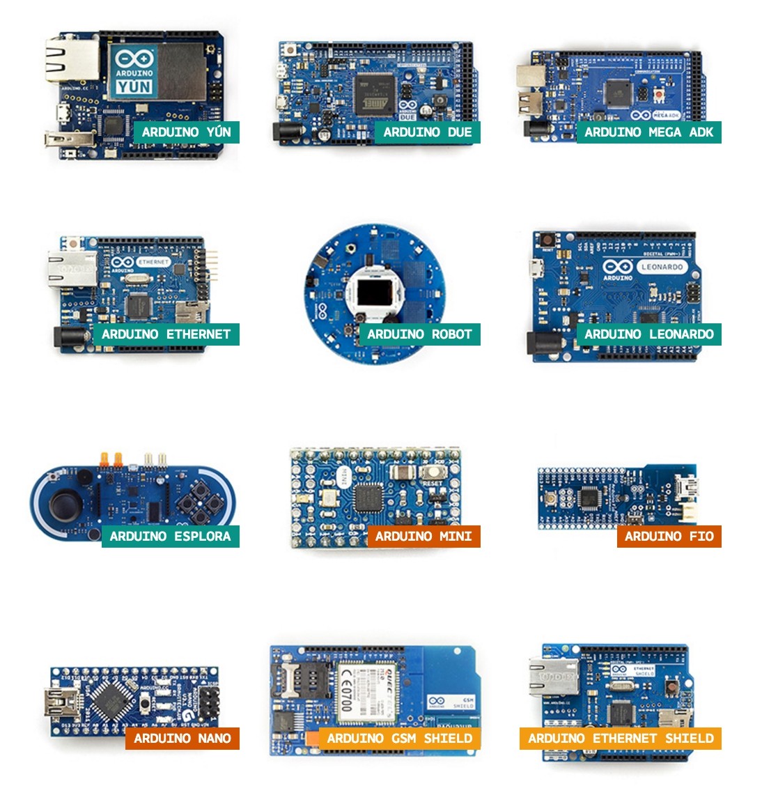
Arduino
Arduino is a platform for the creation of open source electronics, which is based on hardware and free software, flexible and easy to use for creators and developers. This platform allows to create different types of microcomputers of a single plate to which the community of creators can give them different types of use. Arduino, has what is called an input interface, which is a connection in which we can connect different types of peripherals on the board. The information of these peripherals that you connect will be transferred to the microcontroller, which will process the data that arrives through them. It also has an exit interface, which is responsible for taking the information that has been processed on the Arduino to other peripherals. These peripherals can be screens or speakers in which to reproduce the processed data, but they can also be other boards or controllers.
FLORA electronic platform
FLORA is the Adafruit Arduino compatible microcontroller, designed to empower incredible clothing devices projects. FLORA is designed around the ATMEGA32U4 microcontroller with V 3.3 logic and has a built-in USB and USB HID which allows it to function as a mouse or keyboard to connect directly to the equipment. It is easily programmed via USB using the Arduino IDE.
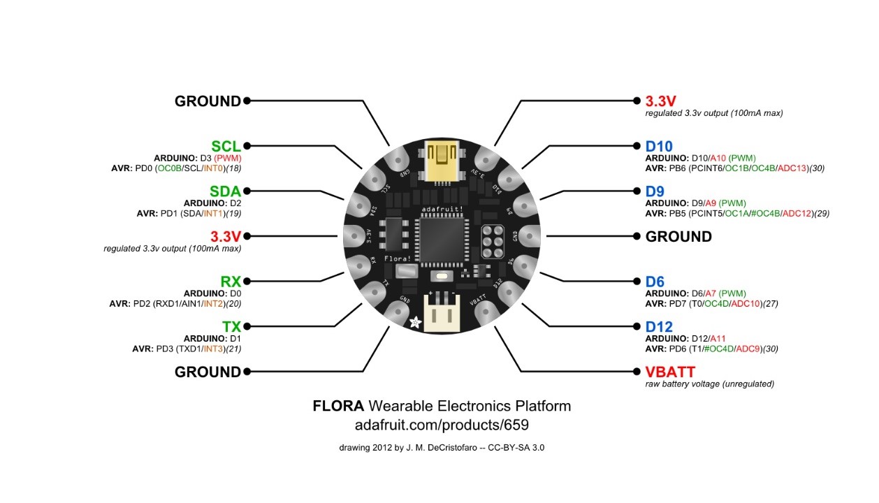
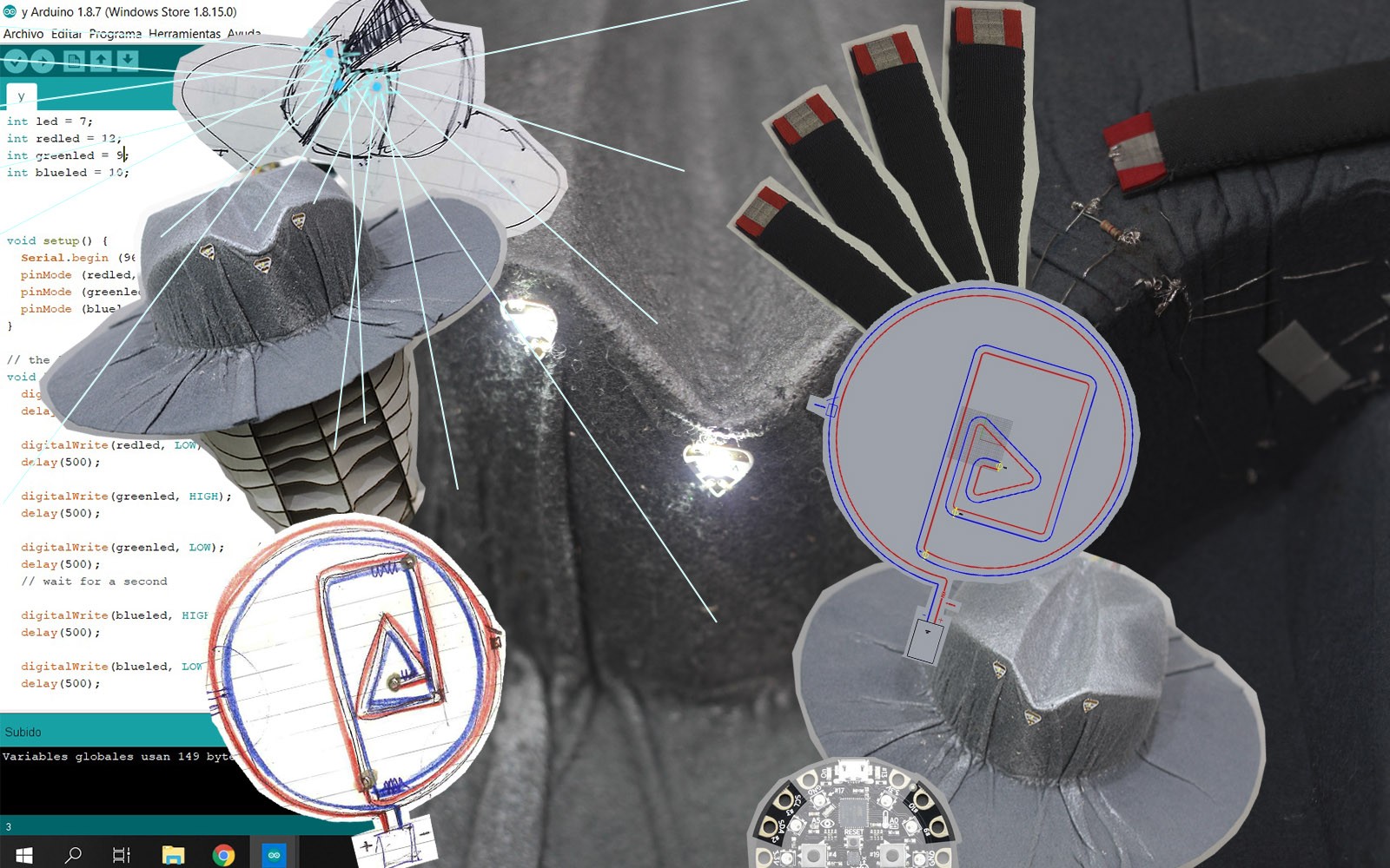
This was my graphic that helped me understand how this type of microcontroller works.
In the beginning we explored the basic codes of the library to understand the language and functioning of Arduino, in a simple circuit with an LED, here are some examples:
void setup() {
  // initialize digital pin LED_BUILTIN as an output.
  pinMode(LED_BUILTIN, OUTPUT);
}

// the loop function runs over and over again forever
void loop() {
  digitalWrite(LED_BUILTIN, HIGH);   // turn the LED on (HIGH is the voltage level)
  delay(1000);                       // wait for a second
  digitalWrite(LED_BUILTIN, LOW);    // turn the LED off by making the voltage LOW
  delay(1000);                       // wait for a second
}
int led = 9;           // the PWM pin the LED is attached to
int brightness = 0;    // how bright the LED is
int fadeAmount = 5;    // how many points to fade the LED by

// the setup routine runs once when you press reset:
void setup() {
  // declare pin 9 to be an output:
  pinMode(led, OUTPUT);
}

// the loop routine runs over and over again forever:
void loop() {
  // set the brightness of pin 9:
  analogWrite(led, brightness);

  // change the brightness for next time through the loop:
  brightness = brightness + fadeAmount;

  // reverse the direction of the fading at the ends of the fade:
  if (brightness <= 0 || brightness >= 255) {
    fadeAmount = -fadeAmount;
  }
  // wait for 30 milliseconds to see the dimming effect
  delay(30);
}
Bend Sensor#
For my Circuit + analog sensor sample, I decided to build a Bend Censor that could be placed on the wing of a felt hat (which I had previously molded as part of a material scan) to achieve the ignition of 3 micro-LEDs positioned in the helmet of the same.
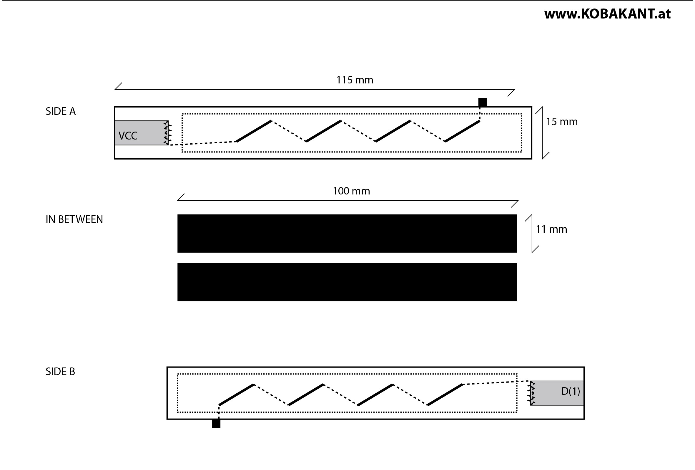
Neoprene folding sensor construction step by step:
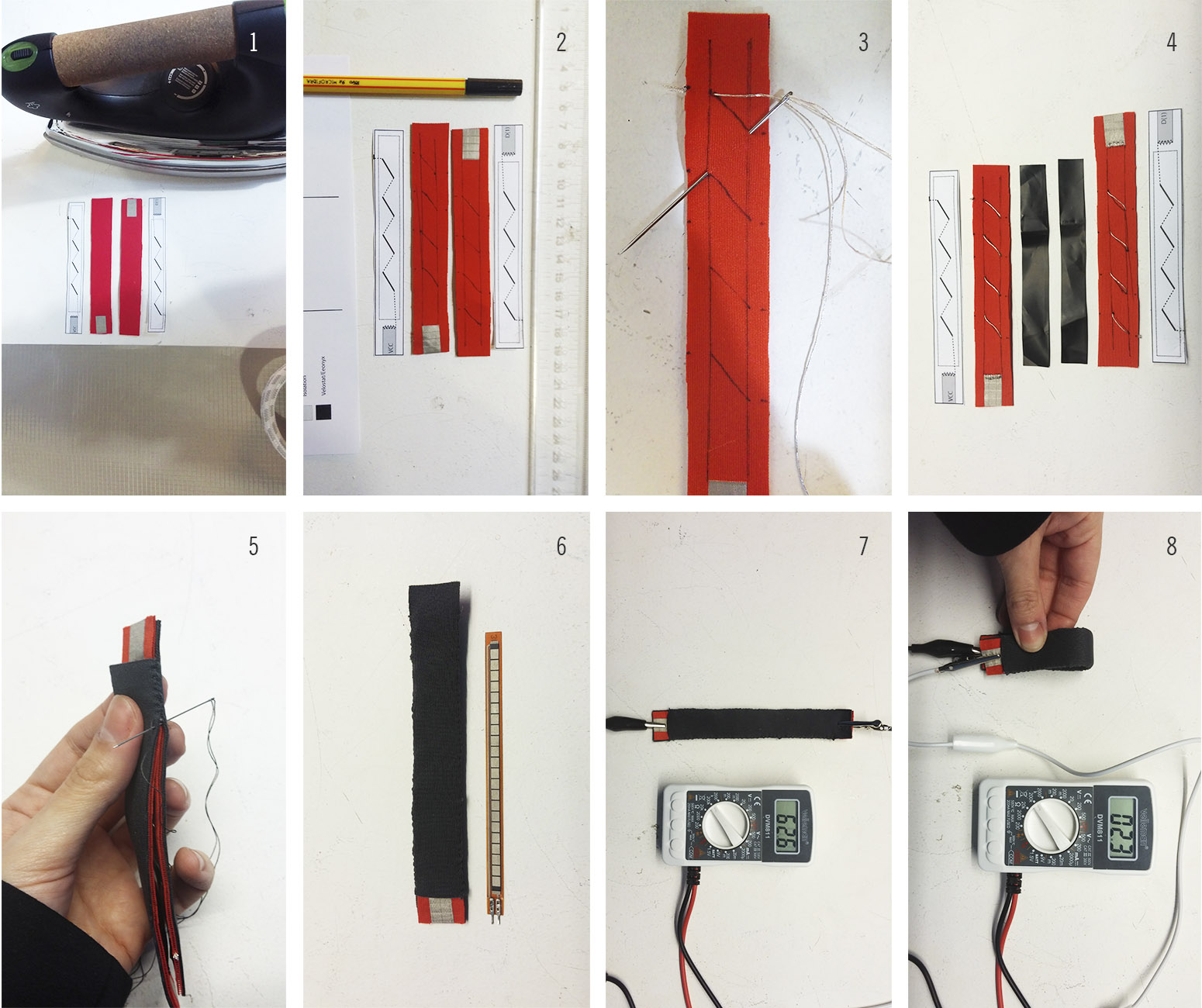
- 1 I downloaded and printed the scale template on the Kobakant page, which made the task much easier. I cut the segments in neoprene and with the heat of the plate I adhered the thermoadhesive completions of conductive fabric.
- 2 I drew the guide lines and segments of the route to be embroidered with the conductive thread, since it is important that they be equal and symmetrical with each other.
- 3 I marked the conductive thread path in the 2 pieces, connecting them in their final section with the conductive fabric.
- 4 I cut the Velostat segments that will then be inserted inside the sensor, in the form of a sandwich. Achieving thus having all the components ready of it.
- 5 I placed both sides facing one another, containing the velostat segments in the middle. Then with common sewing thread I made a seam by hand to close it.
- 6 Image of the finished sensor, comparison in terms of dimensions with a commercial folding sensor.
- 7/8 Then, with a multimeter, I measured its resistance in the extreme and intermediate positions, in order to obtain the values applicable later to the Arduino code. Once the sensor was finished, I had to enter the values and create the code in Arduino to check the operation of it with a led.
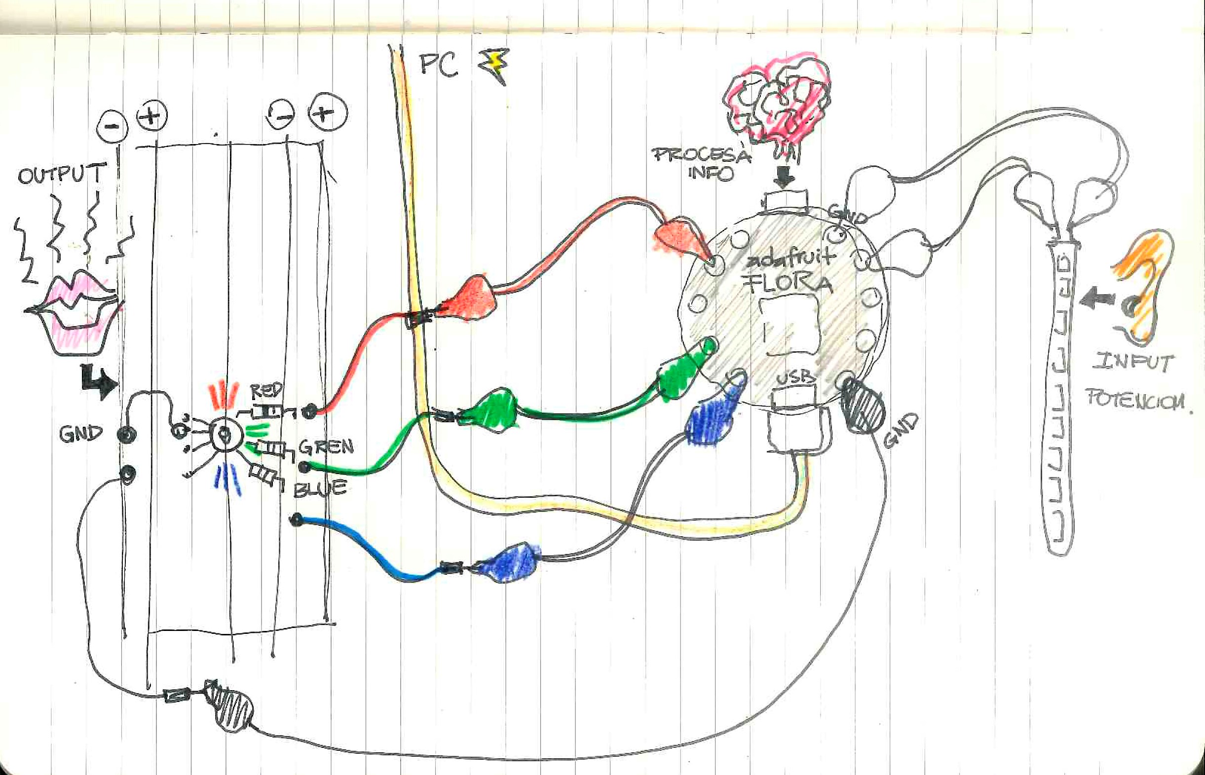
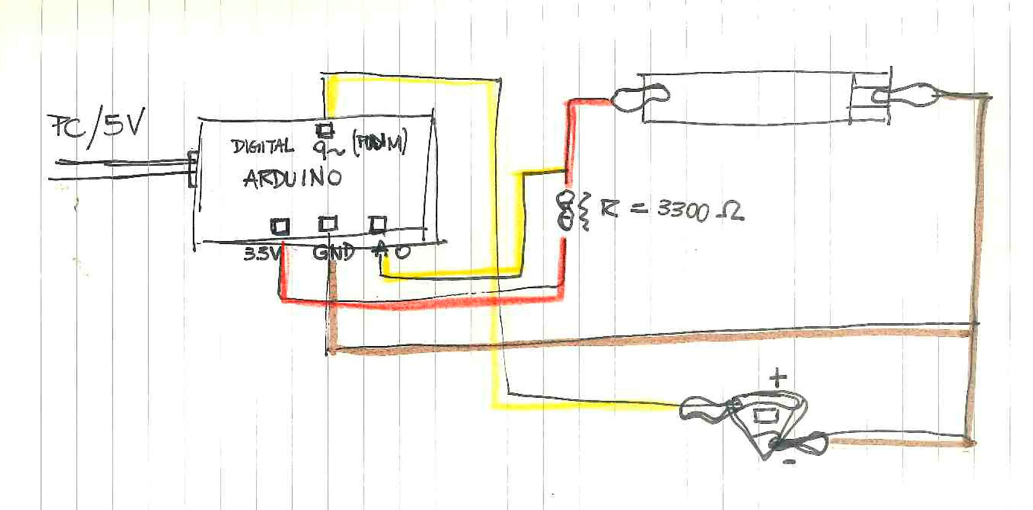
Graph of the circuit and its components
Arduino Code / Bend Sensor + Led
void setup() {
  // initialize serial communication at 9600 bits per second:
  pinMode(9,OUTPUT);
  Serial.begin(9600);
}

// the loop routine runs over and over again forever:
void loop() {
  // read the input on analog pin 0:
  int sensorValue = analogRead(A0);
  Serial.println(sensorValue);
  // print out the value you read:
  sensorValue = constrain(sensorValue,300,600);
  int ledOut = map(sensorValue,300,600,255,0);
  analogWrite(9,ledOut);

  delay(1);        // delay in between reads for stability
}
e-Hat#
Step by step of the application of the components and construction of the circuit on the hat:
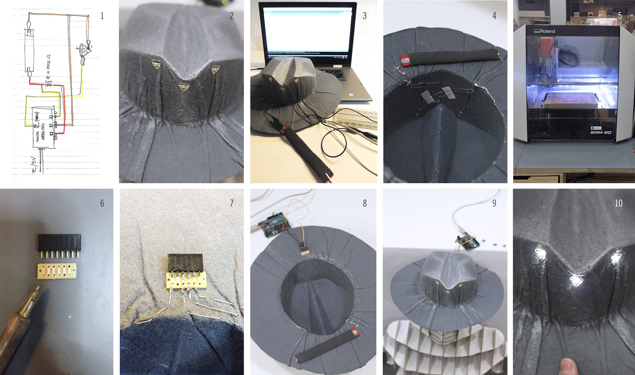
- 1 With the help of the previously plotted circuit, I located the components of the circuit on the wereable hat.
- 2 I used 3 self-adhesive SMD micro LEDs ideal for textiles, which already have a built-in resistance.
- 3 With conductive thread and needle embroidered inside the helmet of the hat the parallel circuit for the 3 LEDs. Then, I checked its operation with the sensor and the Arduino code connecting the sensor and actuators with crocodiles.
- 4 I placed the sensor on the wing of the hat and connected it to the rest of the circuit with conductive wire, for its best operation I included an R = 3300 Ω
- 5 In order to connect the components of the circuit to the Arduino board in a more neat way, in the Roland milling machine I cut a basic copper PCB board.
- 6 Then I had to solder the female connections to the board, in order to connect the jumpers.
- 7 Sew the board and connections on the back of the hat, and finish joining the circuit with conductive wire.
- 8 I jumpered the circuit to the Arduino board.
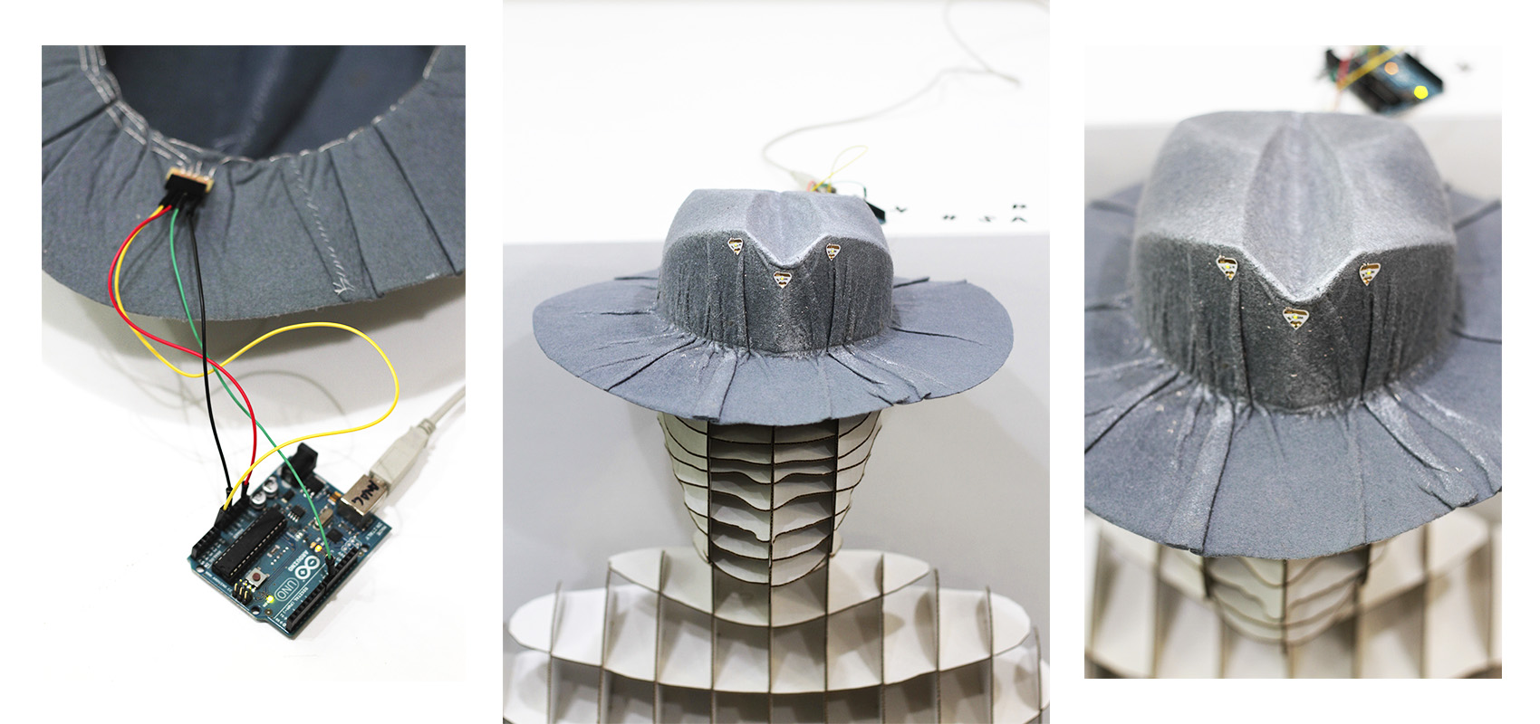
- 9 I put the hat on my mannequin to finally see if it worked, as I had thought.
- 10 Yes! The lights come on perfectly when the hat brim is curved.
Final Result#
Useful links#
To see this sensor in action have a look at the following video. The dancer has fabric bend sensors: