10. E-Textiles and Wearables II
This week was focussed on some more advancements in textile and wearables using sensors and actuators to make smart things.
Inspiration
| Smart Textiles, Be Smart - Inspiration Video |
|---|
| Smart Textiles, Be Smart - Inspiration Video |
|---|
Assignment
The assignment of this week was to learn how to design and make program for the bracellet and integrate it with Adafruit Circuit Playground Express.
| Assignment |
|---|
 |
Introduction
Sensor
Sensors used by computers must give data in a digital form. The Arduino reads sensor data as voltage which is handled by the code as numbers. This means that the brightness of the reflected light will show up as numbers for the student engineers to process and display. Remember that when sensors read data, this counts as input data for the microcontroller. Students can then output this data in some useful way.
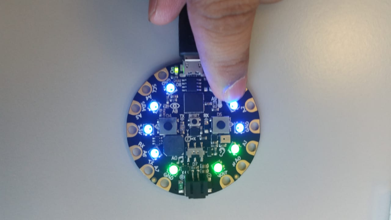
Adafruit Circuit Playground Express
The Adafruit Circuit Playground Express comes equipped with an analog light sensor, but it can be used for much more than just sensing light or darkness! The light sensor has a similar spectral response to the human eye. Its connected to analog pin A8 and will return a value between 0 and 1023. A normal indoor light level reading is about 300, with higher numbers being brighter.
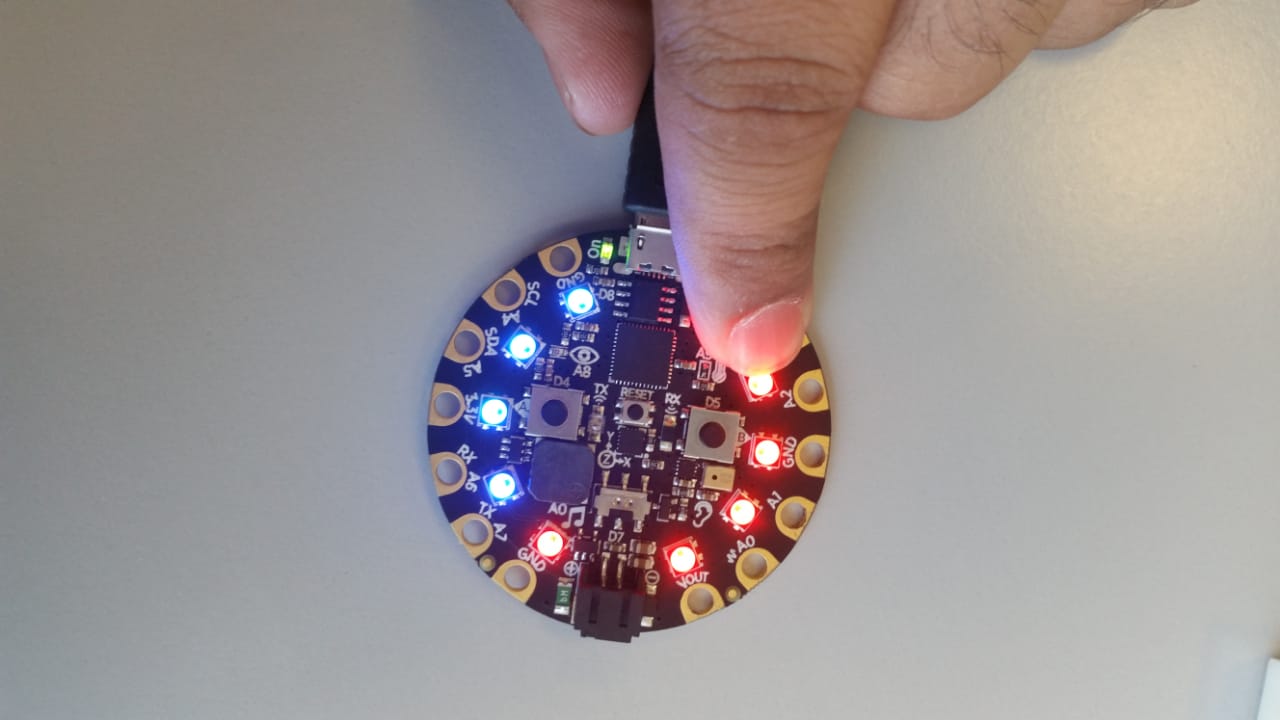
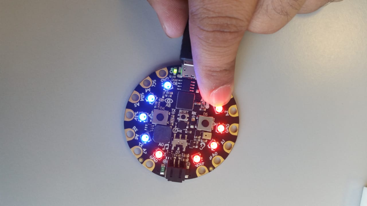
With a light sensor we can obviously read ambient light, but we could also use it to sense color or to measure your heartbeat. For this week, I will use the light sensor to measure a heart beat.
| Working Principle of Adafruit For Heart Beat Monitor |
|---|
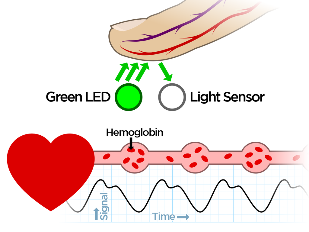 |
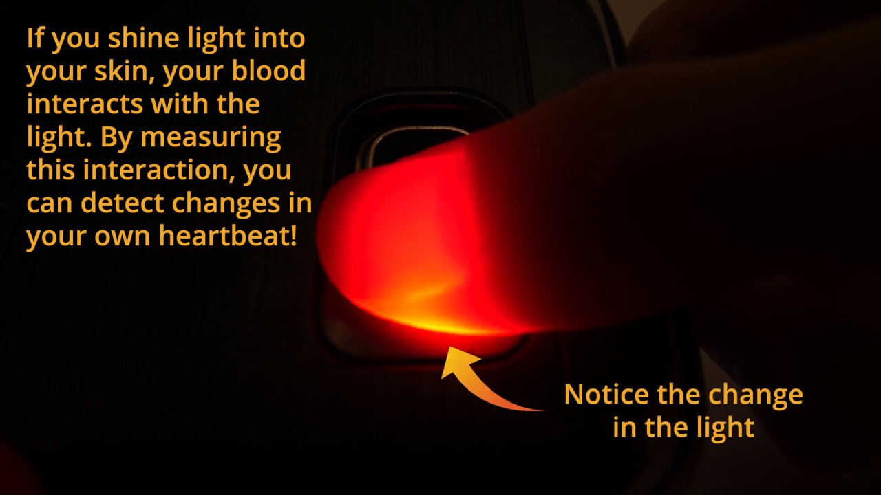
The detection of your pulse via your finger via light is called Photoplethysmogram.
Light shines onto the finger and a light detector measures the light that returns. We use green light, which is absorbed by red blood. The redder the blood, the more green light is absorbed. The blood pumping through one's finger will change the absorption of the light. Not by much but enough to measure. These variations can be plotted over time to see the changes.
The readings will also vary by ones breathing and if the finger shifts while taking readings. So make sure you keep your finger still, to avoid unintended light changes.
| Assignment |
|---|
 |
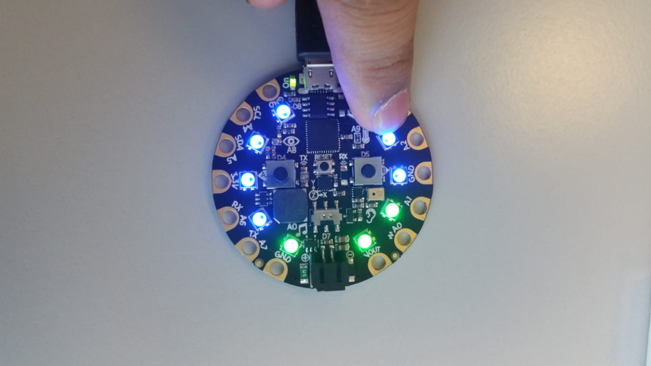
Heart Rate, Noise and Temperature Monitor
I used circuit playgroud to monitor heart rate, noise and storm and temerature monitor. It will be used in the application of smart cart for monitoring babied health.
| Heart Beat Monitor | Noise Monitor | Temperature on Serial Monitor |
|---|---|---|
 |
 |
 |
 |
 |
 |
 |
 |
 |
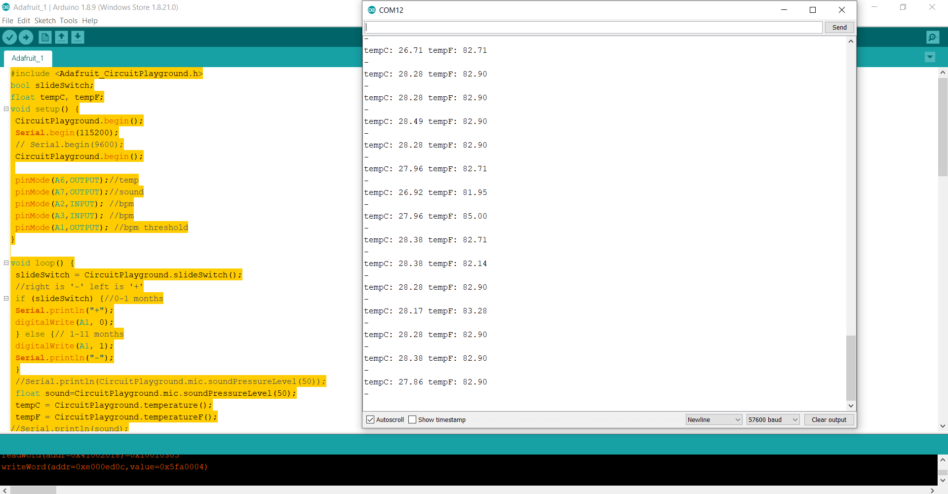
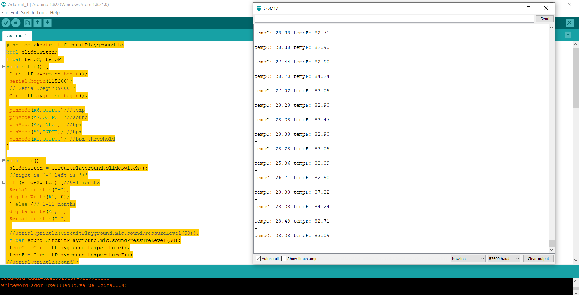
Code Example
Use the three backticks to separate code.
#include <Adafruit_CircuitPlayground.h>
bool slideSwitch;
float tempC, tempF;
void setup() {
CircuitPlayground.begin();
Serial.begin(115200);
// Serial.begin(9600);
CircuitPlayground.begin();
pinMode(A6,OUTPUT);//temp
pinMode(A7,OUTPUT);//sound
pinMode(A2,INPUT); //bpm
pinMode(A3,INPUT); //bpm
pinMode(A1,OUTPUT); //bpm threshold
}
void loop() {
slideSwitch = CircuitPlayground.slideSwitch();
//right is '-' left is '+'
if (slideSwitch) {//0-1 months
Serial.println("+");
digitalWrite(A1, 0);
} else {// 1-11 months
digitalWrite(A1, 1);
Serial.println("-");
}
//Serial.println(CircuitPlayground.mic.soundPressureLevel(50));
float sound=CircuitPlayground.mic.soundPressureLevel(50);
tempC = CircuitPlayground.temperature();
tempF = CircuitPlayground.temperatureF();
//Serial.println(sound);
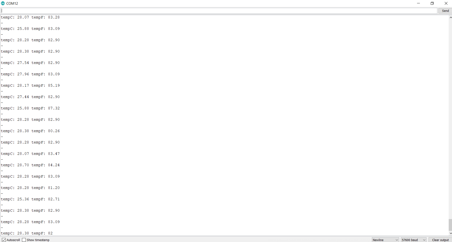
Serial.print("tempC: ");
Serial.print(tempC);
Serial.print(" tempF: ");
Serial.println(tempF);
//*************************************************************Temperature
// delay(1000);
if (tempF >= 85); (tempF <= 95);{
CircuitPlayground.setPixelColor(0, 0, 255, 0);
CircuitPlayground.setPixelColor(1, 0, 255, 0);
CircuitPlayground.setPixelColor(2, 0, 255, 0);
CircuitPlayground.setPixelColor(3, 0, 255, 0);
//digitalWrite(A5,0);
}
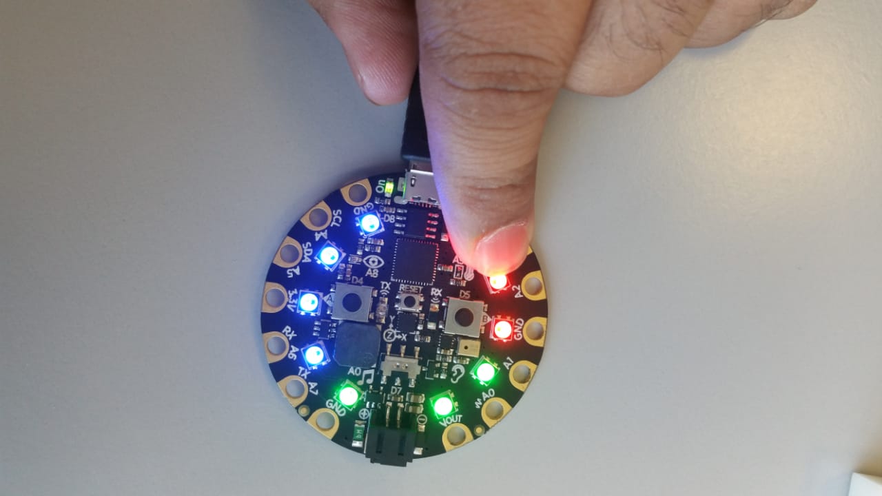
if (tempF >= 95){
CircuitPlayground.setPixelColor(0, 255, 0, 0);
CircuitPlayground.setPixelColor(1, 255, 0, 0);
CircuitPlayground.setPixelColor(2, 255, 0, 0);
CircuitPlayground.setPixelColor(3, 255, 0, 0);
digitalWrite(A6,1);
}
if (tempF < 85){
CircuitPlayground.setPixelColor(0, 0, 0, 255);
CircuitPlayground.setPixelColor(1, 0, 0, 255);
CircuitPlayground.setPixelColor(2, 0, 0, 255);
CircuitPlayground.setPixelColor(3, 0, 0, 255);
digitalWrite(A6,0);
}
//*************************************************************SOUND
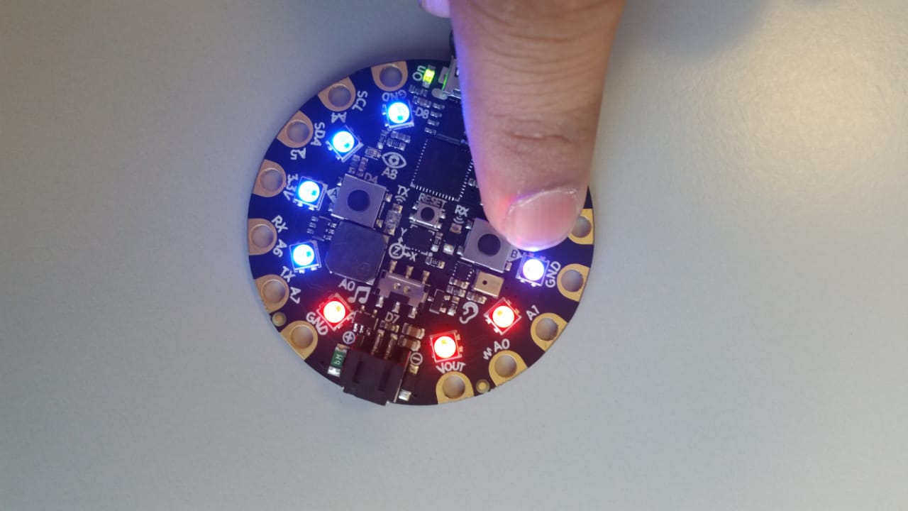
if (sound>=80){
digitalWrite(A7,1);
CircuitPlayground.setPixelColor(4, 255, 0, 0);
CircuitPlayground.setPixelColor(5, 255, 0, 0);
CircuitPlayground.setPixelColor(6, 255, 0, 0);
}
else if (sound<80){
digitalWrite(A7,0);
CircuitPlayground.setPixelColor(4, 0, 255, 0);
CircuitPlayground.setPixelColor(5, 0, 255, 0);
CircuitPlayground.setPixelColor(6, 0, 255, 0);
digitalWrite(A3,2);
}
//*************************************************************BPM
float BPM=digitalRead(A2);
float BPM2 = digitalRead(A3);
if (BPM==1) { //high
CircuitPlayground.setPixelColor(7, 255, 0, 0);
CircuitPlayground.setPixelColor(8, 255, 0, 0);
CircuitPlayground.setPixelColor(9, 255, 0, 0);
}
else if (BPM==0) { //low
CircuitPlayground.setPixelColor(7, 0, 0, 255);
CircuitPlayground.setPixelColor(8, 0, 0, 255);
CircuitPlayground.setPixelColor(9, 0, 0, 255);
}
else if(BPM ==2) { //normal
CircuitPlayground.setPixelColor(7, 0, 255, 0);
CircuitPlayground.setPixelColor(8, 0, 255, 0);
CircuitPlayground.setPixelColor(9, 0, 255, 0);
}
}
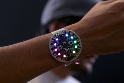
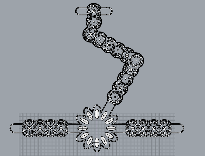
After getting seccesfull result i made a design in Rhinoceros for bracelet to fix adafruit circuit playground on it and also to make it wearable.
| Bracelet Design | Bracelet Design in Rhinoceros |
|---|---|
 |
 |
|
|
Useful links
| Assignment |
|---|
|
| Assignment |
|---|
|
Assignment No. 1
The assignment of the week was to
a) - Create a swatch using an ATtiny with one input and one output, using hard-soft connection solutions and battery
b) - Create 2 actuator swatches. Test them with the Arduino or ATtiny
ATtiny
ATtiny (also known as TinyAVR) are a subfamily of the popular 8-bit AVR microcontrollers, which typically has fewer features, fewer I/O pins, and less memory than other AVR series chips.
ATtiny 85
ATtiny85 is an 8-bit AVR microcontroller that comes with 8-pin interface and mainly used in automation and Arduino projects.
The CPU is based on RISC architecture and is mainly called low power controller that stands fit for the real-time applications that can operate on minimum power.
The program memory is 8KB while both EEPROM and RAM contain a memory space of around 512 bytes. These memory spaces are very useful for storing the number of instruction in the form of code.
This module comes with only one port called Port B that is a bi-directional port and contains 6 I/O pins with internal pull-up resistors. The output buffers on PORTB are designed with symmetrical drive characteristics that come with both high sink and source capability. It is important to note that, Port B pins are externally pulled low and tri-stated that will source current if the pull-up resistors are activated.
External and internal interrupts are available on the board, while 32 general purpose registers are included in the device that are mainly called data holding spaces.
Two 8-bit timers are added in the device where one timer comes with compare modes and can be used both ways i.e. timer as well as a counter while other is high-speed timer/counter.
This module comes with software select power saving modes that are very helpful for the applications that operate with minimum power.
| ATtiny 85 |
|---|
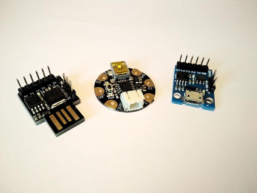 |
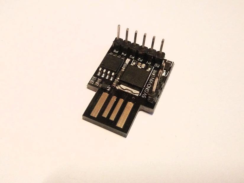
ATtiny 85 Development Board
The ATtiny85 is a microcontroller in a similar vein to the Arduino, but with much less IO pins, smaller memory and a smaller form factor. In fact, when we talk about the ATtiny85 we refer to the IC itself rather than the board. The ATtiny85 can be used as a bare chip on a breadboard, as long as you can supply the correct power for the device.
But most commonly the ATtiny85 is supplied with a USB interface, either a full USB port such as the DigiStump Digispark or micro USB via a cloned board commonly found on Aliexpress, Amazon etc.
Despite the small package, the ATtiny85 comes with a remarkable number of ways in which we can interface. At the most basic level, we have 5V logic digital I/O pins, three of which can also be used as analog pins for use with components such as the TMP36 sensor. Four of the available pins can also be used with Pulse Width Modulation (PWM). Also available is I2C and SPI for use with other types of sensors and devices.
| ATtiny 85 Development Board |
|---|
 |
Software Setup
Open the Arduino application and click on File >> Preferences and past the following into the Additional Boards Managers URLs: dialog.
| ATtiny 85 Development Board Setup in IDE |
|---|
 |
Next, go to Tools >> Board >> Boards Manager and from the drop-down menu select “Contributed”.
| Board Manager Setup in IDE |
|---|
 |