9. Textile as scaffold
COMPOSITE We consider a composite to be a material consisting of two or more distinct phases, bonded together. Composite contain both reinforcements (increase the mechanical properties of a composite, it can be fibers, fabric particles...)and matrix materials. The matrix material is the homogeneous and monolithic material in which a reinforcement system of a composite is embedded and is completely continuous. The main purpose of the Matrix is to bind the reinforcements together.
Fabric leftovers composite process (+ epoxy resin + fast hardener);
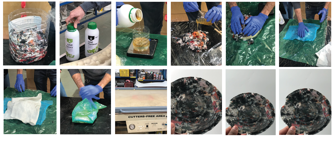
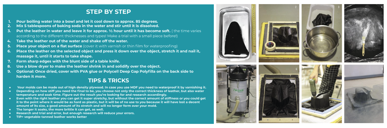
Leather molding explanation and process;
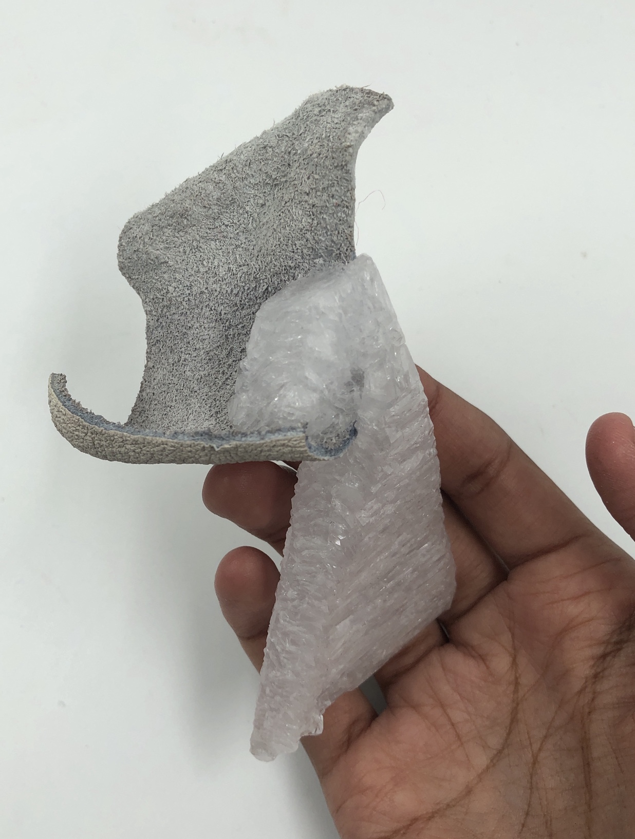
CRISTALIZATION you can manipulate the growth of the crystal dependiendo de la temperatura
Alumn ; Aluminium-based alums have a number of common chemical properties. They are soluble in water, have a sweetish taste, react acid to litmus, and crystallize in regular octahedra. In alums each metal ion is surrounded by six water molecules. When heated, they liquefy, and if the heating is continued, the water of crystallization is driven off, the salt froths and swells, and at last an amorphous powder remains
Tools weight, cooking pot, spoon, paper filters, cooking stove, glass jars, fabrics.
Process * Heat the water without reaching boiling tempreture * measured my alum and add (200g alumn per 1l water). Stirr constantly until all is disolved * Turn off the stove and add food colouring (optional) * Place the paper filter in the glass jar and filter the alumn solution. * Add your fabric into the solution (it shouldn´ touch the bottom of the jar) * If you want to grow larger cristals repeat this process as many times as you want
RESULTS
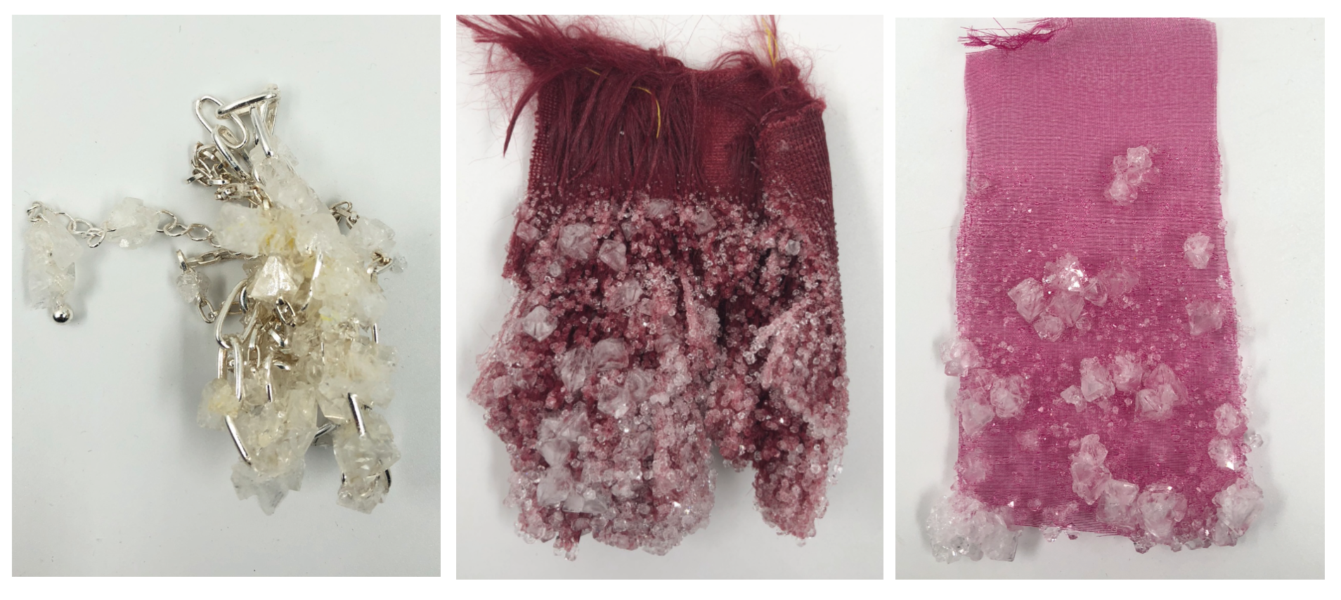
FABRICS: * Tule, synthetic hair, faux leather, silver chain
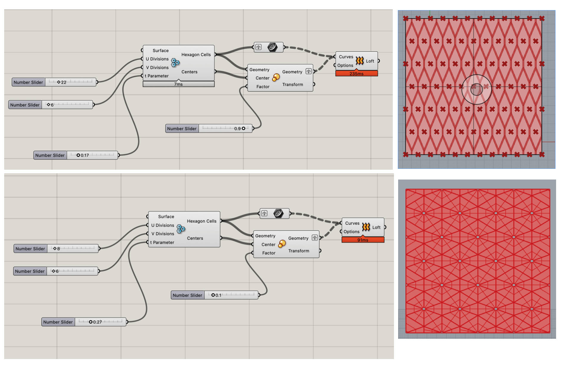
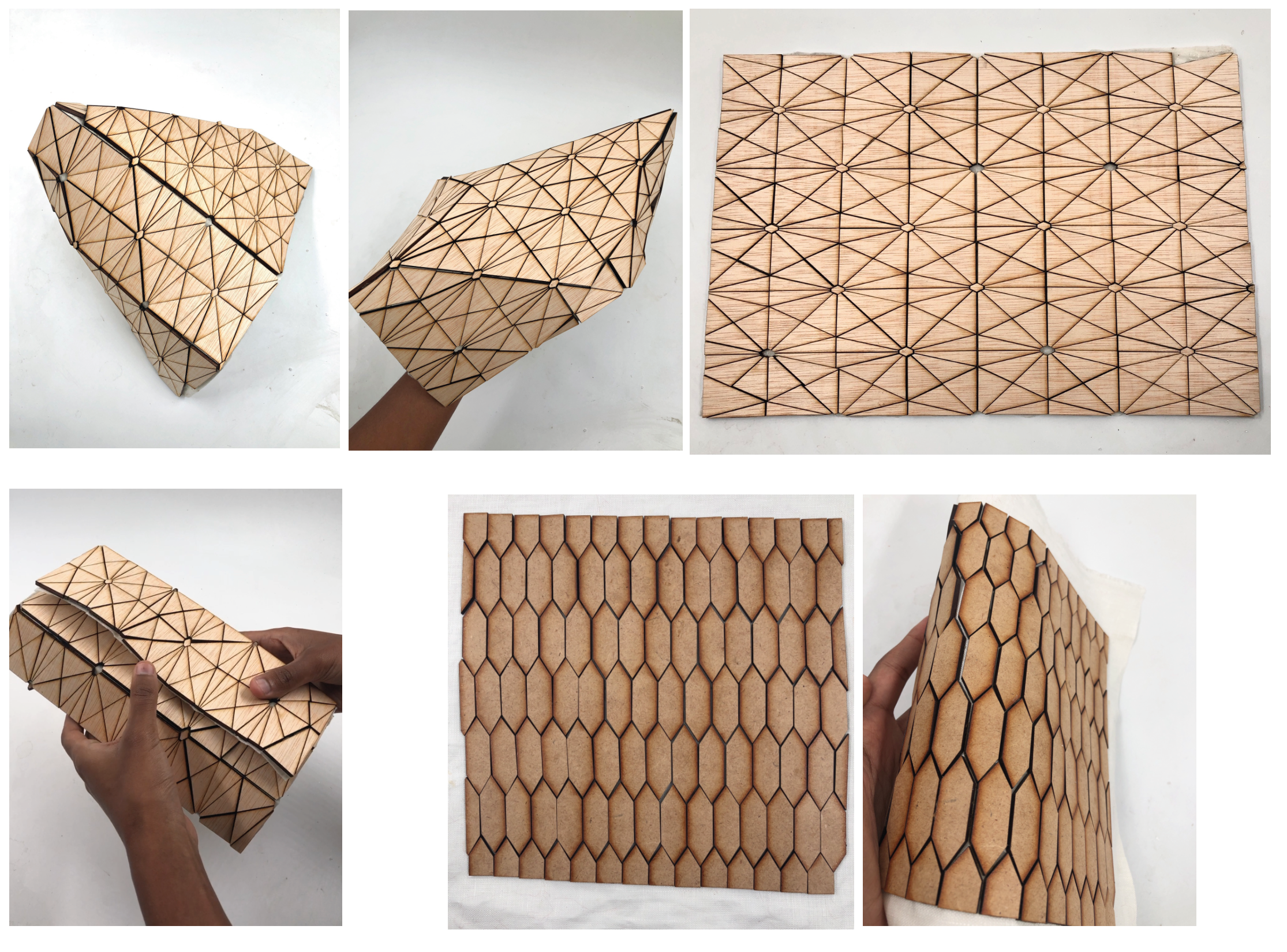
TEXTILEWOOD I worked on a gasshopper definition definition to laser cut wood and glue it on fabric. The final result would have been better if the wood pieces were not so close together, the are 3 mm thick, so the fabric would not bend so well.
Files
Research
CNC it is a subtractive manufacturing process that typically employs computerized controls and machine tools to remove layers of material from a stock piece and produces a custom-designed part. This process is suitable for a wide range of materials, including metals, plastics, wood, glass, foam, and composites.
The basic CNC machining process includes the following stages:
- Designing the CAD model
- Converting the CAD file to a CNC program
- Preparing the CNC machine
- Executing the machining operation
CNC how to set the parameters (This AMAZING explanation belongs to Annah but it´s so well explained that I wanted to use it as reference) *
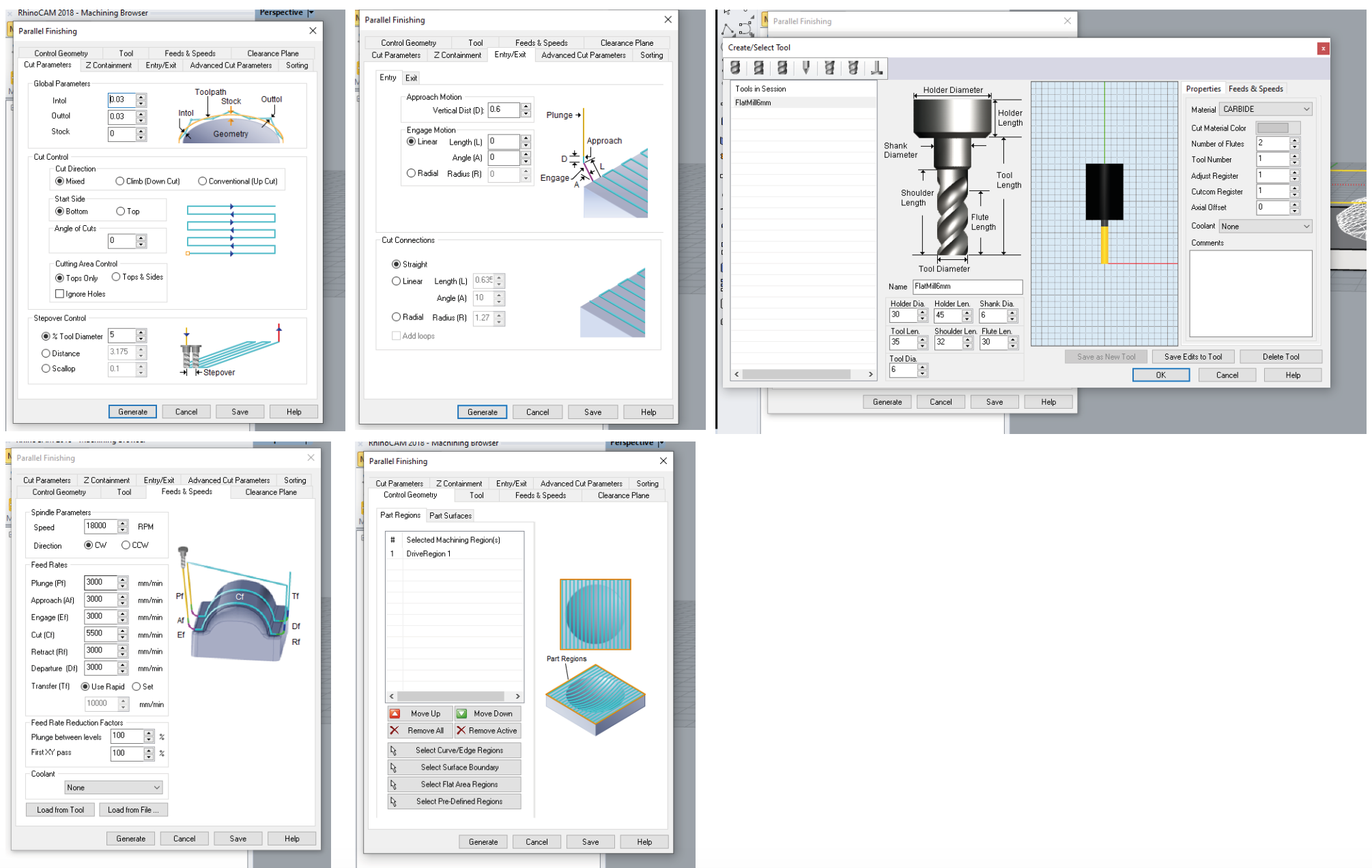
The milling of the mold should be done in two times: 1st the horizontal roughing which will give the global shape but not much defined and then the finishing will give more definition to it. For the horizontal roughing, open the plugin and click on Stock > Box Stock. Define the size of the model, which can be made more easily with a bounding box. Then, select Machine Operations > 3 axis adv Horizontal roughing. A window with multiple tabs will appear. - Control geometry: select curve/edges region by selectig the 2D bounding box of the object (from the surface - Tool: in this tab, you should document all the information about the mill you are about to use by clicking on Edit/select tool. The tool should be seected accordingly to the material you want to mill, the definition you desire and the amount of material to remove. Not only the properties should be documented, but also the feeds and speeds that need to be calculated. The feed rate kind of defines the speed of the CNC. It can be calculated as Feed Rate = RPM x Number of Flutes x Chip Load. The spinder of we have in the lab can go from 18000 to 24000 RPM for the spinder of the lab. The chip loasd depends on the material and the diameter of the endmill. These parameters are given by the vendor. The "cut" speed is actually the only one for the milling, all the other ones are for touching the material, entering it or getting out of it. We usually put a lower value for these ones. - Feeds and Speed: just press "Load from tool" and it should work if you did the previous parameter well. - Clearance plane: is where you should put a z offset (around 10mm is ok) so that the mill does not leave traces when traveling from one point to another. - Cut parameters: for the roughing steps, a stock of 0.6 should be put in order not to mill too much the final structure. Tick offset, direction: mixed, start point : inside, and a stepover distance that should not exceed 35%. - Cut levels: the stepdown control should never be more than 50% of the diameter if we do not want to dammage and overheat the mill. Tick depth first to save some time. - Engage/Retract: always select Path. Generate the path. Now you have the file you need for the horizontal roughing. * The Parallel finishing path can be generated only after the path of the Roughing is generated. Usually, the mill is changed from one step to the other so the parameters of the new tool should be input. The stepover control should be smaller to have a better definition (about 25%). * Once the two paths are generated, they can be exported as G files by righ clicking on the files and selecting post. A G file is a file with different types of instructions for the CNC milling machine.
Types of Mills
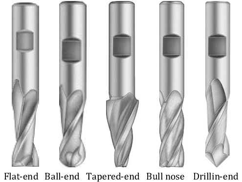
downcut n-mill upcut n-mill ...
Feed rate; speed at which we will be cutting The feed rate = RPM (revolutions for minute) X Number Flutes x Chip Load (mix between the diameter of th en mill and the material we wanna use) RPM = 18K - 24K CL= 0.279 - 0.33 inchesx25.4 =mm RMP= 18000 X 1 X 0.279 = 5000mm/min RMP = 18000 X 1 X 0.33 = 5900mm/min
conventional milling and climb milling EXPLANATION
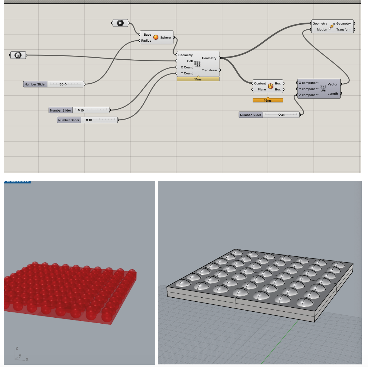
CNC MODEL IDEA 1 WITH GRASSHOPPER
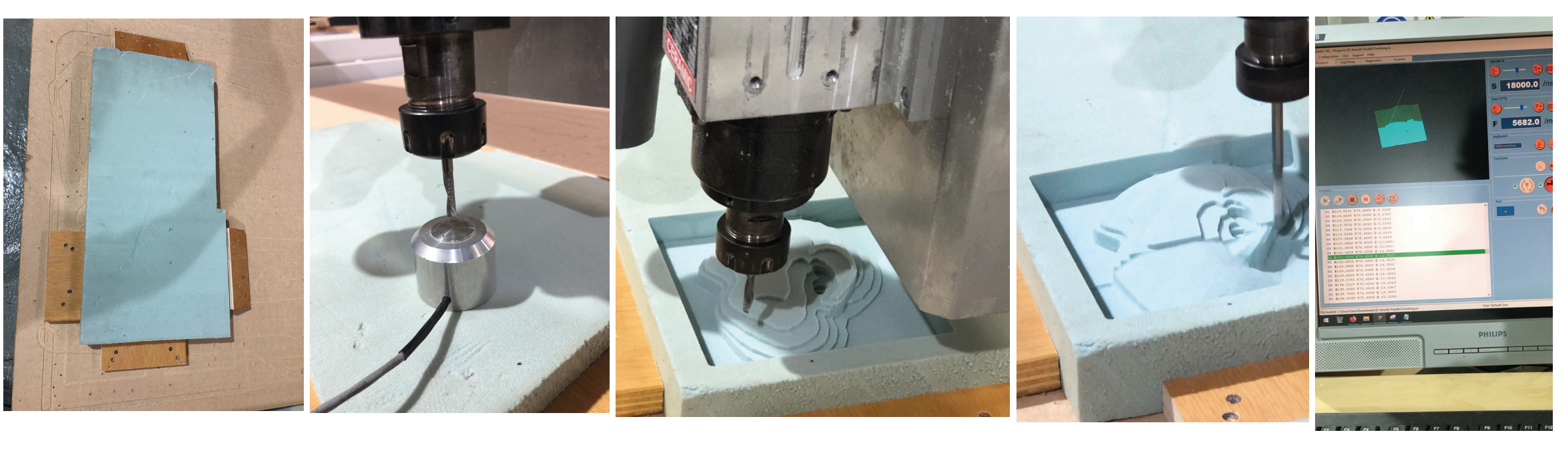
 CNC FINAL MODEL (EAR)

PARALLEL FINISHING
CNC MACHINE PREPARATION
VACCUM AND LEATHER MOLDING
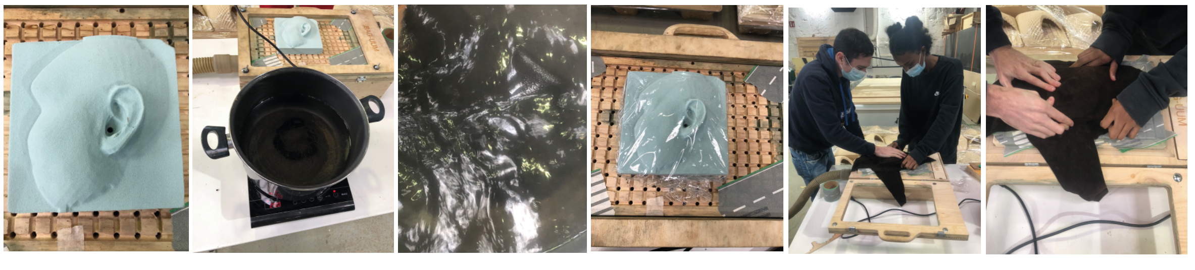
VACCUM, HOW IT WORKS?