5. E-textiles
Research
The history of smart textiles—also known as e-textiles or intelligent fabrics—can be traced back to the late 20th century, when advances in material science, electronics, and computing began to merge with traditional textile manufacturing. Early developments in the 1980s and 1990s focused on embedding conductive fibers and sensors into fabrics for military and medical applications, such as monitoring soldiers’ vital signs or patients’ physiological data. One of the earliest examples was the “Wearable Motherboard,” developed in the 1990s at the Georgia Institute of Technology, which integrated optical fibers into clothing for health monitoring. As microelectronics became smaller, more flexible, and energy-efficient, the 2000s saw the rise of commercial interest in smart fabrics for sportswear, fashion, and everyday technology. Companies and research institutions explored ways to create fabrics that could sense, react, and even adapt to environmental conditions. Today, smart textiles encompass a broad range of innovations—from self-heating and color-changing materials to fabrics that generate energy or connect to digital networks—reflecting the ongoing convergence of textiles, nanotechnology, and the Internet of Things (IoT). This evolution marks a shift from passive garments to interactive, responsive systems that redefine the relationship between humans, technology, and clothing.
References & Inspiration
I have been deeply inspired by Kasia Molga and her innovative approach to creating interactive and responsive garments, as well as by the artist behind Tapis Magique, whose work integrates smart textiles with choreography. Molga’s creations captivate me because they transform garments into living systems that react to the wearer’s body and environment, turning technology into a tool for emotional and sensory expression. Similarly, Tapis Magique fascinates me for how it bridges the worlds of movement and technology, using smart fabrics to visualize the dialogue between the human body and its surroundings through dance. Both artists push the boundaries of what textiles can do, showing that fabric can not only clothe or protect us but also communicate, move, and respond in deeply expressive ways. Their work inspires me to explore how electronic textiles can become a medium of artistic collaboration between human gesture, material, and technology.


Image reference: Cute Circuit brand creates clothes that light up because of music
Assignment
- Build at least one digital and one analog soft sensor.
- Document the sensor project as well as the readings got using the Analog Read of Arduino.
- Integrate the two soft sensors into one or two textile swatches using hard soft connections.
- Document the circuit and its schematics.
- Document your swatches/samples.
- Upload your Arduino code as text.
- Upload a small video of the swatches functioning.
- Integrate the swatch into a project (extra credit).
Tools & Components
- Arduino UNO
- Arduino IDE 2.3.6
- Multimeter
- Conductive thread and a needle
- Conductive tape
- Snaps
- 5v coin battery
- 1 sewable LED
- Scissors
- 1 embroidery hoop
- Wires, jumpers, breadboard
- Fabric: Gray, black and red felt
Process and workflow
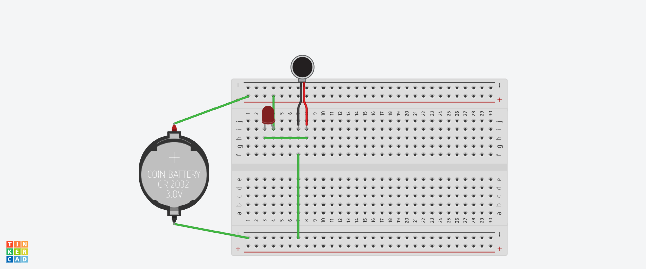
To connect a basic switch circuit, start by identifying your power source in this case a battery, a LED, and the switch. Connect one terminal of the battery to one terminal of the switch using a wire. Then, connect the other terminal of the switch to one side of the LED. Finally, connect the other side of the LED back to the remaining terminal of the battery, completing the circuit. When the switch is turned on, it closes the circuit and allows current to flow, lighting the LED; when turned off, it opens the circuit and stops the current.
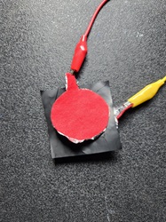
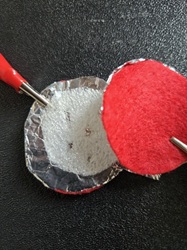
Using felt, aluminium paper and velostat, I created an analog pressure sensor (left picture) and a digital button in the right, without the velostat and using perforated foam in the middle.
- Right- Textile Button - Digital Input
- Left- Textile Pressure Sensor - Analog Input
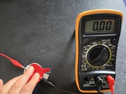
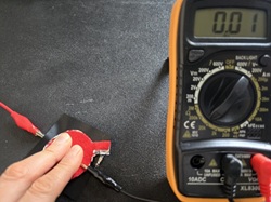
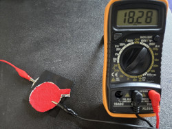
Digital and Analog buttons testing continuity with the multimeter. Using the resistance scale, without pressing the result in the multimeter is 18.28k. When pressing is 0.
Programming with Arduino - Digital Sensor to control an LED
This schemes were obtained from Emma Pareschi Arduino tutorials
Digital Switch Serial Monitor using Arduino, scheme, circuit and output
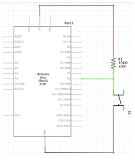

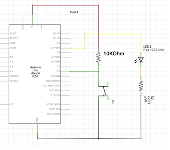
Digital Sensor and a Led using Arduino, scheme, and circuit

Code
int digital_sensor_pin = 8;
int digital_sensor_value = 0;

Sketch_Digital_Sensor

void setup() {
  // put your setup code here, to run once:
pinMode(digital_sensor_pin, INPUT);
Serial.begin(9600);
}

void loop() {
  // put your main code here, to run repeatedly:
digital_sensor_value = digitalRead(digital_sensor_pin);
Serial.println(digital_sensor_value);
delay(100);
}
Sketch_Digital_Sensor_Led

int digital_sensor_pin = 8;
int digital_sensor_value = 0;
int led_pin = 3;


void setup() {
  // put your setup code here, to run once:
pinMode(digital_sensor_pin, INPUT);
Serial.begin(9600);
pinMode(led_pin, OUTPUT);
}

void loop() {
  // put your main code here, to run repeatedly:
 digital_sensor_value = digitalRead(digital_sensor_pin);

 if(digital_sensor_value ==HIGH){
    digitalWrite(led_pin, HIGH);
  }
  else {
     digitalWrite(led_pin, LOW);
     }
}
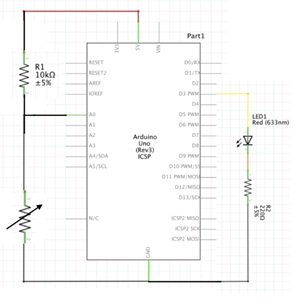
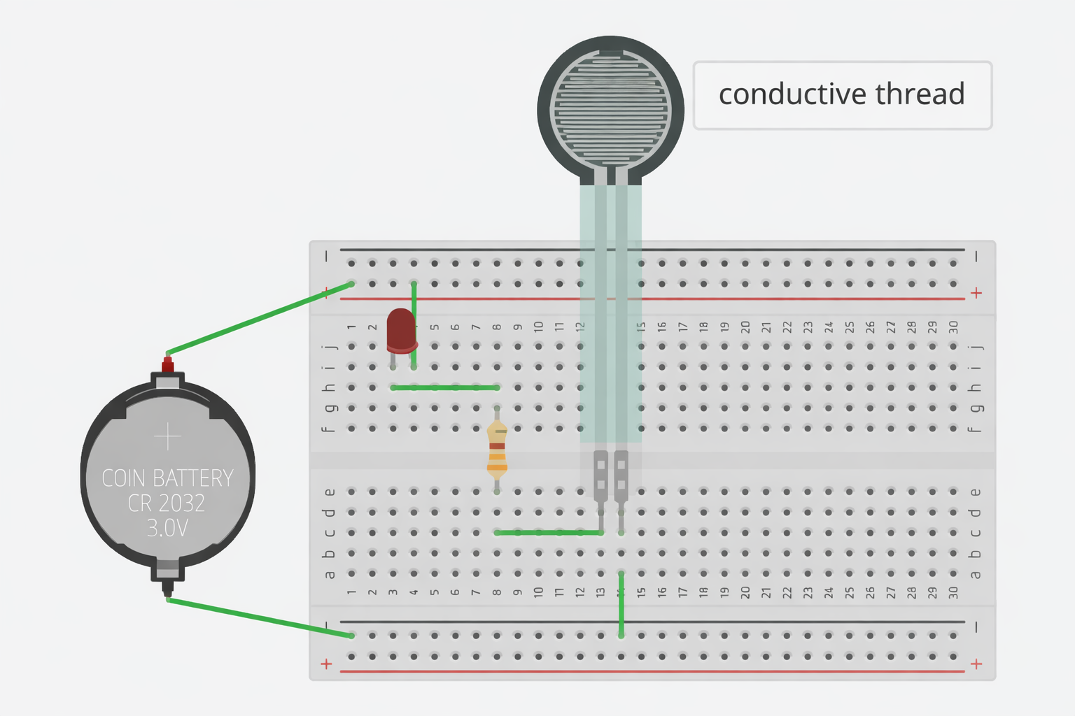
Programming with Arduino - Analog Sensor to control an LED
Analog Sensor and a Led using Arduino, scheme, and output

Code
Sketch_Analog_Sensor_Led

int analog_sensor_pin = A0;
int analog_sensor_value = 0;
int led_pin = 3;


void setup() {
  // put your setup code here, to run once:
pinMode(analog_sensor_pin, INPUT);
pinMode(led_pin, OUTPUT);
Serial.begin(9600);
}

void loop() {
  // put your main code here, to run repeatedly:
 analog_sensor_value = analogRead(analog_sensor_pin);
 analog_sensor_value = map(analog_sensor_value, 230, 130, 0, 255);
 analog_sensor_value = constrain(analog_sensor_value, 0, 255);

 analogWrite(led_pin, analog_sensor_value);
 Serial.println(analog_sensor_value);
 delay(10);
}
Textile Swatches
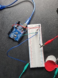
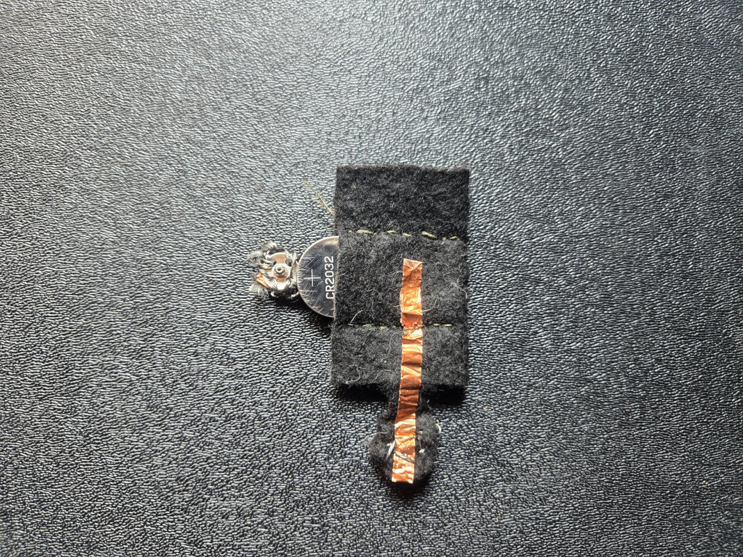
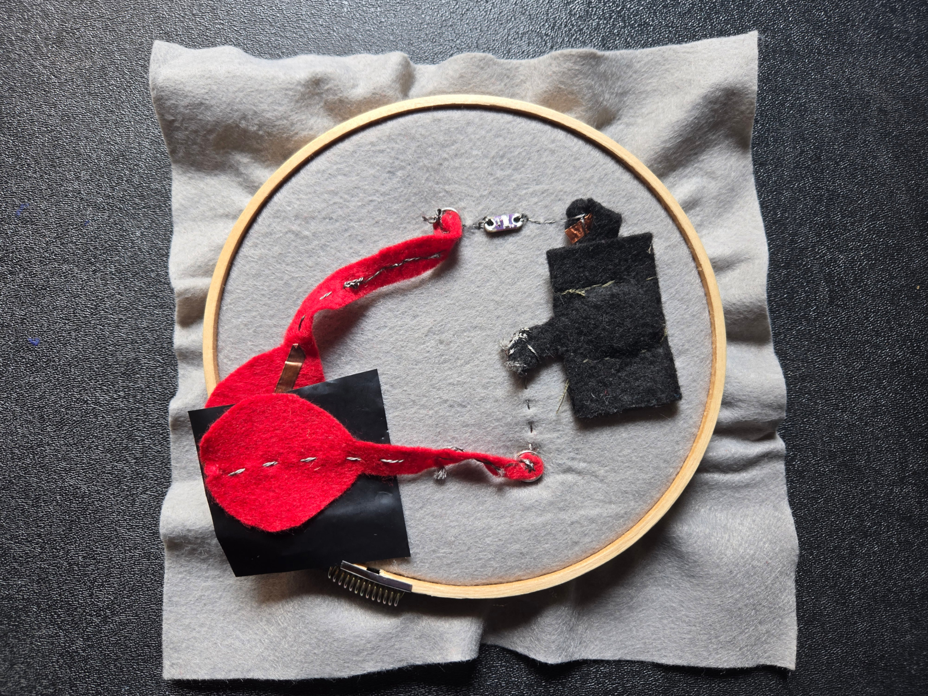
I started by cutting and sewing a 3 V coin cell battery holder to power the circuit, using a felt design with conductive tape.
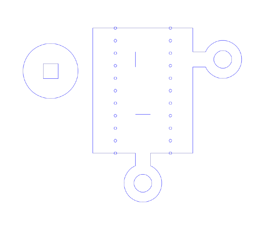
Circuit
Following the circuit shown below, I sewed the analog and digital textile sensors swatches.
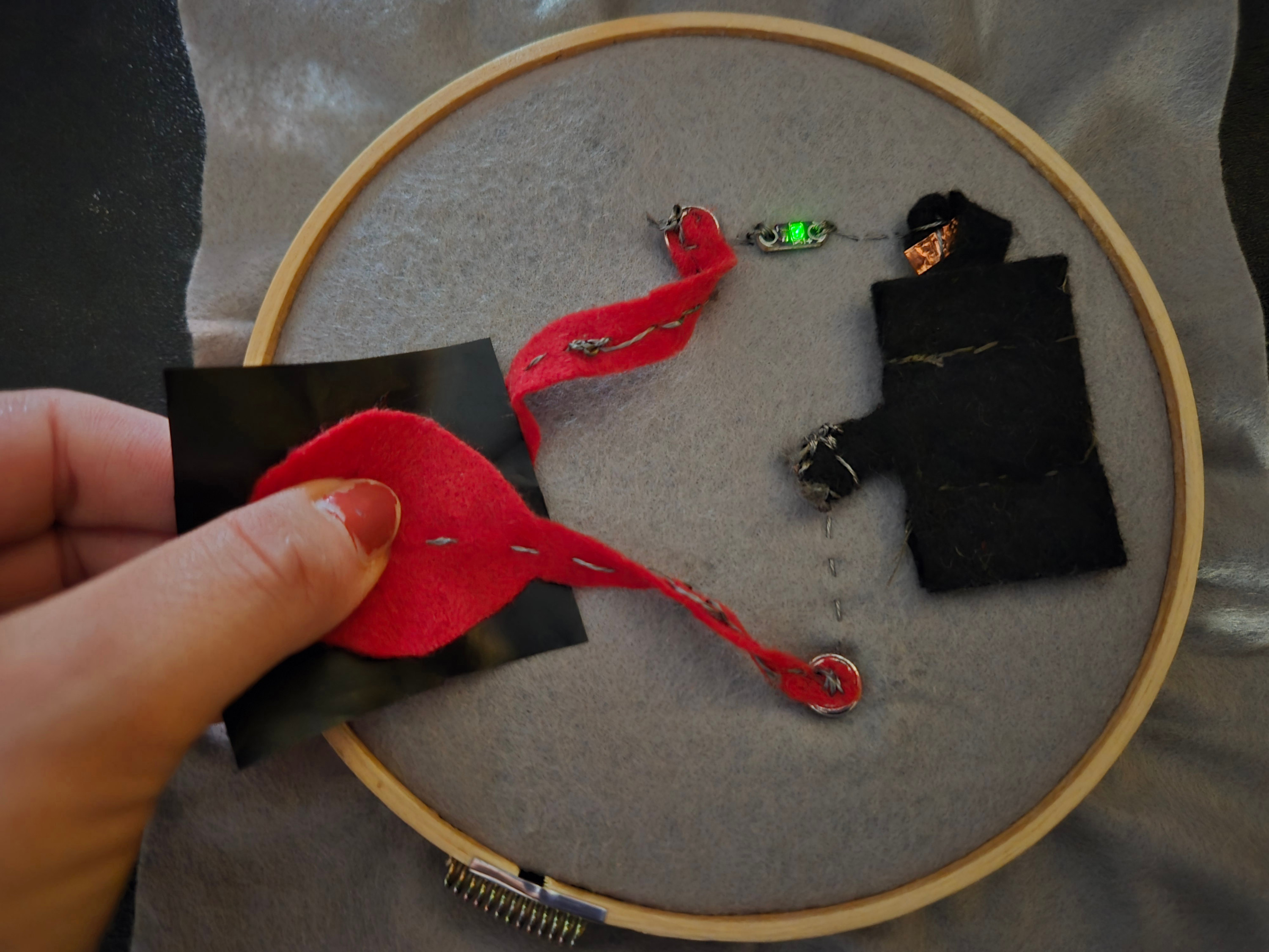
Textile Digital Sensor
To create the digital sensor, I used conductive tape inside the felt switch and placed perforated foam in the middle, forming a sandwich structure. When the sensor was touched, the circuit closed and the LED turned on.
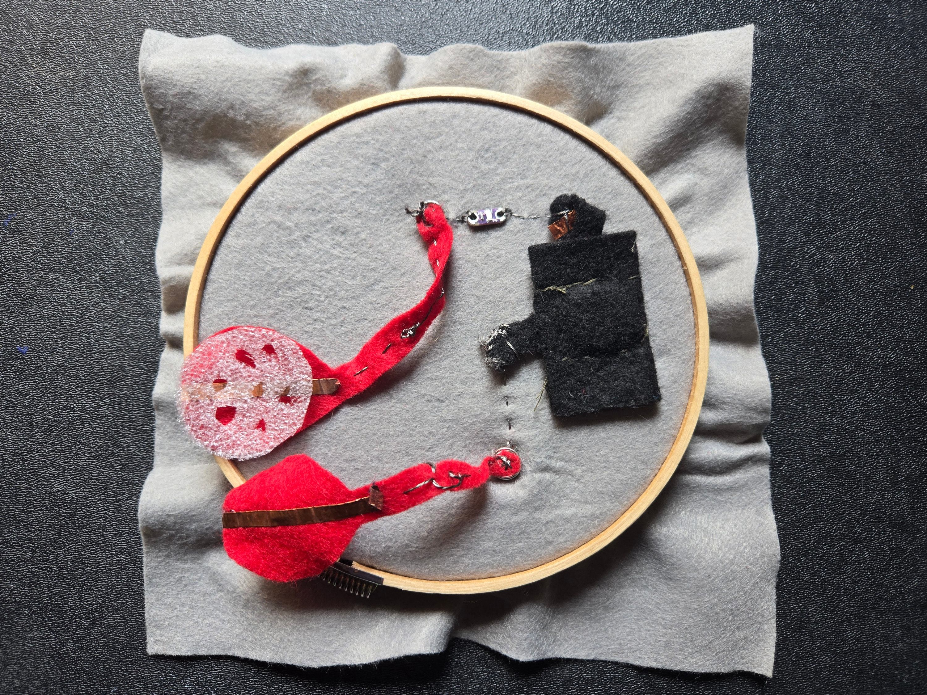
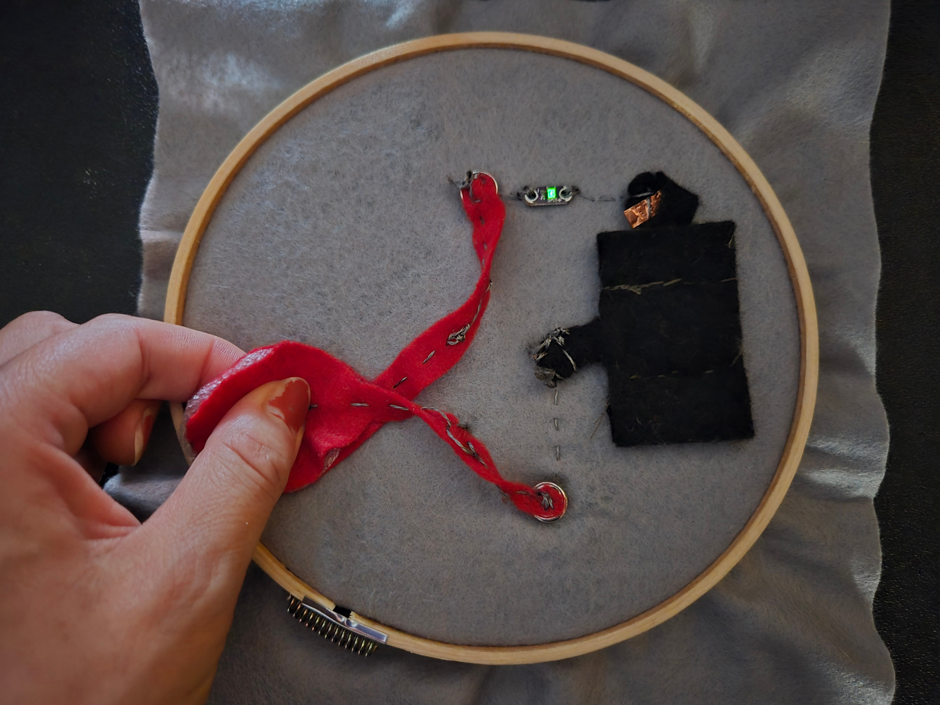
Textile Analog Sensor
The velostat reduces its resistance when pressure is applied, as shown in the image and further demonstrated in the video. As the applied pressure increases, the LED becomes brighter.
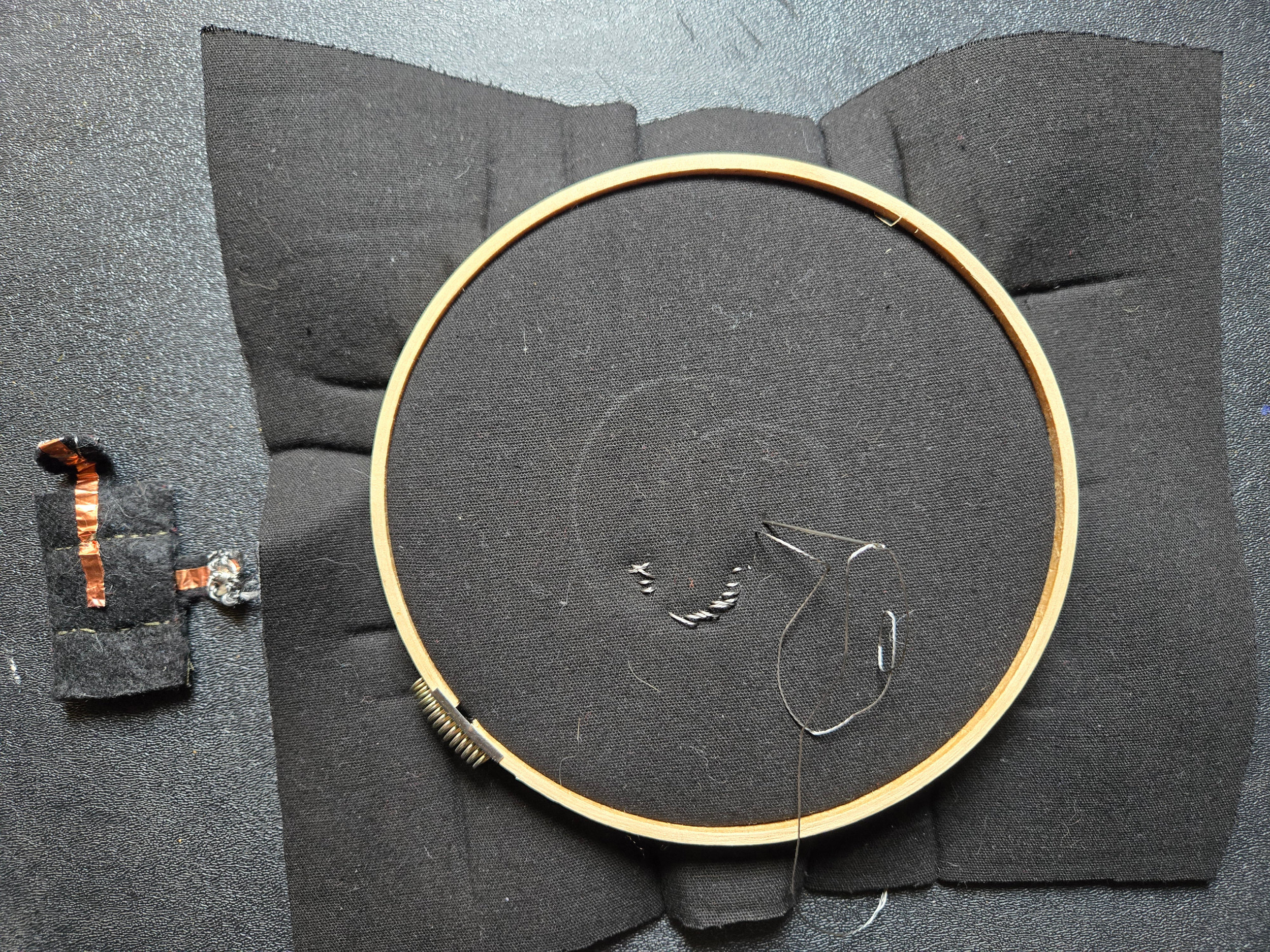
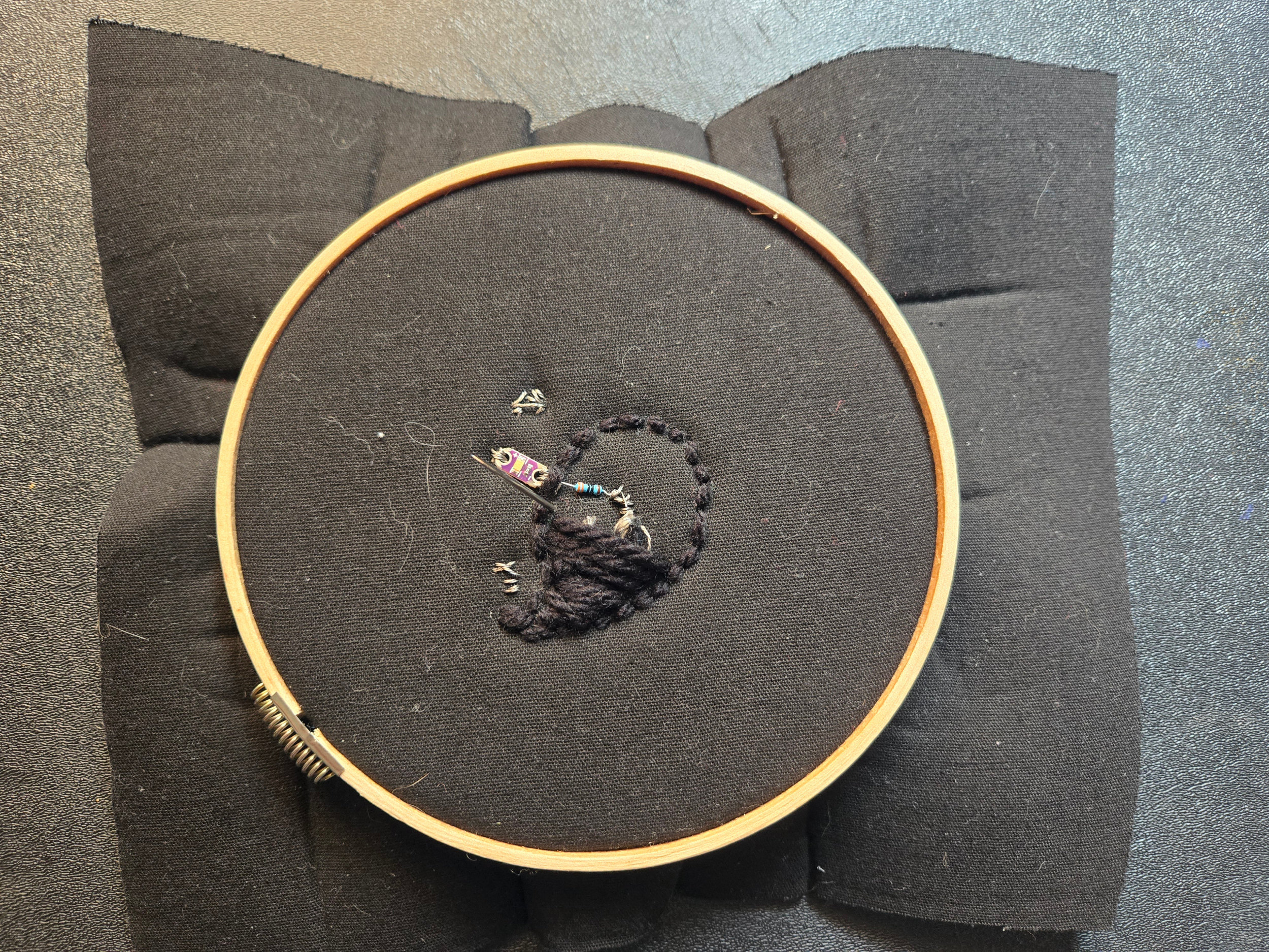
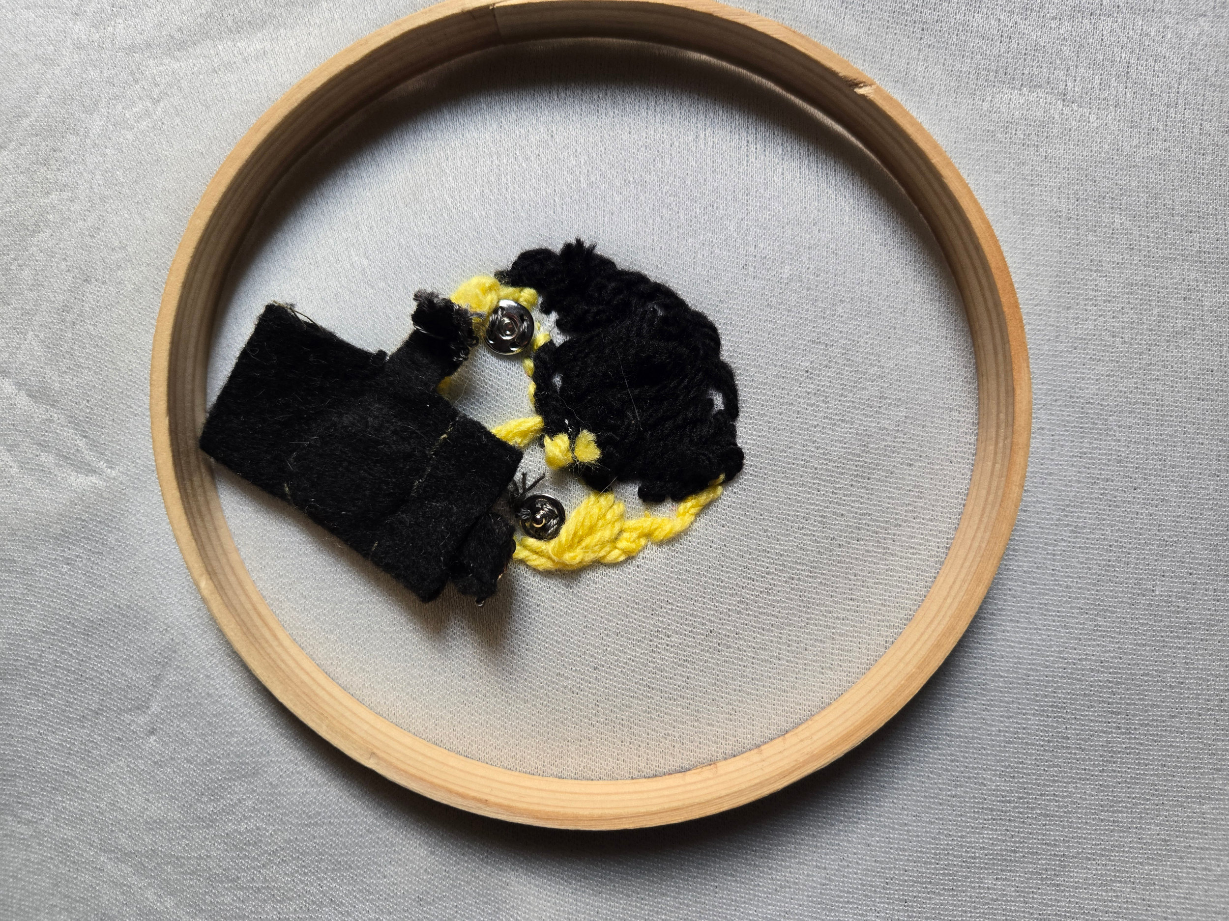
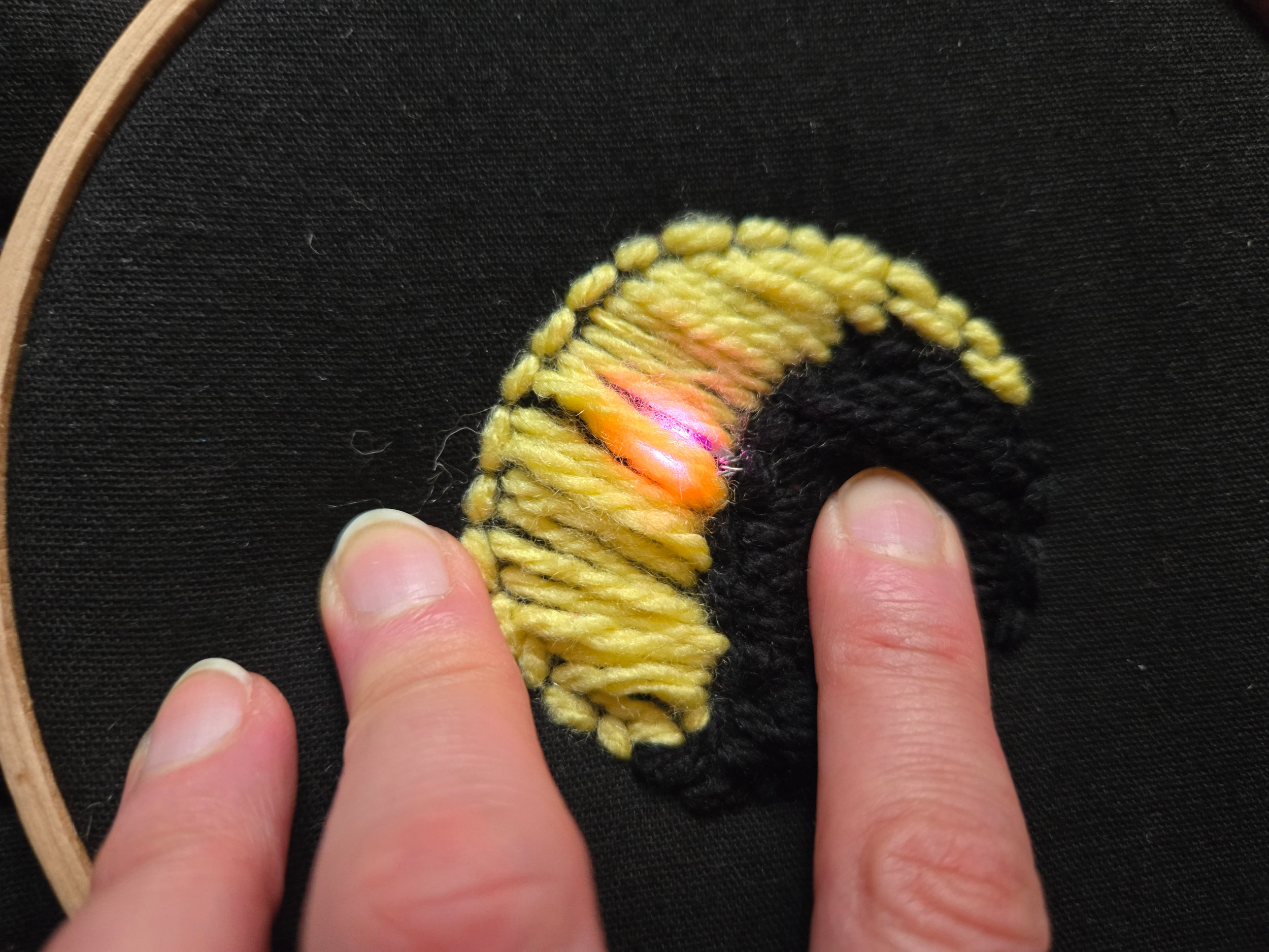
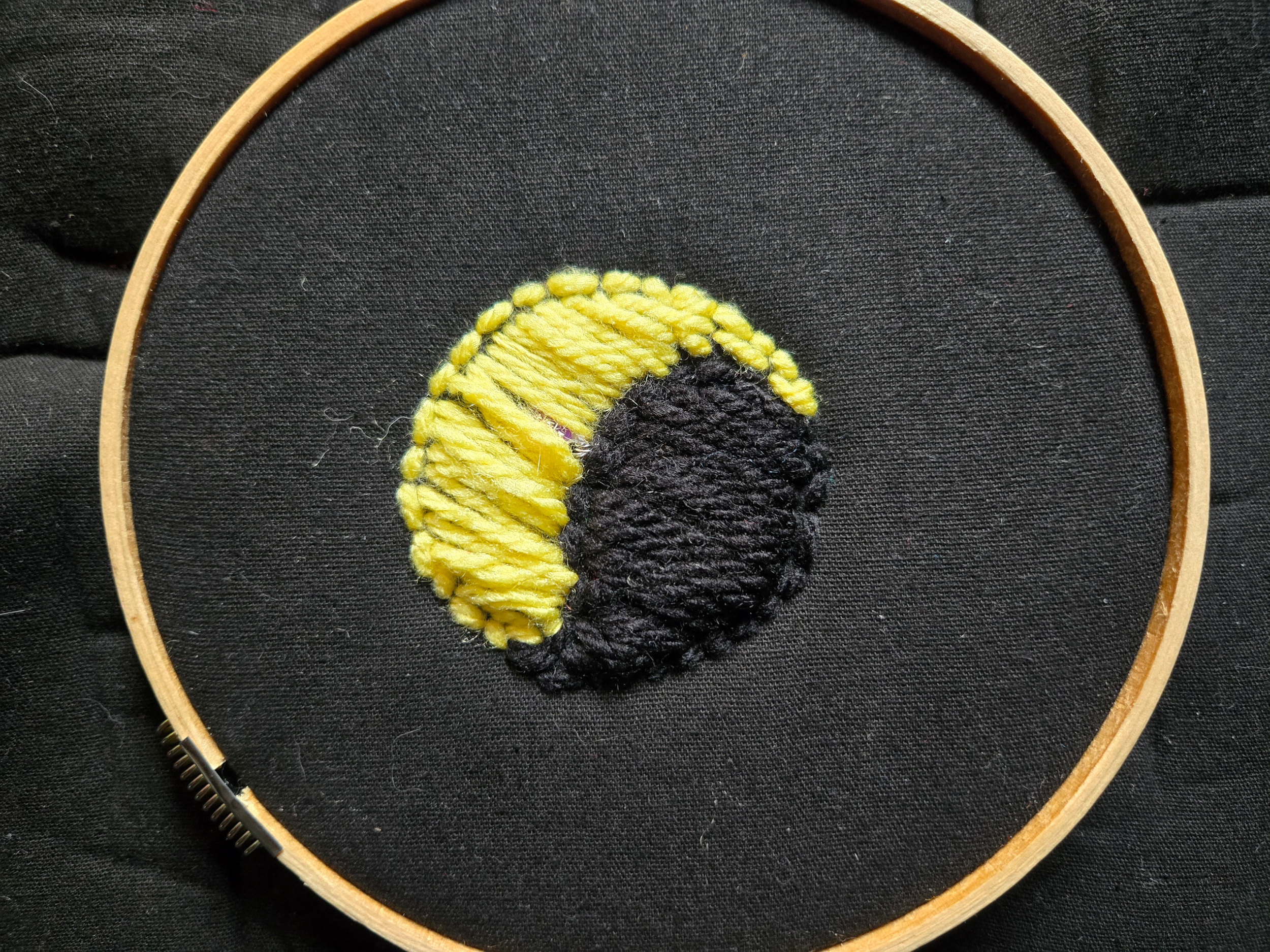
Project - Yin-Yang touch embroidered sensor
To apply what I learned in the e-textiles lecture, I decided to embroider a touch sensor to turn on an LED. It could be later integrated it into a purse that lights up when touched. This could be useful at night.
Tools & Components
- Scissors
- Yellow and Black yarn
- 1 sewable LED
- 330 ohm resistor
- Conductive thread
- Fabric (bonded blanket)
- 5v coin battery
- Snaps
- Conductive tape
Circuit
The sensor in my project is made using conductive thread wrapped around one of the yarns. When a finger touches the center of the black side of the yin-yang, the circuit is closed and the LED turns on.
Process
I began by drawing the ying-yang shape and sewing the LED, resistor, and snaps for the positive and negative battery connections. I then sewed the battery pouch and used conductive tape to connect the snaps. After that, I used yarn to cover the electronic components and create the yin-yang appearance.
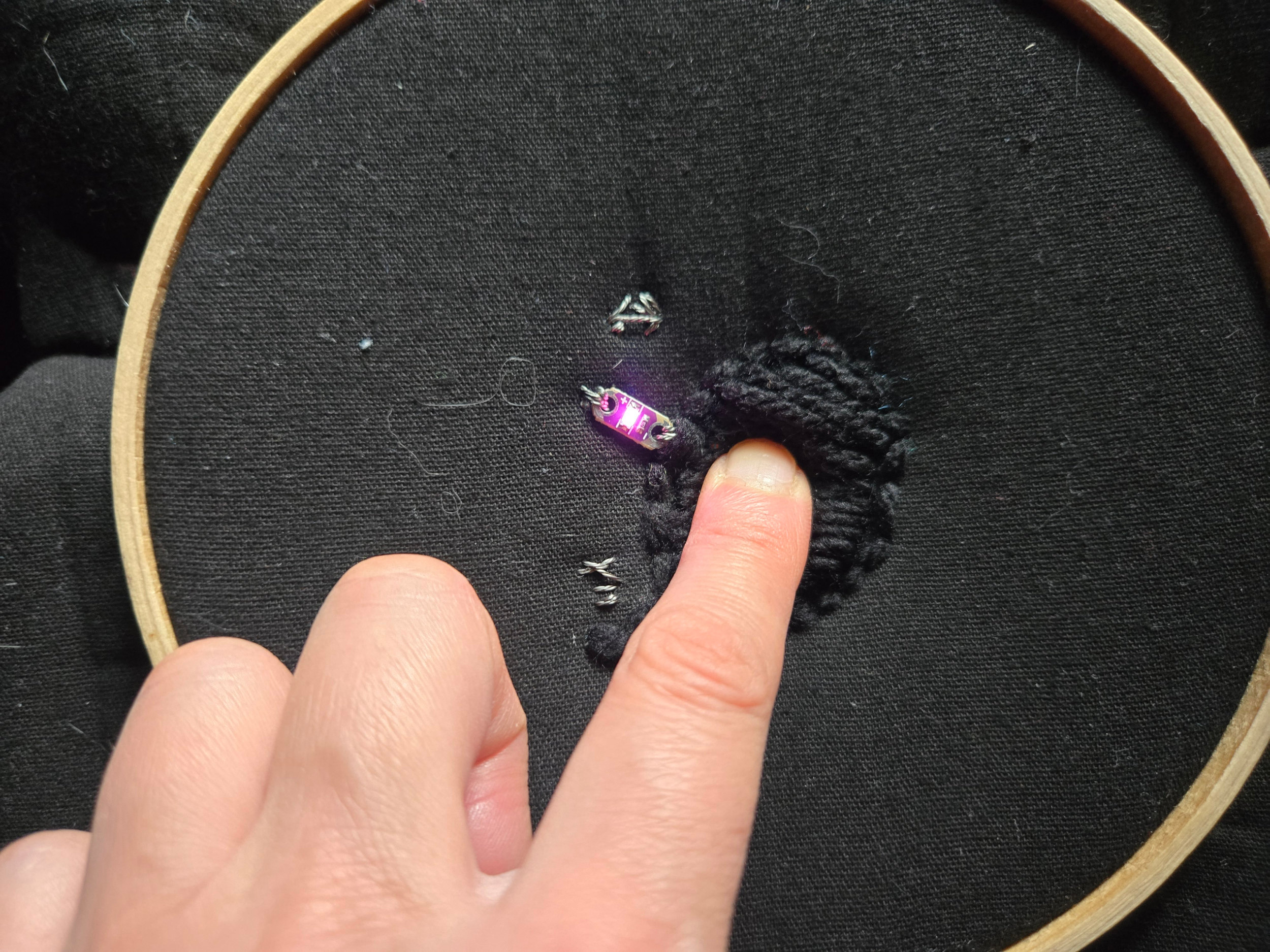
Result
Learning Outcome and Observations
Working with sensors and programming an Arduino Uno was quite interesting. I was particularly drawn to the idea of using a zipper as a switch, so I attempted to develop it as a project, but it did not work as expected.
It was a challenging process. In my first attempt, I sewed the conductive thread too tightly and too close to the zipper, which prevented it from opening. In the second attempt, the thread was placed too far from the zipper, so it did not conduct properly.
Links
Tufting With Conductive Thread
Arduino Capacitive Sensor in Less Than 2 Minutes