Deliverables
Gantt Diagram
BOM
Slide show
Grattitude Loom Final Presentation by Pattaraporn Kittisapkajon
Story telling script
At first, I was simply planning to create a video that explained what the project was and how it became Gratitude Loom. However, my mentor Louise suggested something that completely shifted my approach: the video itself should become the ritual.
I immediately connected with this idea. Instead of creating a conventional explanatory presentation, I began developing the storyboard around the feeling of the experience itself — focusing on mood, pacing, sound, rhythm, and atmosphere. I wanted the viewer to slowly enter the world of the loom rather than just intellectually understand it.
Gratitude Loom Storyboard by Pattaraporn Kittisapkajon
How-Tos & Tutorials
What you'll need
Hardware
- 4-shaft table loom (any will work, but the sensor mounts are tuned for a Schacht-sized frame)
- Raspberry Pi 4 (4GB or 8GB)
- 7× Hall effect sensors (A3144 or similar — digital output)
- 7× small neodymium magnets (6mm × 3mm)
- Resistors for voltage dividers (10kΩ and 20kΩ pairs, one per sensor)
- Breadboard or perf board, hookup wire, JST connectors
- USB powered speaker (a small plug-and-play USB speaker is fine — no external amplifier needed)
- USB microphone
- 5" 800×480 HDMI touchscreen (connects via HDMI for display + USB for touch)
- Pi 4 power supply, microSD card (32GB+), case with cooling
- Noctua NF-A4x10 5V on Raspberry PI Software
- Raspberry Pi OS (64-bit)
- Python 3.11+
- VS Code (with Remote-SSH extension)
- Groq API key (free tier works)
- Orpheus TTS Tools
- 3D printer (PLA is fine)
- Soldering iron
- Wire strippers, heat shrink
-
Multimeter (for checking divider outputs before plugging into the Pi)
Check out my Bill of Materials (BOM) for links to the specific components and materials used in this project.
1. Wiring the Hardware
Before any wiring, here's everything that goes into the loom and what each piece does:
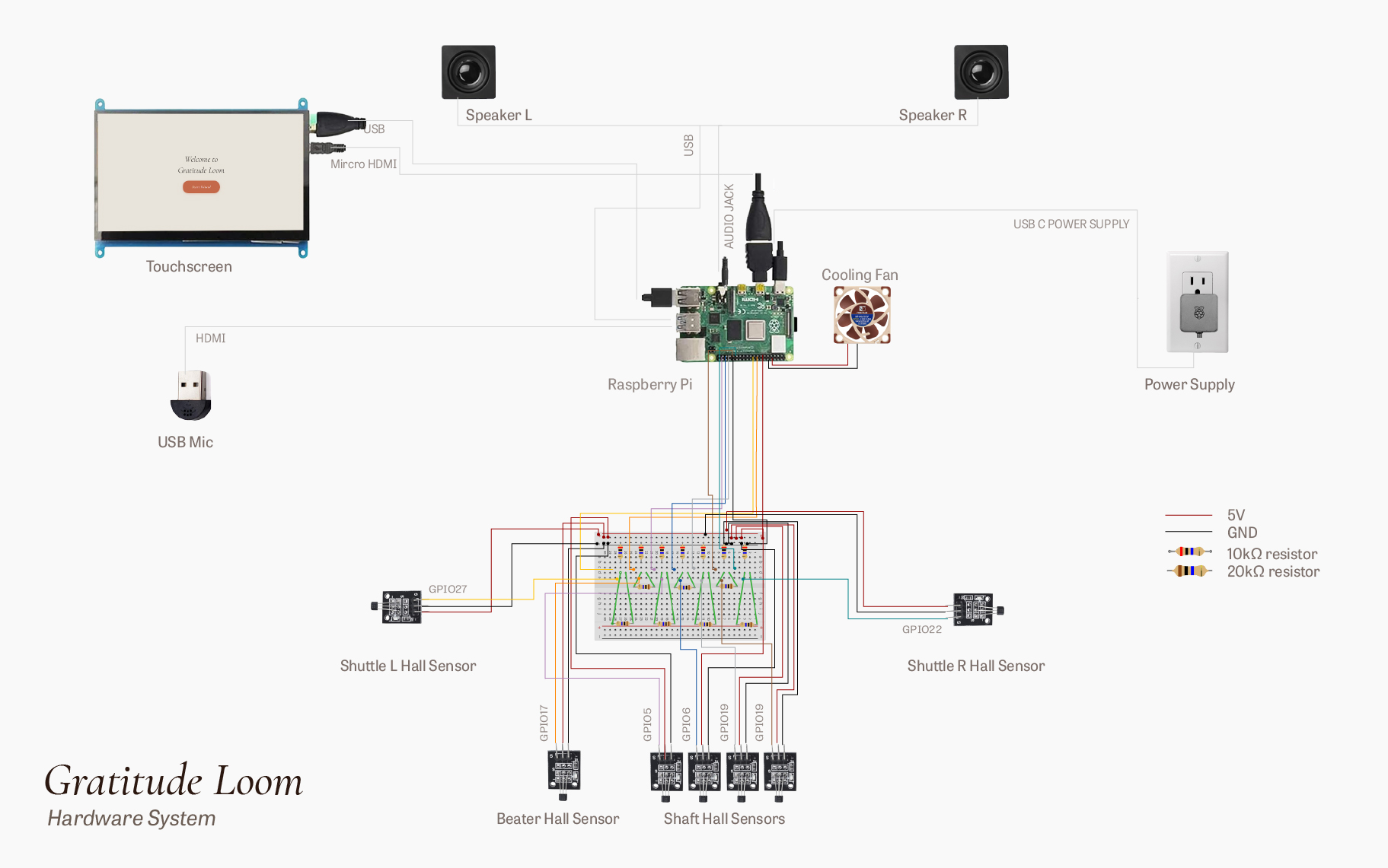
Hardware System Diagram — Pattaraporn (Porpla) Kittisapkajon
| Component | Qty | What it does | Connects to |
|---|---|---|---|
| Raspberry Pi 4 | 1 | The brain. Reads sensors, runs the Python loop, calls Groq, plays Diana's voice. | — |
| Hall effect sensor (A3144) | 7 | Detects when a magnet passes nearby. Outputs a digital signal. | Pi GPIO (via voltage divider) |
| Neodymium magnet (6mm × 3mm) | 7 | Pairs with each sensor. Mounted on moving parts of the loom. | Beater, shuttle, shaft levers |
| 10kΩ resistor | 7 | Top half of the voltage divider — drops 5V signal to safe levels for the Pi. | Between sensor signal and Pi GPIO |
| 20kΩ resistor | 7 | Bottom half of the voltage divider — to ground. | Between Pi GPIO line and ground |
| Perf board / breadboard | 1 | Holds all seven voltage dividers in one tidy place. | Sensors in, ribbon out to Pi |
| Hookup wire + JST connectors | — | Connects sensors to the divider board and the board to the Pi. | Throughout |
| USB speaker | 1 | Plays Diana's voice. | Pi USB port |
| USB microphone | 1 | Captures voice input. | Pi USB port |
| 5" HDMI touchscreen (800×480) | 1 | Shows the interface and accepts touch input. | Pi micro-HDMI + USB |
| microSD card (32GB+) | 1 | Stores the Pi's operating system and the project code. | Pi SD slot |
| Pi power supply (5V 3A USB-C) | 1 | Powers everything. | Pi USB-C port |
| Noctua NF-A4x10 5V | 1 | Keep the PI cool | Pi 5V and GND |
The A3144 Hall effect sensor runs on 5V and outputs a 5V signal when it detects a magnet. The Raspberry Pi’s GPIO pins can only safely read 3.3V. A voltage divider uses two resistors to trim the signal down — no special chip, just a tug of war between resistance values.
Drag the sliders to experiment — set R1 to 0 and Vout jumps to full input voltage, which would damage the Pi. Each of the 7 loom sensors gets its own R1 + R2 pair. All sensors share a common 5V and GND rail on the breadboard.
Build seven of these. I'd recommend a small perf board with all seven dividers, labeled, with JST headers going out to each sensor and a ribbon going to the Pi.
Pin mapping
Assign each sensor to a free GPIO pin. Keep a list — you'll reference it in the code. A workable layout:
| Sensor | GPIO |
|---|---|
| Beater | 17 |
| Shuttle dock L | 27 |
| Shuttle dock R | 22 |
| Shaft 1 | 5 |
| Shaft 2 | 6 |
| Shaft 3 | 13 |
| Shaft 4 | 19 |
All sensor power lines go to the Pi's 5V rail. All grounds to a common ground. Use enable internal pull-ups in software, but the divider itself sets the voltage.
Connecting the peripherals
Three things plug into the Pi alongside the sensor board: a speaker, a microphone, and a display.
- USB speaker — this speaker uses two connections: a USB cable for power a 3.5mm audio jack connected to the Raspberry Pi's headphone output for sound
- USB microphone — plug into any USB port. Used for voice input to the system. Any plug-and-play USB mic works; you don't need a studio condenser. A small lavalier or desktop mic is plenty.
- 5" HDMI touchscreen (800×480) — two cables: a micro-HDMI to HDMI from the Pi's HDMI0 port (closest to the power input) to the screen for video, and a USB cable from the screen to the Pi for touch input. The screen draws its power over the same USB cable. No driver install needed on Raspberry Pi OS — it should light up on boot. Once everything is plugged in, verify each device is recognized:
lsusb              # lists all USB devices — confirm mic and speaker are there
aplay -l           # lists audio output devices — confirm speaker
arecord -l         # lists audio input devices — confirm mic
Write down the card numbers for the speaker and the mic. You'll reference them in the audio setup in Section 2.
2. Setting Up the Pi
Flash the OS
Download Raspberry Pi Imager from raspberrypi.com/software and install it on your laptop. Insert your microSD card using a USB adapter.
Open Pi Imager: - Choose Device: Raspberry Pi 4 - Choose OS: Raspberry Pi OS (64-bit) — the default version with desktop - Choose Storage: your microSD card Before you click "Write," click the gear icon at the bottom right (or the "Edit Settings" button). This screen is the whole point of modern Pi setup — it lets you pre-configure everything so the Pi can join your network and accept connections from your laptop the moment it boots, without ever needing to plug in a keyboard.
Walk through each section:
Hostname
Set it to loom (or whatever you want — short and memorable). This is the name your laptop uses to find the Pi on the network. Instead of hunting for an IP address every time, you'll just type loom.local. If you set it to something else, use that name everywhere loom.local appears in this guide.
Username and password
Pick a username — keep it simple, lowercase, no spaces (e.g., porpla). Pick a password you'll actually remember, because you'll type both every time you SSH in. Write them down somewhere. If you forget the password, the only fix is to re-flash the SD card.
Wireless LAN
- SSID: your WiFi network name, exactly as it appears (case-sensitive, including spaces)
- Password: your WiFi password
-
Wireless LAN country: your two-letter country code (
US,TH, etc.). The Pi needs this to know which WiFi channels are legal in your country — without it, WiFi sometimes refuses to connect at all. Locale settings -
Time zone: pick yours from the dropdown (e.g.,
America/New_York,Asia/Bangkok) -
Keyboard layout:
us(or whatever matches your physical keyboard) Services tab -
Check Enable SSH. SSH is the protocol that lets your laptop talk to the Pi over the network. Without it, the Pi is a closed box you can only use with a keyboard and monitor.
-
Select Use password authentication. Simpler than setting up SSH keys, and fine for a project like this. Options tab (optional but nice)
-
Check "Eject media when finished" so the SD card is safe to pull out the moment Imager is done. Save your settings. Click Write. Confirm. Wait about ten minutes for it to flash and verify.
First boot
Eject the SD card, slide it into the Pi. Plug in the touchscreen (HDMI + USB), the speaker, and the mic. Plug in power last — the Pi has no power switch, so plugging in power is how you turn it on.
First boot takes a few minutes. The Pi resizes its filesystem, joins your WiFi, and lands at the desktop. Let it finish.
Find the Pi on your network
From your laptop, open a terminal and run:
ping loom.local
If you see replies, the Pi is on the network and reachable by name. If ping hangs, log into your router's admin page, find the connected devices list, and look for the Pi — note its IP address (something like 192.168.1.42) and use that in place of loom.local for the rest of this section.
First SSH connection
From your laptop terminal:
ssh username@loom.local
Type "yes" to accept the fingerprint the first time. Enter your password. You should land at a prompt like username@loom:~$. You're now controlling the Pi from your laptop.
Update the system and install packages
While you're in the SSH session:
sudo apt update && sudo apt full-upgrade -y
sudo apt install -y git python3-pip python3-venv portaudio19-dev libsndfile1
This takes a while. When it's done: sudo reboot. The SSH session will drop. Wait a minute, then ssh back in.
Audio setup
The Pi has multiple audio devices (HDMI, headphone jack, USB speaker, USB mic). If you don't pin them explicitly, Orpheus and the system audio will fight each other and you'll get silence or static.
Run aplay -l to list output devices and arecord -l to list input devices. Identify your speaker and mic card numbers. Then edit /boot/firmware/config.txt:
dtparam=audio=on
And set the defaults in ~/.asoundrc — note both output (pcm.!default) and input (pcm.!default for capture is set via the same card value if it's a combined USB device, otherwise specify separately):
pcm.!default {
  type asym
  playback.pcm "plughw:1,0"   # speaker card number
  capture.pcm  "plughw:2,0"   # mic card number
}
ctl.!default {
  type hw
  card 1
}
Test output: aplay /usr/share/sounds/alsa/Front_Center.wav. You should hear it.
Test input: arecord -d 5 test.wav && aplay test.wav. Speak for five seconds, then play it back.
If both work, audio is done.
WiFi stability
Pi 4 WiFi can drop under load. Disable power management on the wireless interface:
sudo iwconfig wlan0 power off
Add this to /etc/rc.local or a systemd service so it persists across reboots.
Connect VS Code to the Pi
This is what makes everything that follows possible. You'll edit files from VS Code on your laptop, but the files live on the Pi and the code runs on the Pi.
- Install VS Code on your laptop from code.visualstudio.com.
- Open VS Code → Extensions panel (the squares icon on the left, or
Cmd/Ctrl + Shift + X). - Search for Remote - SSH (by Microsoft) and install it.
- Hit
F1(orCmd/Ctrl + Shift + P) to open the command palette. Type Remote-SSH: Connect to Host and press Enter. - Type
username@loom.local(using your actual username) and press Enter. - When asked about the platform, choose Linux.
- Enter your Pi password.
VS Code reloads. The bottom-left corner now shows "SSH: loom.local" — that's the signal you're connected. Open the integrated terminal (Terminal → New Terminal) and run
hostname. If it returnsloom, you're running commands on the Pi from inside VS Code.
You're ready to write code.
3. Coding in VS Studio Code
I have almost zero coding skill so I vibe code with Claude. It might be easier for you to chat with Claude to get what you want than to follow my code exactly — but here's a brief explanation of the structure so you know what you're looking at.
Project structure
The project lives in one folder, gratitude-loom, with several Python files. Each one handles a single piece of the system:
main.py— the entry point. The only file you actually run.sensors.py— sets up the GPIO pins and reads the seven Hall effect sensors.scores.py— calculates the rhythm score and the craft attentiveness score from sensor events.flow.py— the four-level flow state machine (Steady → Flowing → Absorbed → Generative).patterns.py— the 22-pattern 4×4 matrix Diana draws from.voice.py— handles Orpheus TTS calls (Diana's voice).groq_client.py— wraps the calls to Llama 3.3 for what Diana actually says.config.py— pin assignments, thresholds, file paths — the values you'd want to tweak. Onlymain.pyruns. It imports the rest and ties them together in one loop. Don't try to runsensors.pyorvoice.pyon their own — they're modules, not standalone programs.
How it works
The system runs on three ideas:
- Two scores — a rhythm score (how steady is your weaving?) and a craft attentiveness score (are you paying attention to the cloth?). Both update continuously from sensor events.
- Four flow levels — Steady, Flowing, Absorbed, Generative. The system moves between them based on the two scores over time. Where you are determines how Diana speaks.
- A 22-pattern 4×4 matrix — Diana picks from this matrix when she speaks. The patterns are organized by embodiment state (rows) and memory depth (columns), so what she says always reflects where you are in the weaving.
Both the LLM (Llama 3.3, which writes Diana's lines) and the TTS (Orpheus, which speaks them) run through the Groq API — one key, one library, no model weights stored locally on the Pi. Get a key from console.groq.com, drop it in a
.envfile asGROQ_API_KEY=..., and the project picks it up from there.
If you want to change something, start in config.py — most of the tweakable values live there. If you want a different character than Diana, edit the system prompt in groq_client.py and swap the voice in voice.py. The architecture doesn't depend on the persona — only on the rhythm.
Run it
python main.py
Press the beater. Sensor events log in the terminal. After about thirty seconds of steady weaving, Diana speaks.
4. 3D Print and Assemble
The printed parts hold the sensors and magnets in precise alignment with the existing structure and moving components of the loom. Each part was designed to be easily assembled and disassembled using peg-and-hole connections, allowing components to be replaced or adjusted without permanently altering the loom.
Fit testing took longer than expected. Even when using the same print settings, the tolerances were not always consistent, so many parts required multiple iterations before fitting correctly. This is still something I would like to improve in future versions.
Aesthetically, I wanted the loom to feel calm, quiet, and slightly wabi-sabi — something simple and grounded rather than overly technical. Due to time constraints, I kept the forms minimal and functional. Future iterations could become slimmer, lighter, and easier to transport.
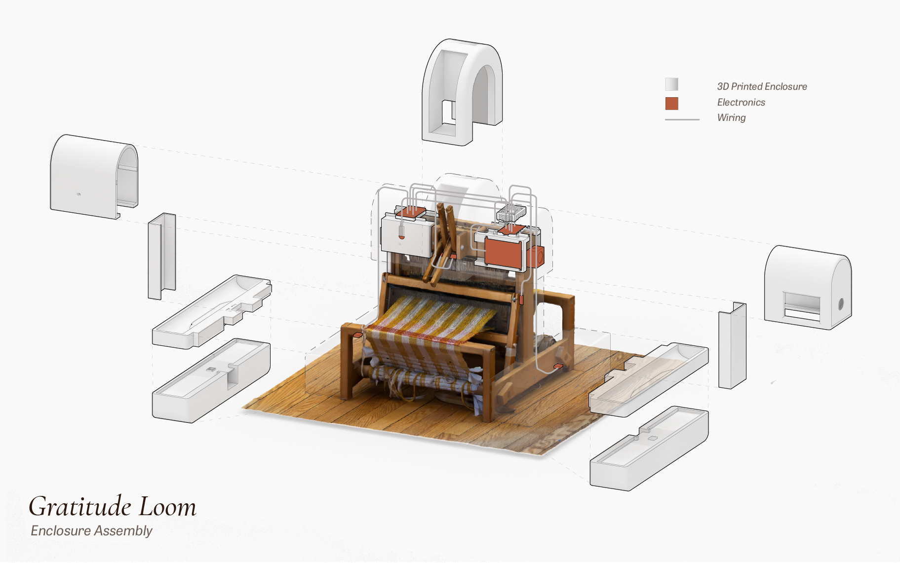
Enclosure Assembly — Pattaraporn (Porpla) Kittisapkajon
Parts to print
- Beater sensor housing — clamps to the loom frame, holds the sensor 2–3mm from the beater's path.
- Beater magnet mount — small clip that holds the magnet on the beater bar itself.
- Shuttle dock pair (L and R) — sit at the ends of the breast beam. Sensor faces upward so the shuttle, with its embedded magnet, passes overhead.
- Shaft lever sensors (×4) — small brackets that mount to the lever housing. One per shaft.
- Magnet inserts (×7) — tiny press-fit holders for the 6mm magnets, so they sit flush against each moving part.
- Pi enclosure — open-top case that mounts to the back of the loom with the divider board accessible. Print in PLA at 0.2mm layer height, 20% infill. No supports needed if oriented correctly.
Assembly order
- Mount the screen, microphone, Raspberry Pi, sensors, and speaker enclosure onto the loom frame using custom-fitted 3D-printed enclosures designed to securely hold onto the structure without modifying the original loom.
- Connect all sensor cables to the breadboard, then connect the breadboard wiring to the Raspberry Pi’s GPIO header.
- Plug in the speaker, screen, and USB microphone, then power on the Raspberry Pi. Final Check
Boot the Pi, SSH into the system, and run python main.py.
Weave a few picks slowly. The terminal log should register activity from each sensor as the loom moves.
That’s it.
The loom is listening.
CODE
File: CODE
3D Printed Parts
File: 3D Files
Notes for makers
If you build this on a different loom, the sensor count and positions can scale. The architecture doesn't care about the number of shafts — it cares about the rhythm of contact. One sensor on the beater of any loom gets you most of the way to a working version.
You can swap the voice config and the prompt. The pattern matrix is also editable — it's a YAML file. The choice of what the loom says, and to whom, is the part of this you should make your own.