Digital bodies
Lecture
Throughout history, the human body has been the canvas for the creation of masterpieces. Today, designers have evolved over time, and so have their tools. That is why, in this phase, we will explore how we can use tools capable of scanning, rendering, and modifying the human figure. In order to develop new ways of creating and responding to needs.

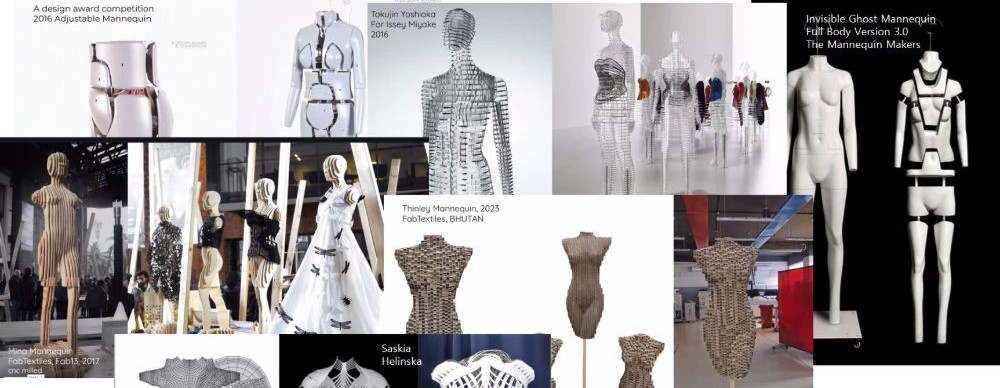
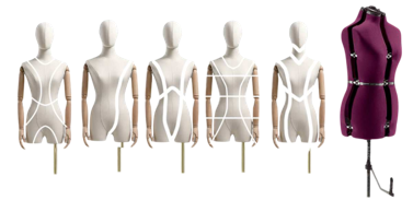
I began with a simple brainstorm. At first, I imagined sculptural figures, but my industrial side kept pulling me toward something functional and adaptable. Then, during the lecture, Anastasia shared ideas along the same lines, and that gave me confidence: I wanted to make mine mannequin adjustable. Especially since I want my final project to be a costume for myself, so a mannequin could be ideal.
Process and workflow
1. Fieldwork
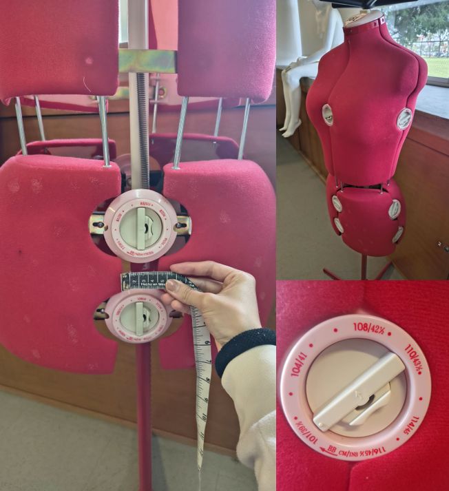
I watched videos to see how one worked: its standard measurements, how far it could expand at the waist, hips, and bust. Still, the questions lingered.
2. Modeling
First Model
-
I downloaded an STL model of the human body.
-
I imported it into Rhino and used the Mesh to NURBS tool.
-
I deleted the mesh and kept the surface.
-
I added a division for my mannequin.
-
Using the Wirecut tool, I can make a cut along the line I drew, and the cut will be solid.
-
Once divided, I exported it as an STL file
-
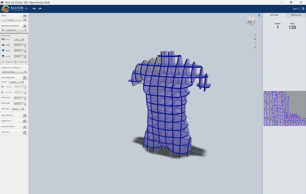
And imported it into Slicer for Fusion
3. Skecthes
I met with one of my advisors Mar and showed my file in Slicer. That moment gave me a clearer idea of the mechanisms my model needed. We bounced ideas back and forth, refining the concept until it started to make real sense.

4. Printing
Excited by the progress, I began modeling the 3D pieces in Rhino. The first design had too many spikes, and we needed a shape that wouldn’t require supports. It evolved into a piece that could be printed as two separate objects.
So we printed the next version:
-
Open Ultimaker Cura.
-
Select filament type (PLA).
-
Set speed to 100 and nozzle temperature to 200 °C.
-
Save G‑code to the micro SD card.
-
Insert it into the ENDER S1 Pro printer.
-
Print.
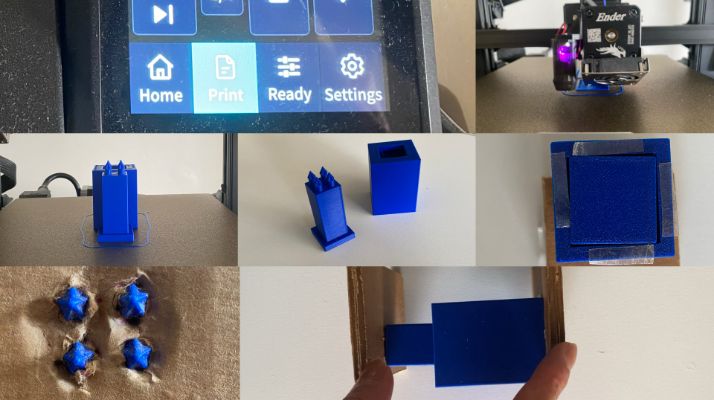
When I saw the printed pieces, I realized it was easier to work with just one spike.
So I printed again, this time using wood filament.
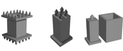
This adjustment made the assembly smoother, and the wood filament gave the piece a warmer, more natural finish.
Settings for PLA filament
- Settings for wood filament
- Speed: 110 mm/s
- Nozzle temperature: 200 °C
Settings for wood filament
- Settings for wood filament -Speed: 60 mm/s
- Nozzle temperature: 220 °C
Scan Practices
Polycam
-
Download Polycam in your phone.
-
Click on "What you want to create". In my case, 3D Object.
-
Prepare your object. Start by ensuring your object is visible from every angle. Lightning is also important, harsh or dark lighting can hurt the sacan quality.
-
Capture your object. You will want to circle around your object in a series of rings, capturing at different heights to ensure you capture all angles.
-
Process your capture.
-
Once captured, all the images that you take will appear as 3d model object.
-
Exported it into a STL file.
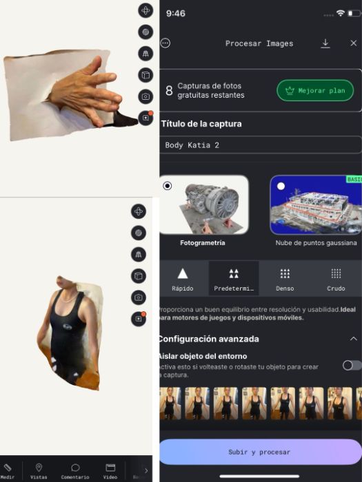
I began with quick scans in Polycam. It worked well for a hand, but despite several tries (arms raised, standing on higher surfaces) we couldn’t capture a full body.
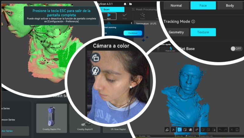
Later, with Creality, I scanned part of my teammate’s face. Unfortunately, when it was my turn, the scan tripled me.
Slicer for Fusion
This digital tool transforms 3D models into flat, two‑dimensional patterns for physical fabrication.
Workflow
- Prepare the STL file.
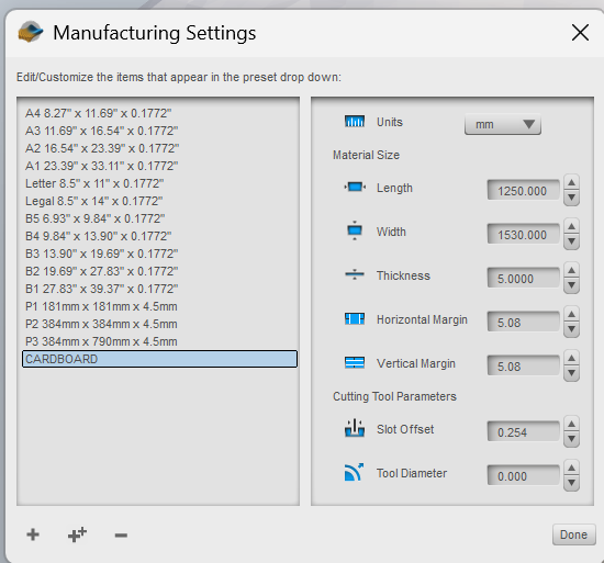
- Go to Import > Manufacturing Settings and add your material dimensions.
- I used cardboard, 5 mm thick.
- Under Units, set the correct measurements for your model.
- I considered only the height: 59.2 cm.
- Select Technique — here you can explore different options and experiment with how the model is divided.
Tips
Be careaful with the measures, as is it of the carboard, the program must use the measure of your laser cut machine. Ex. 90 x 120 cm
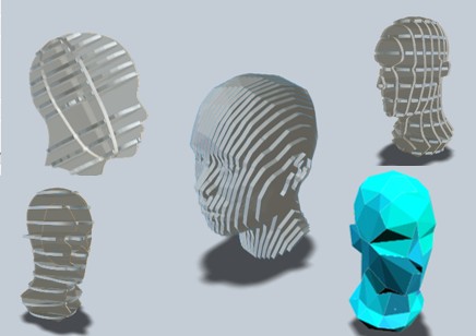
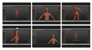
To solve this, I used MakeHuman. I measured myself and entered the exact values in Modeling > Measures, where it even shows how to take each measurement. Then I exported the STL file.
Design Decisions
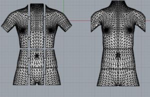
I noticed each division needed adjustments. So I created a new design: cuts across length and width, split into three sections: 12 parts in total.
After dividing, I offset each piece by 1 mm so the slicer in Fusion could recognize the separations, and then exported everything to STL.
Laser Cut
- or embed your own PDF as:
3. Tools
5. Results
Results & documentation
- Don’t forget to document the outcome including:
- Final result
- Photos from different stages
- Videos of movement or interaction, show how a material moves, something was assembled or the interaction
- Include measurements or a reference object to give a sense of scale
- Describe the (material) properties of what you made
- Comparison between attempts, if you did multiple experiments or generated multiple files before fabricating / deploying. You can use a table as shown in week 4
5.1 3D Models
upload DOWNLOADABLE 3d models of your files such as MakeHuman, Final 3d modelled body, 3D Scans, etc. Make sure to make them DOWNLOADABLE.
6. Weekly reflection & critical thinking
I learned how the scanner can capture everything from simple objects to more complex shapes, and that allowed me to create my own 3D model, either with the scanner or with apps that use specific measurements. It was an interesting and challenging project because, as I assembled the pieces, I realized the adjustments needed to achieve a sturdier structure—since the cardboard isn’t very strong—and the measurement calculations complicated the process. I also discovered that modifying the design digitally makes it easier to find solutions, and that while inexpensive materials are useful for rapid prototyping, they aren’t always the best option in the long run. This experience helped me understand basic construction methods and reflect on the impact of materials—both environmentally and practically—as I considered how I could use an adjustable mannequin to test and adapt my designs to different body types. It was very helpful in learning simple construction methods for rapid prototyping and in understanding body representations.
NuEval — final step
Go to NuEval and fill in the checklist, when not complete notify your instructor.
7. Fabrication files & References
-
File: 3d modelling of mannequin ↩
-
File: Laser cut sheets ↩
-
Reference: Author; Title; Source; year ↩