Soft robotics
What if we could control inflatable structures through text?
This week, I explored how silicone, fabric, stitching, and air can turn flat materials into moving forms. I tested different ways of joining materials, made nylon prototypes, and connected these physical experiments to a longer-term question: could text become an interface for designing inflatable structures?
1. Objective
My aim was to learn through making: explore 3D-printed molds, compare sewn and bonded silicone assemblies, and test how a hand-drawn pattern behaves when made in nylon. Alongside these experiments, I began connecting digital fabrication tools to my interest in text-to-inflation for my final project.
2. Research and inspiration
Learning from Porpla
Talking with Pattaraporn (Porpla) Kittisapkajon, a Fabricademy alumna, sparked my curiosity about combining silicone and fabric. Her soft robotics documentation became a reference for my own material experiments.
Read Porpla’s Week 08 documentation.
Pneuhaus: building with air
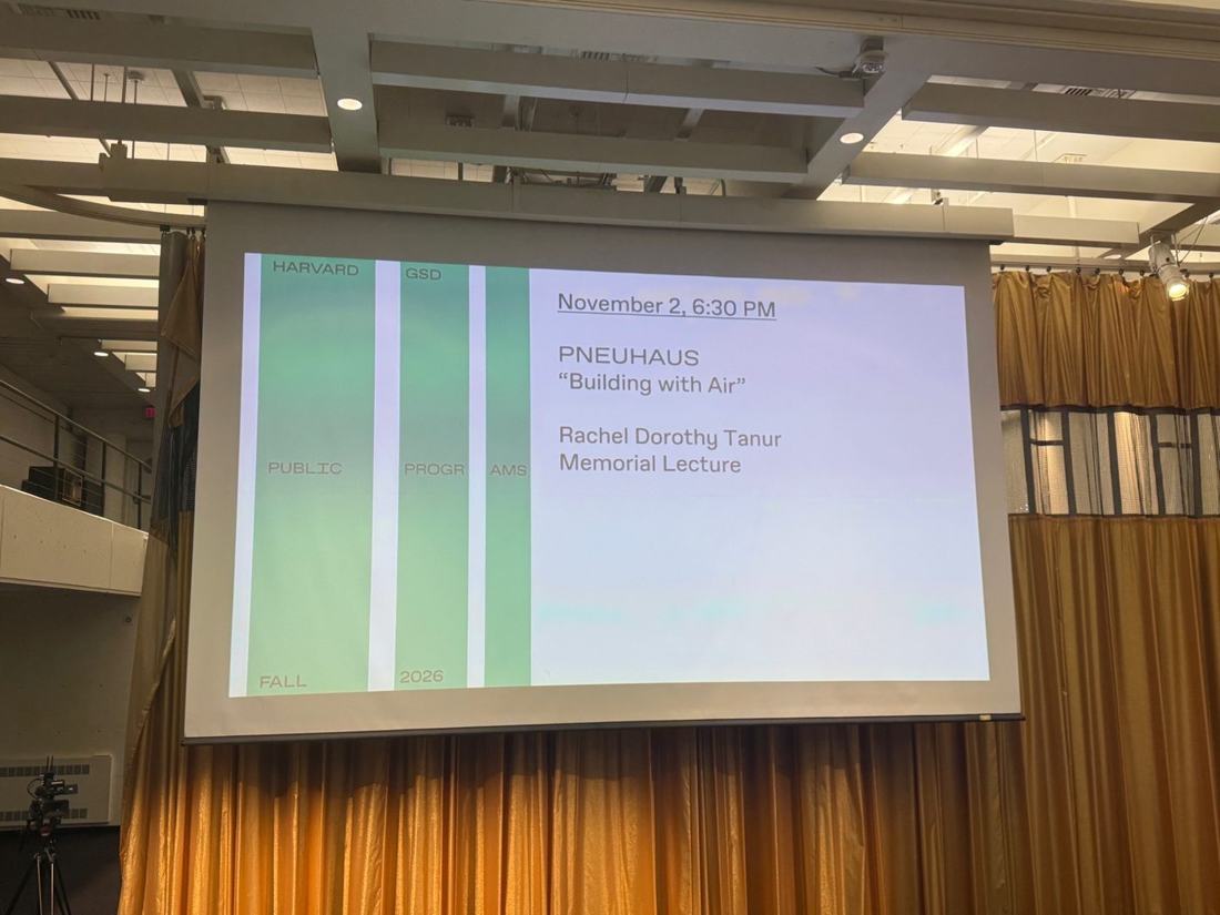
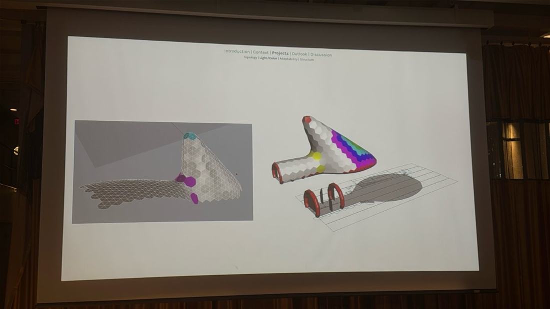
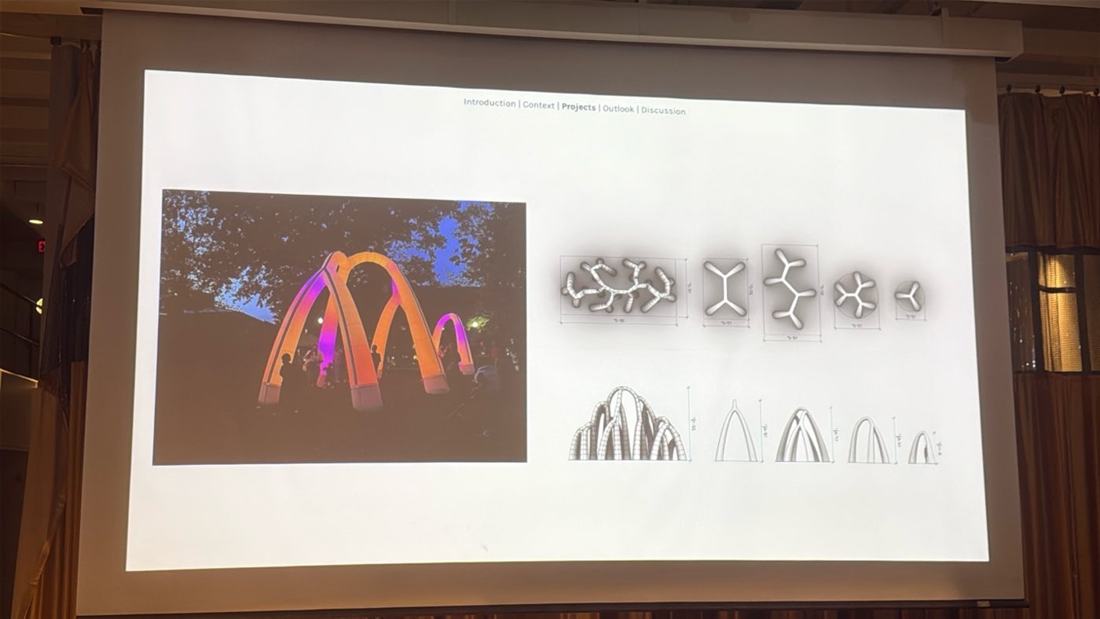
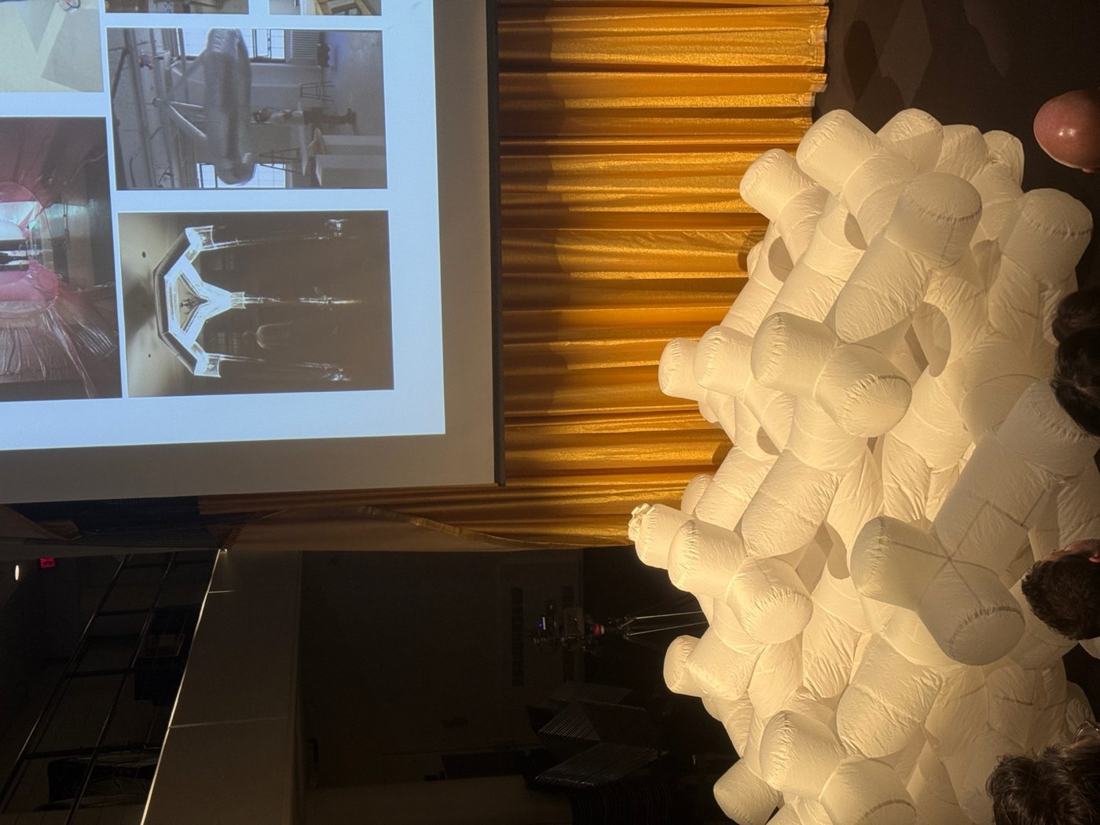
I also attended a Pneuhaus lecture at Harvard Graduate School of Design. Seeing their approach to inflatable structures helped me think about air as part of a fabrication process, from small material tests to spatial assemblies.
Neil Gershenfeld and collaborators: from language to fabrication
Neil’s teaching encouraged me to ask how we might fabricate almost anything using air. A direct research connection is Speech to Reality, by Alexander Htet Kyaw, Miana Smith, Se Hwan Jeon, and Neil Gershenfeld (ACM SCF 2025). It connects natural-language input, a generated 3D mesh, geometric processing, and robotic assembly. The geometry is checked against assembly constraints before the robot builds it. Read the published paper · Author’s project page.
Research demonstration from Alexander Htet Kyaw’s channel; credited to the research team above. Watch on YouTube.
How I connect this to my work: I want to translate a request into textile geometry, fabricable panels, sewn or bonded assemblies, and an inflated form. That is my proposed extension of the prompt-to-fabrication idea; the demonstrated research uses modular robotic assembly. My constraints would include material direction, seam construction, airtightness, pressure, and the difference between a flat cutting pattern and its inflated shape.
Mechanical feedback: MechStyle
A second connection is MechStyle (ACM SCF 2025), by Faraz Faruqi, Amira Abdel-Rahman, Leandra Tejedor, Martin Nisser, Jiaji Li, Vrushank Phadnis, Varun Jampani, Neil Gershenfeld, Megan Hofmann, and Stefanie Mueller. It feeds finite element analysis (FEA) results back into text-driven stylization, reducing geometric changes in regions experiencing higher stress. Its examples concern solid 3D-printed objects, so applying the idea to an inflatable would require a different material model and loading setup. Read the researchers’ project page and paper.
Video linked from the MechStyle research project. Watch on YouTube.
My research question: could structural feedback guide a text-to-inflation workflow before I cut fabric? For example, a requested shape might need a larger tube radius, different seams, reinforcement, or revised supports. Those changes would need simulation and physical validation rather than visual similarity alone.
A related 2025 workshop paper by Kyaw, Jeon, Smith, and Gershenfeld, Making Physical Objects with Generative AI and Robotic Assembly, evaluates fabrication constraints, time, sustainability, functionality, and accessibility. I can use those five questions to assess my own workflow: can it be made, how long does it take, what material is used, does it perform as intended, and who can use the tools?
3. Materials and tools
- Silicone, fabric, vinyl, nylon, and thread.
- Silicone-based adhesive for bonding material layers.
- A 3D printer for making molds and test pieces.
- A sewing machine for joining fabric and assembling patterns.
- A pressure pump for inflation tests.
- My browser-based Panel & Assembly Studio for exploring geometry and cutting patterns.
4. Process and experiments
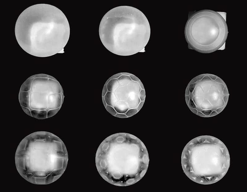
4.1 3D-printed molds
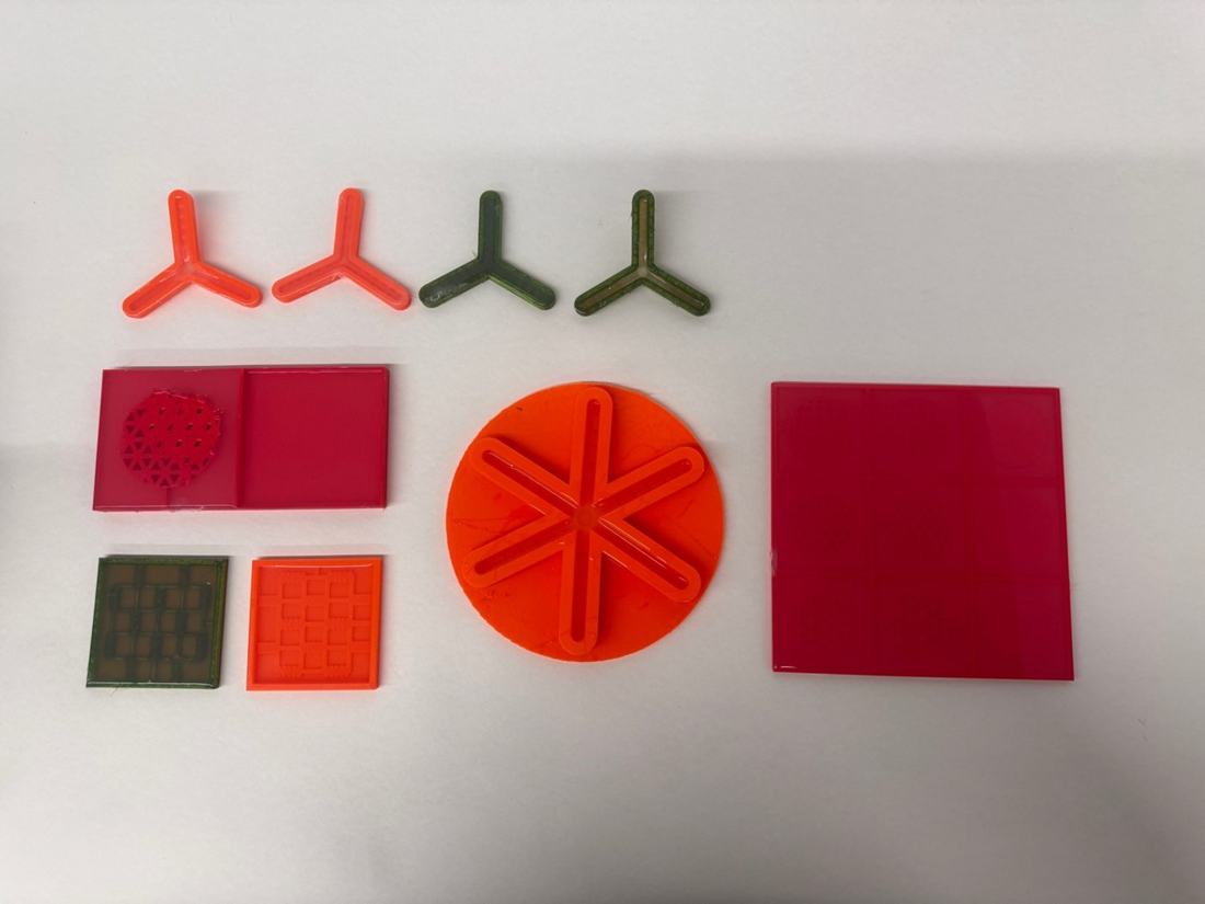
I started by exploring molds made with a 3D printer. The pieces below document this stage of the process.
4.2 Joining silicone and fabric
I explored several assembly techniques: sewing silicone elements together, stitching silicone to vinyl, bonding silicone-coated fabric with silicone-based adhesive, and combining stitching with silicone bonding.
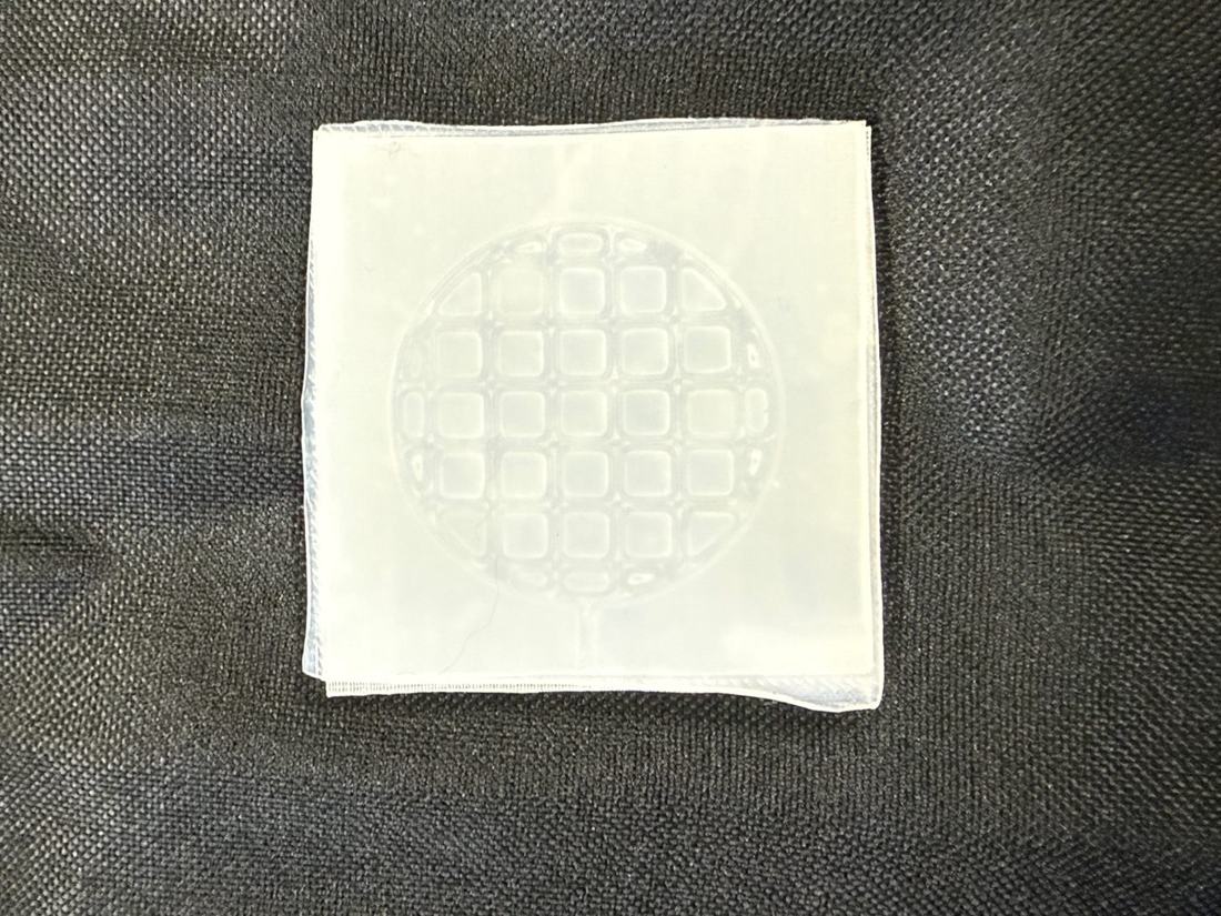
Silicone elements joined by sewing
This test explores stitching as a way to connect silicone elements.
Watch on Vimeo · Video: Prapawit (Pam) Intun.
Silicone and vinyl joined with stitching
I also tested a stitched assembly combining silicone and vinyl.
Watch on Vimeo · Video: Prapawit (Pam) Intun.
Silicone-coated fabric bonded with adhesive
Here I used a silicone-based adhesive to bond silicone-coated fabric.
Watch on Vimeo · Video: Prapawit (Pam) Intun.
Combining sewing and silicone bonding
This inflation test brings sewing and silicone bonding into the same assembly.
Watch on Vimeo · Video: Prapawit (Pam) Intun.
4.3 Thickness, sealing, and inflation
The assembly worked, but my silicone was thicker than Porpla’s reference work. I needed more adhesive and a pressure pump. This made material thickness and the quality of the joins important questions for my next tests.
4.4 Drawing and sewing nylon patterns
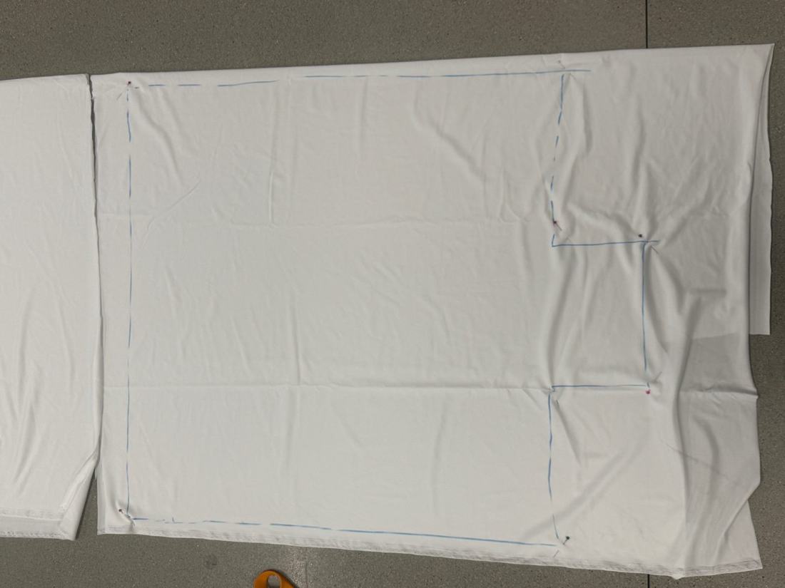
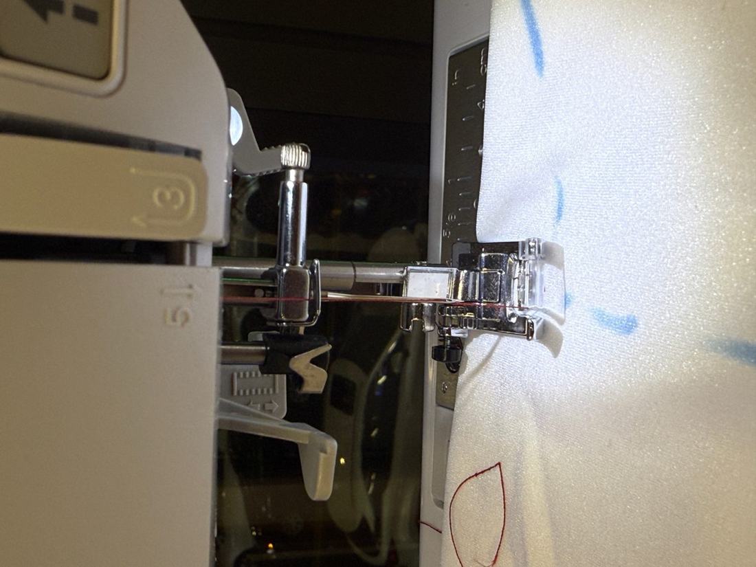
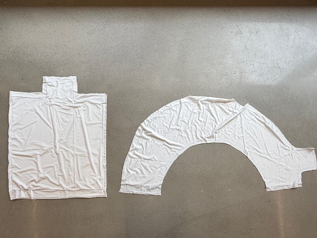
For the nylon experiments, I drew the pattern myself and used sewing to assemble the forms. I enjoyed seeing how a drawing could become a physical object through stitching and inflation.
5. Results: make it blow!
The video below documents my inflation experiment and the movement of the assembled material.
Watch on Vimeo · Video: Prapawit (Pam) Intun.
These tests helped me compare sewing, adhesive bonding, and a combination of both. My next step is to better control thickness and sealing, then connect those material decisions to the digital design workflow.
6. Interactive web app
6.1 Pattern and assembly studio
This browser-based prototype connects my digital geometry work to textile fabrication. It loads my supplied model and can import OBJ, STL, or 3DM files, prepare numbered panels with seam allowances, and export DXF cutting layouts and CSV lists. The assembly view helps identify matching panel edges.
Try changing the panel resolution or dimensions, generating a cut layout, and selecting a panel to inspect its matching seams. For a wider workspace, open the app in a new tab.
Open the interactive studio · View the GitHub repository · Download the standalone HTML
The studio has two connected modes: Pattern & assembly and Structural study. Structural study now uses my supplied AAG mesh, including the current scale and geometry from the pattern editor. It calculates a preliminary nonlinear elastic membrane response to pressure. Text-driven generation and physical inflation control remain future research directions.
6.2 From a mesh to structural behavior
The engineering slide I photographed during the Pneuhaus lecture connects geometric modeling with an analysis visualization. The left image shows a discretized form; the right shows a colored numerical visualization. The photograph does not provide a readable result legend, units, material parameters, or load case, so I cannot identify its plotted quantity or infer structural capacity from its colors.
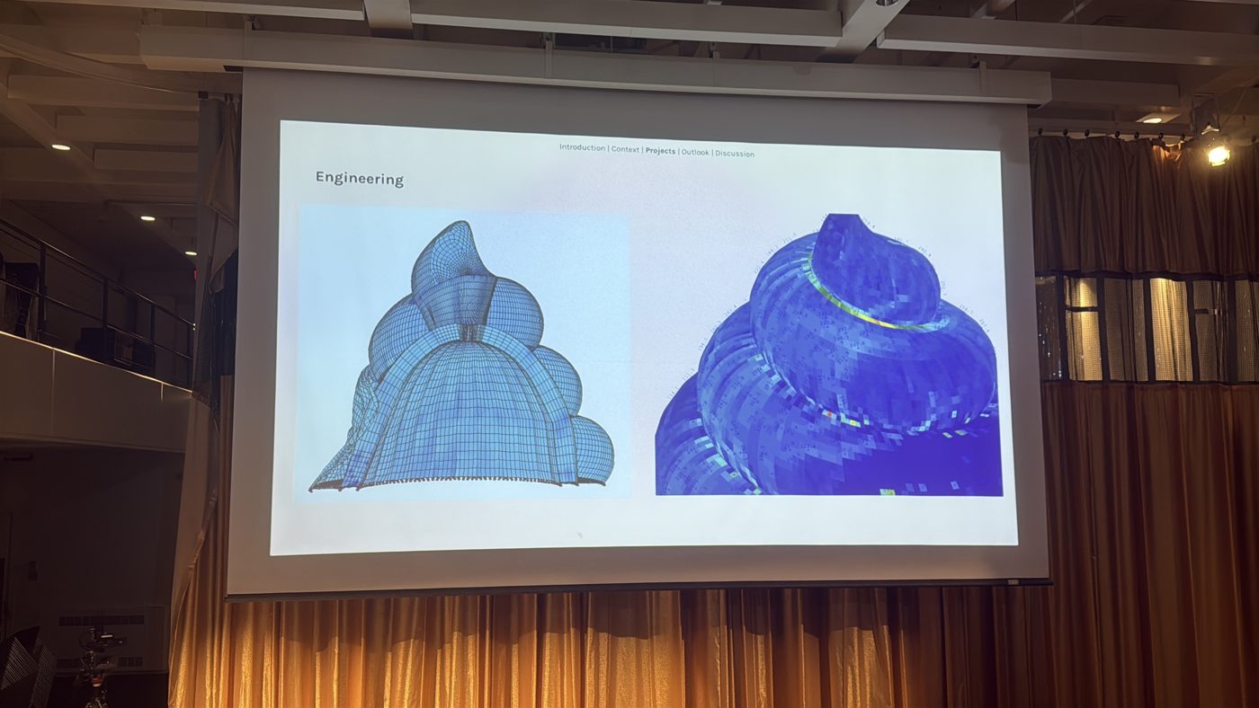
For my work, the question is how internal pressure, fabric direction, thickness, seams, and supports together determine the inflated form and its response to loading. A cutting mesh gives me geometry and assembly information; a structural model also needs material behavior, loads, and boundary conditions.
6.3 Interactive structural study on my model
Select Structural study in the app above, or open the model analysis directly. My supplied AAG model loads automatically. The integrated studio transfers the current pattern mesh and its dimensions, so changes made in Pattern & assembly can be studied on the same geometry. A Use current pattern model button requests a fresh transfer.
The view now shows my actual triangulated geometry. Green dots identify vertices fixed in X, Y, and Z. The initial support assumption clamps the lowest 5% of the model’s Z range; I can change the band or click triangles in support-editing mode. Those supports need to match the real experiment before I interpret the results physically.
The solver applies pressure to the oriented closed mesh and minimizes membrane strain energy minus pressure times enclosed volume. It uses geometrically nonlinear triangular elements and an illustrative isotropic plane-stress St Venant–Kirchhoff material. The optional tension-field relaxation removes compressive membrane stress in slack/wrinkled directions without resolving individual wrinkle shapes. Background references: constant-strain triangles, University of Alberta, and Pipkin’s relaxed membrane energy (1986).
After a converged solve, I can inspect:
- Maximum and minimum principal membrane force in N/mm, colored across the mesh.
- Displacement in mm and a separate visual deformation magnification.
- Maximum Green strain in percent.
- Individual F-numbered triangles and their computed values.
- The force residual, solver iterations, fixed vertices, and a downloadable JSON report.
The starting 0.2 kPa pressure, 0.3 mm reference thickness, 100 MPa elastic modulus, and 0.3 Poisson ratio are example inputs, not measured properties of my prototypes. The default dimensions match the pattern studio’s initial 2,500 × 2,500 × 2,300 mm Fit XYZ settings; transferring my current pattern model uses its current dimensions instead.
This analysis treats the supplied three-dimensional mesh as an unstressed reference surface. It does not simulate assembly from flat sewn panels. It also omits woven-fabric anisotropy, seam slip and failure, self-contact, and calibrated silicone behavior. Numerical convergence establishes equilibrium for the stated assumed model; it does not validate the physical object or its load-bearing capacity. Non-converged runs withhold the displacement and force maps. Support and mesh refinement studies are still needed, especially before interpreting local peak values.
I can also open the separate ideal-cylinder/sphere calculator to compare simple pressure–radius–thickness relationships with an analytical reference.
6.4 What I need for a full analysis of my inflatable
A full model would need the following evidence and setup:
| Part of the model | What I would measure or define |
|---|---|
| Geometry | Flat cutting patterns, inflated dimensions, fabric orientation, ports, and reinforcement. |
| Material | Warp/weft tensile response and shear for woven fabric; a calibrated stretch model for silicone, including thickness changes. |
| Connections | Actual stitched or bonded seam construction, strip-test behavior, and any slip or separation. |
| Loads and restraints | Gauge pressure, self-weight, external loading, and how the specimen is supported or anchored. |
| Solution and checks | Nonlinear pressurization, large deformation, mesh refinement, and convergence before interpreting stress or displacement. |
| Validation | Compare predicted shapes and force levels with measured pressure–shape tests and seam behavior. |
NASA’s Smalley, Tinker, and Saxon study (2002) describes nonlinear pressurization before subsequent modal analysis, capturing the stiffening effect of pressure and checking predictions against an inflated-cylinder experiment. It is a useful methodological reference for moving beyond a static geometric preview.
6.5 Toward a feedback loop for text-to-inflation
My proposed workflow is: describe an intention → generate a candidate form → prepare panels → evaluate material and structural behavior → revise → fabricate and test. Speech to Reality provides a precedent for checking fabrication constraints between a prompt and assembly. MechStyle provides a precedent for feeding mechanical results back into generation. My next research step is to adapt those ideas to pressurized textiles and verify them with physical samples.
7. Reflection and next steps
Sewing was one of the most exciting parts of this week. It gave me a direct way to work with a pattern and see it become a volume. The silicone experiments also showed me that thickness and assembly details can change what is needed to make a piece inflate.
My main challenge is to focus my investigation. I have a clearer idea of what I want to understand: how a design intention can move through digital geometry, a fabrication pattern, material assembly, and inflation. I would like to carry this question into my final project.
For the next experiments, I want to compare more controlled samples, improve sealing, and test the relationship between the drawn pattern and the inflated shape.
8. Files, references, and credits
- Interactive studio and source repository.
- Kyaw, Smith, Jeon, and Gershenfeld (2025), Speech to Reality, ACM SCF; project and demonstration.
- Faruqi et al., including Gershenfeld (2025), MechStyle, ACM SCF; paper and demonstration linked on the research page.
- Kyaw, Jeon, Smith, and Gershenfeld (2025), Making Physical Objects with Generative AI and Robotic Assembly, workshop paper.
- University of Alberta, Two Dimensional Solid Elements, triangular finite element formulation.
- Pipkin (1986), The Relaxed Energy Density for Isotropic Elastic Membranes, tension-field methodology.
- University of Illinois, Introductory Solid Mechanics: Pressure Vessels, analytical membrane equations.
-
Smalley, Tinker, and Saxon (2002), Nonlinear Pressurization and Modal Analysis Procedure for Dynamic Modeling of Inflatable Structures, NASA NTRS.
-
Standalone app HTML, including the app’s embedded source-file downloads.
- Porpla’s soft robotics documentation.
- Pneuhaus, “Building with Air,” lecture attended at Harvard Graduate School of Design; photographs above document the presentation and work shown.
- All five embedded experiment videos: Prapawit (Pam) Intun, hosted on Vimeo.
- Process photographs and prototypes: Prapawit (Pam) Intun, except the credited Porpla reference and Pneuhaus work shown in the lecture photographs.
Special thanks
Thank you to Anastasia for understanding my situation and giving me opportunities to learn; to Sherry, Chelsea, and Jack for providing space, suggestions, and support; and to Kate for sharing her sewing-machine expertise.