Digital bodies
From a scanned body to a mask, a planar grammar and a physical prototype.
1. Objective
This week I explored the relationship between the body, identity and fabrication. My starting points were a masquerade mask, Viktoria Modesta's work and the idea of a planar grammar: translating a three-dimensional form into flat parts that can be assembled physically.
I connected body scanning, mask development and digital visualization with a hand-cut 6 mm foam-board prototype. The physical model is a first test of form and assembly, and a way to prepare for a later laser-cut version.
Digital Bodies assignment criteria · NuEval
2. References, research & inspiration
2.1 Masquerade mask
The masquerade mask is my starting point for thinking about how a surface can conceal, transform or extend the identity of a body. I used this reference to explore the face as both a recognizable human form and a space for sculptural intervention.

2.2 Viktoria Modesta and Critical Matter
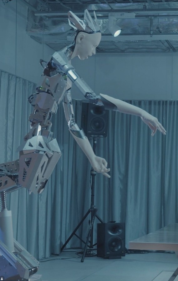
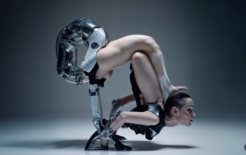
The Viktoria Modesta lecture shared by the MIT Media Lab's Critical Matter Group is a reference for my exploration of bodies, technology and self-expression. I collected the following images alongside this research as visual prompts for the relationship between the body and an external structure.
2.3 Planar grammar
I met Larry last year and met him again this year. We shared our experiences, and I remember his warmth and his wonderful laugh. His article, Plane Delivery: Towards a Physical Grammar for Large-Scale Digital Fabrication, became a starting point for this project.
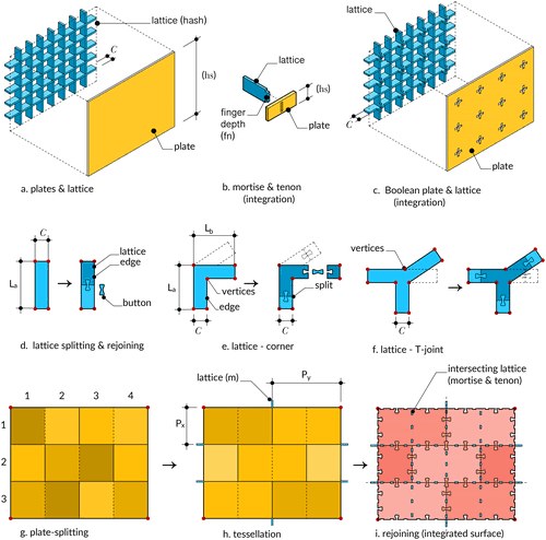
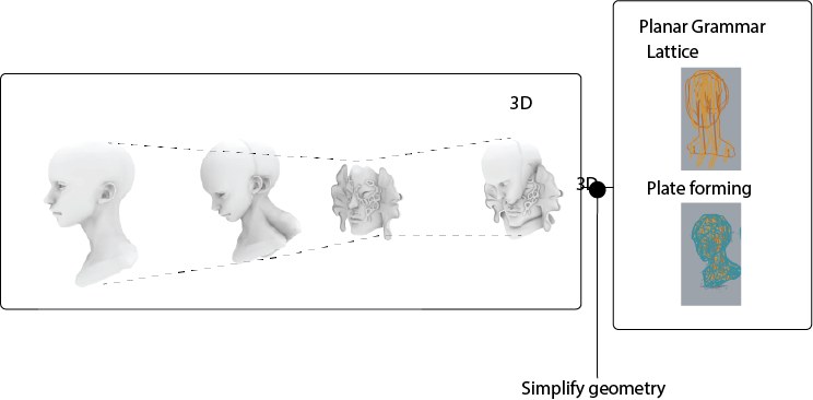
I want to reinterpret planar grammar as a practical method for building different forms. I think of it as an algorithm: start with a three-dimensional shape, divide it into flat parts, define their connections, and assemble those parts into a physical object.
From our conversation, the challenge Larry raised was integration and rejoining. Dividing a form into parts is only one part of the problem; those parts must also reconnect into a coherent whole. In my mask study, this means considering how the internal lattice supports the outer plates, how the joints fit, and how the assembled pieces recover the intended form. The physical prototype tests those relationships.
3. Tools
| Tool or material | Role in this week's work |
|---|---|
| Polycam | Body-scanning route shown in my workflow diagram. |
| Blender | Digital mask and head development shown in my modelling screenshot. |
| Gemini | AI-generated visualization included in my output folder. |
| CAD / DWG | Layout of planar lattice parts in CNC_Lattice_XY.dwg. |
| Foam board, 6 mm | Material for the hand-cut physical prototype. |
| Hand cutting and assembly | First physical test before a machine-cut iteration. |
| Laser cutter | Training and preparation for the next fabrication iteration. |
| Sketchfab | Interactive presentation of the body scan and digital body. |
4. Process and workflow
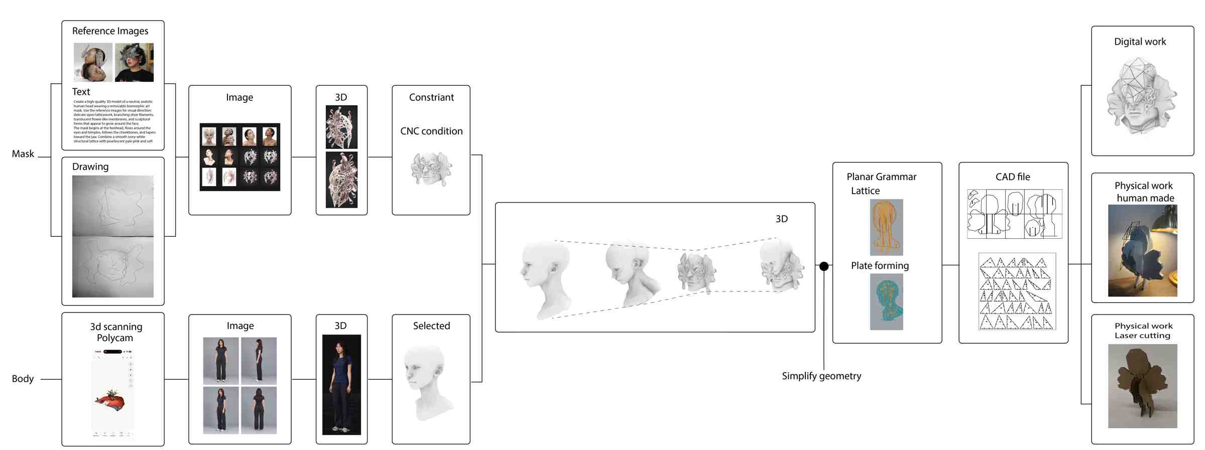
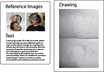
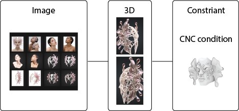
I developed two connected paths. The mask path began with reference images, text and hand drawing. The body path used a 3D scanning workflow to bring the body into a digital environment. My workflow diagram records these routes before they converge in the head and mask study.
4.1 Define the mask
Gather reference images, write a description, and sketch the mask's outline. These inputs guide its shape and visual style.
4.2 Generate mask concepts
Turn the reference images, description and sketches into concept images, then a rough 3D mask. The CNC condition in the diagram means the design must be adjusted so it can actually be fabricated.
4.3 Capture the person
Use 3D scanning or photographs to create a body or head model. Select the portion the mask needs to fit; my diagram shows a head and neck bust.
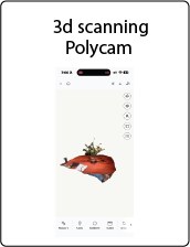
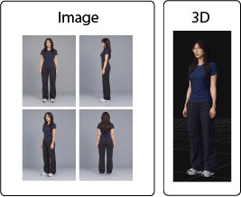
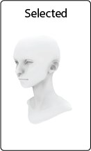
The interactive body scan is available below.
4.4 Combine the two 3D models
Position the mask on the selected head. Check its scale, placement and clearance from the face. This is where the mask-design path and the body-capture path come together.
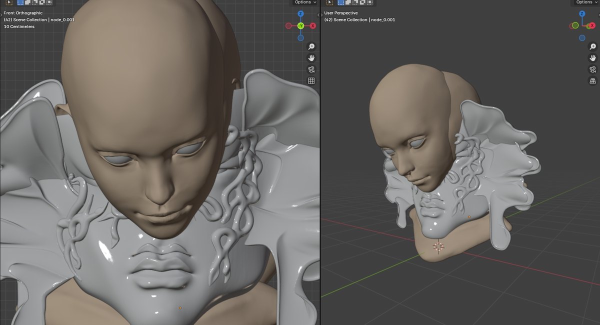
4.5 Simplify the geometry
Reduce the complex sculpted shape into a form that planar pieces can represent. This is the key transition marked Simplify geometry in the workflow: move from expressive surface detail toward a structure that can be divided and assembled.
4.6 Apply planar grammar
Create an internal lattice of intersecting flat pieces and outer plates that follow the mask's surface. Define how the pieces connect. This is the integration and rejoining question in practice: the lattice and surface must work together as an assembly.
4.7 Make the CAD cutting file
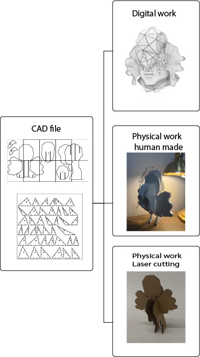
Flatten and label every piece, add its joints or slots, then arrange the pieces on material sheets for cutting. Check the material thickness and the fit of the connections before producing the complete layout.
Open CNC_Lattice_XY.dwg on Google Drive
4.8 Produce and assemble it
Cut the parts, assemble the lattice, attach the outer plates, and compare the physical result with the digital model.
I made the first physical version in 6 mm foam board. Hand cutting gave me a direct way to understand the parts and assembly before preparing a laser-cut version. I also recorded laser-cutting training as part of this week's preparation.
4.9 Test it in 3 mm cardboard
For the cardboard test, make a small mask prototype about 20 cm wide, with five vertical ribs and four horizontal ribs. Where two ribs cross, cut matching slots so they slide together.
For ribs that are 30 mm deep, start with a 15 mm-deep slot in each piece. Slot depth and slot width are different dimensions: the width must fit the actual cardboard thickness. Test a pair of joints first and adjust the fit before cutting the full set.
| Cardboard test parameter | Starting value |
|---|---|
| Sheet thickness | 3 mm cardboard |
| Overall mask width | Approximately 200 mm |
| Vertical ribs | 5 |
| Horizontal ribs | 4 |
| Rib depth at the crossing | 30 mm |
| Slot depth in each mating piece | 15 mm |
| Slot width | Fit to measured sheet thickness; verify with a test joint |
These are the starting dimensions for the cardboard test, separate from the earlier 6 mm foam-board prototype.
5. Results
Physical prototype
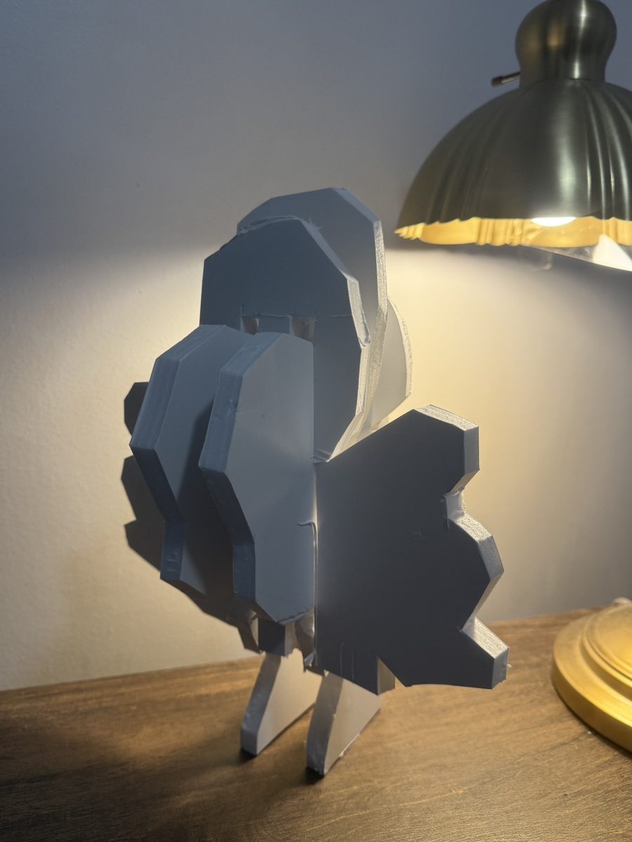
The prototype helped me connect planar grammar to physical work. The updated workflow also shows a laser-cut outcome. The 3 mm cardboard test in Step 9 sets out the dimensions for checking the rib and slot assembly; its joint fit should be verified before the full layout is cut.
Digital visualization
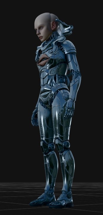

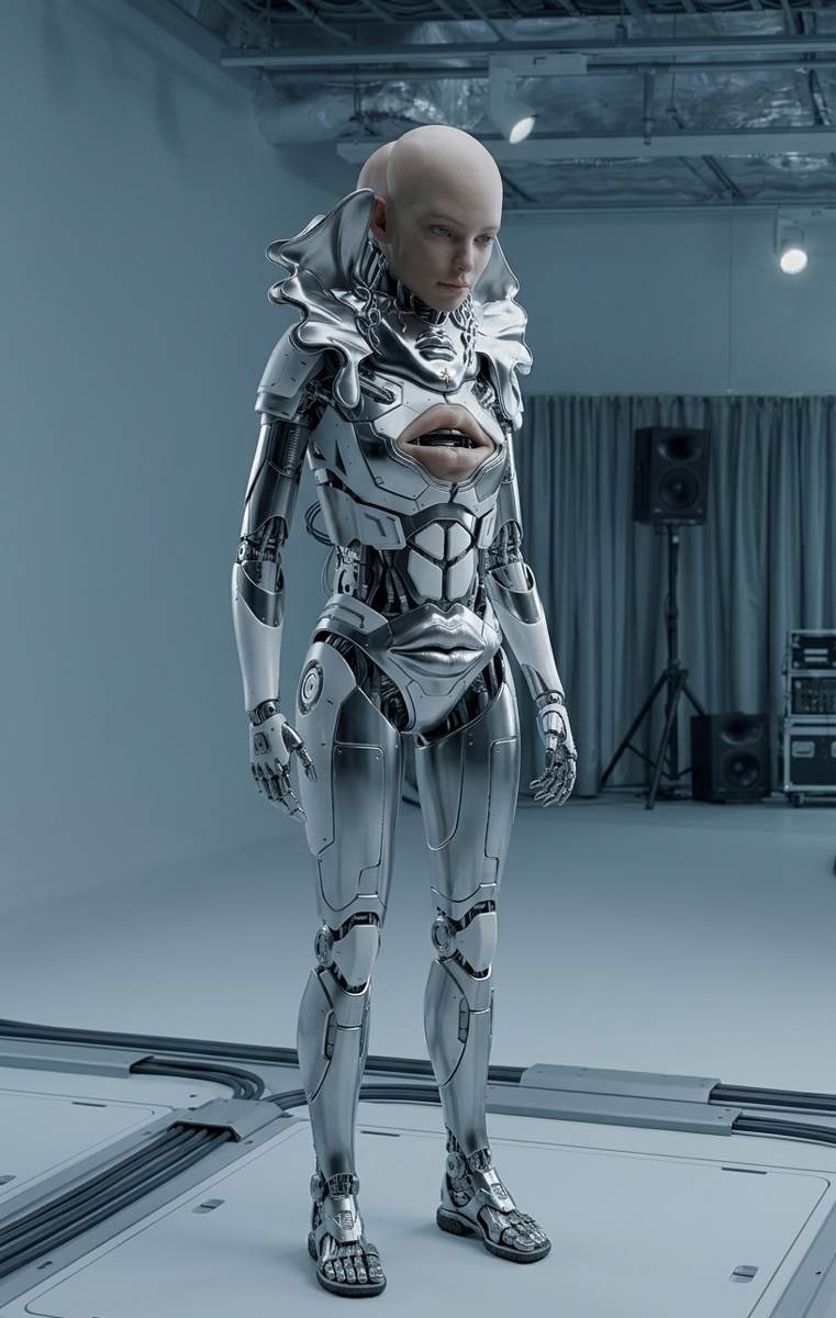
5.1 3D Models
Body 3D scanning
Full body
The mask outcome, simplified geometry and planar grammar model are embedded directly in their process steps above.
6. Weekly reflection & critical thinking
What I learned. Working with a grid helped me connect critical thinking and creative thinking. I began to understand how an expressive body form can be described through repeatable parts and a physical assembly process.
What I would change. I would check material thickness and joints more carefully, and double-check the geometry in the software before cutting. A joint that looks right on screen still has to work with the actual sheet material.
Connection to my final project. This week connected planar grammar with physical work. Hand cutting became a first draft for understanding what a laser-cut version would require. That relationship between a digital body, material constraints and assembly is relevant to my longer-term interest in adaptive skin and fabrication.
Applications and implications. I am interested in how artificial intelligence and physical making can work together in manufacturing. The digital visualizations help me explore possibilities, while the physical prototype provides feedback on what can actually be assembled. Small joint tests before full cutting should also help reduce wasted material.
7. Fabrication files & references
| Resource | File or source |
|---|---|
| Planar lattice cutting layout | CNC_Lattice_XY.dwg / Google Drive |
| Body scan | 3D scanning / Sketchfab |
| Digital body | Digital Bodies / Sketchfab |
| Mask outcome | Digital female head with mask / Sketchfab |
| Simplified geometry | Simplified model / Sketchfab |
| Planar grammar model | Planar grammar / Sketchfab |
| Viktoria Modesta image source | Viktoria Modesta / Instagram |
| Viktoria Modesta lecture | VM Lecture / Critical Matter Group |
| Planar grammar research | Plane Delivery: Towards a Physical Grammar for Large-Scale Digital Fabrication |
| Laser-cutting training | Training video / YouTube |
| Result video | Prapawit Intun / Vimeo |
| Documentation reference linked in my report | Jinger Zeng / Digital Bodies |
Images are organized into inspiration/, workflow/ and results/. The workflow and result images come from my DigitalBodies_PlanarGrammar_CNC archive; reference images are identified in their captions. The DWG file is linked separately because the archive contains images rather than original CAD or mesh files.