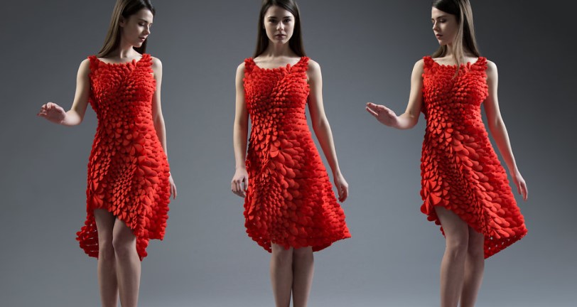
7. Computational Couture#
Inspirational projects#
Weekly task#
-
Develop parametric model in order to design
-
3D Print your parametric design
What i have done ?#
-
Develop parametric model in order to design
-
Learn 3D printer and Took trials on 3d printer
About Grasshopper and Rhinoceros#
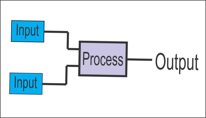
Grasshopper is a combine with Rhinoceros 3D software. Grasshopper installs with Rhino 6 for windows. Basically, Grasshopper is complicated but it is really playful when you understand input and output process. Go here to Download the grasshopper for rhino.
Steps for use Rhino for Grasshopper#
- Grasshopper installation
I installed Rhino for grasshopper from link gave by Fabricademy on my email.
- Set up in Rhino
I started my practice with simple paramatric design which will draw a line between two point in Rhino.

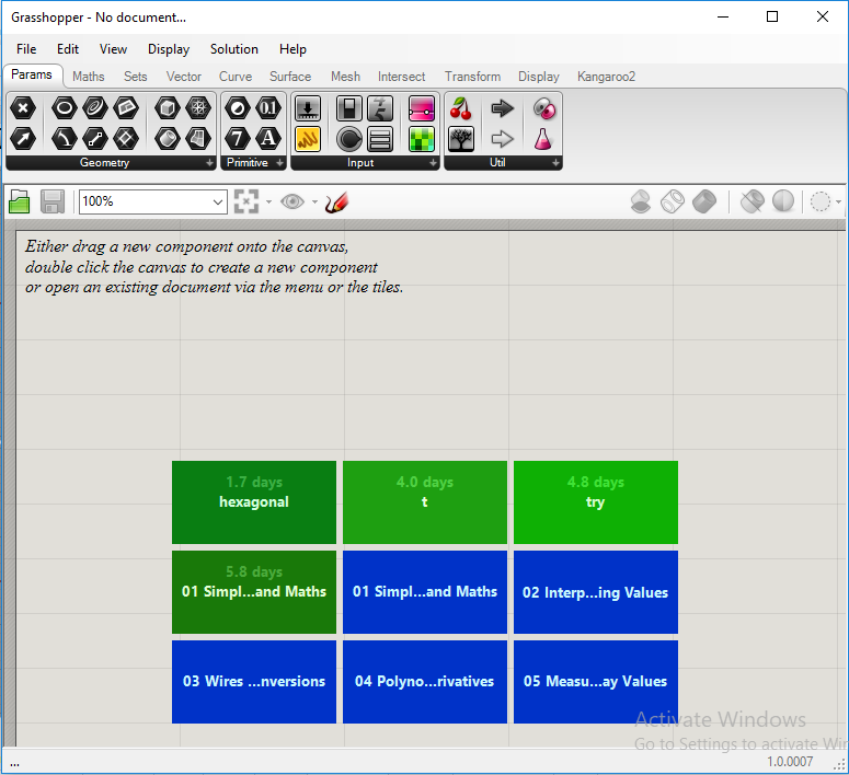
- Open Grasshopper
Once, Grasshopper is installed I typed a command ‘Grasshopper’ to run it.
- Some basics
Some basics which i understand from this link here
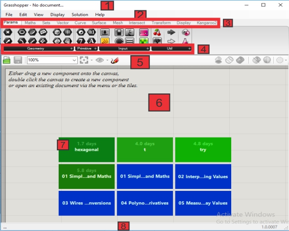
- The title bar- shows the name of opened file.
- The menu bar
- The component liabrary. It involes different kinds of functions.
- It involves different sub-categories of components liabrary.
- Canvas toolbar. It cutains several quick tools to save the file.
- The main canvas....where the magic happens..😍😁
- The recent file or past files.
- The status bar…it gives useful information.
To read, Follow the number which i gave in image…
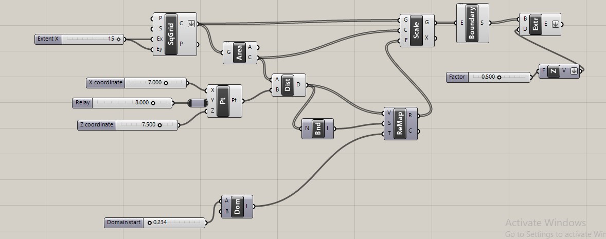
- Let’s go to Grasshopper
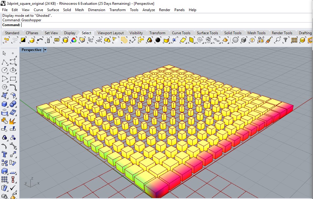
In the step.2 I drew points in Rhino. Now, i turned to Grasshopper I took couple of point parameter component which I found in ‘Params’ tab in the geometry group on the component liabrary. Left click on the icon and then left click somewhere on the canvas.
After this, I found the some another way to took a component on canvas and type ‘whichever component you want’
- Rhino Geometry
Those point component are orange-(indicates a warning). Right click on the first components and select the option ‘Set one point’and then go to Rhino and pick the first point. Repeat the second component and second point.
- Create data flows
I had input point in grasshopper to gererate the line go to component liabrary bar. click on ‘curve’ and then go to ‘primitive’ tool bar click two point ‘line’ component. Here, A and B are the staet and end point of line . Click and hold the left mouse button and drag the mouse away to see a arrow flows my mouse. I moved my mouse over fisrt input line component and release it.
I seen the colour change as line component grey and a line red colour
- Understand input and output process
1st Attempt#
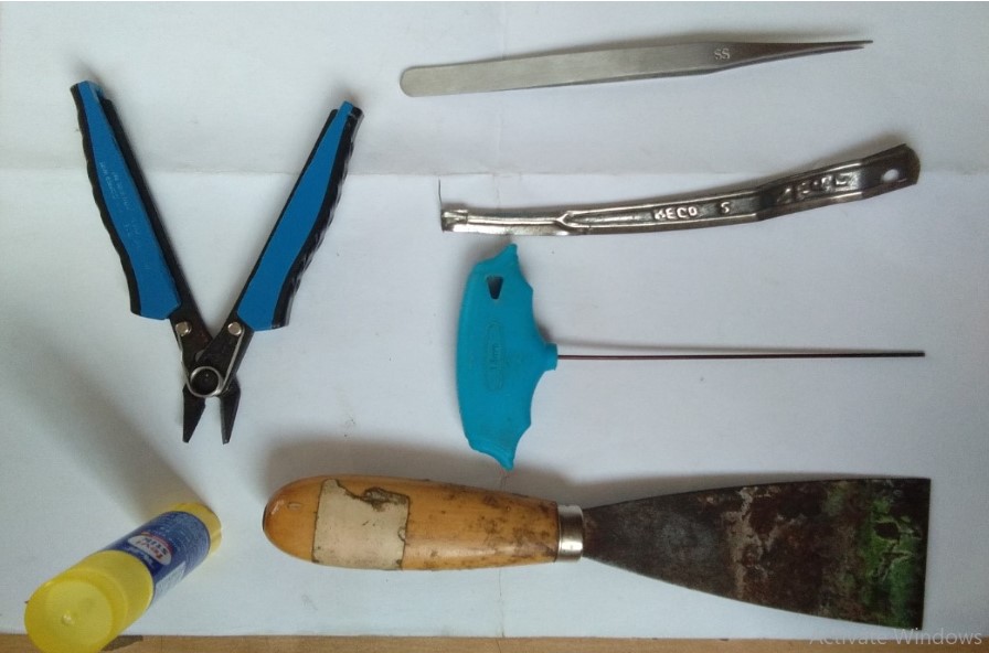
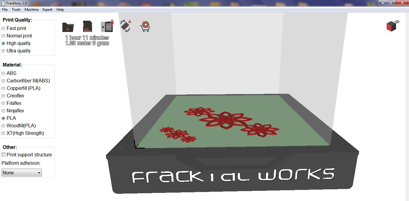
We used these tools when using Julia Printer.
And this is Julia 3d printer.
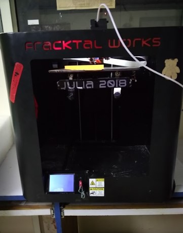
Specification
- Bed size of Julia is 210250260mm
- Filament diameter is 1.75mm
- Printing material - ABS, PLA, carbonfill(ABS), Copperfill(PLA), Creoflex, Woodfill(PLA),etc.
- The printer software supports .stl and .obj files via USB or SD card.
- Nozzle diameter is 0.4mm
- Nozzle temperature for PLA material: 210°C.
- Bed temperature for PLA material: 60°C.
- Rhino and grasshopper program
- Select all Grasshopper program
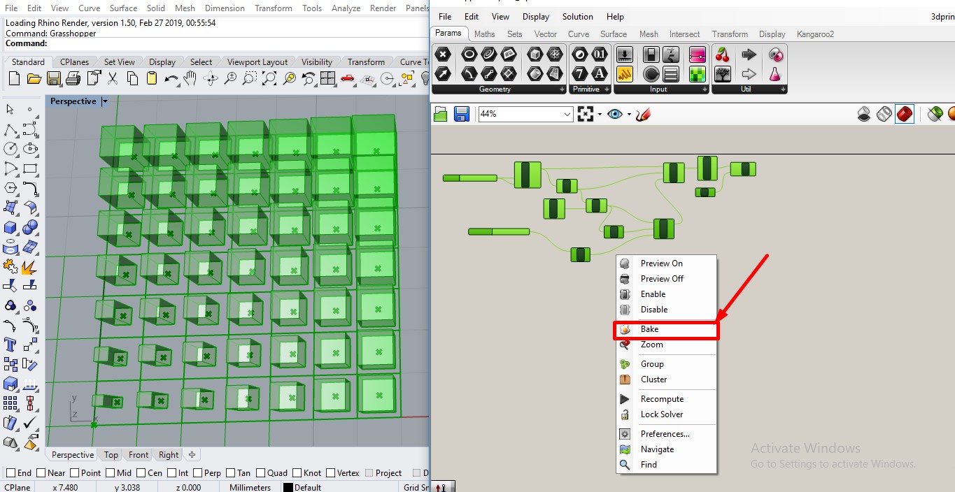
- Then, save rhino file as .stl
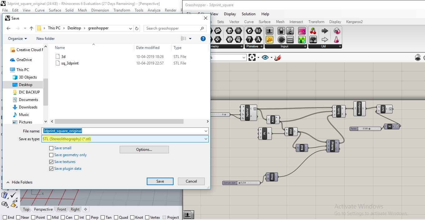
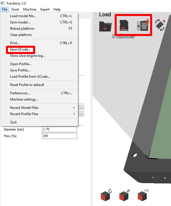
- Load .stl file in fractory software for Julia.

- And save gCode to USB.
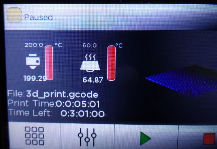
- Set 3d printer on Nozzle temperature 210°C and Bed temperature 60°C for PLA material.
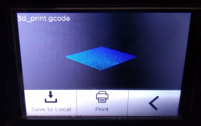
- Open File and start..
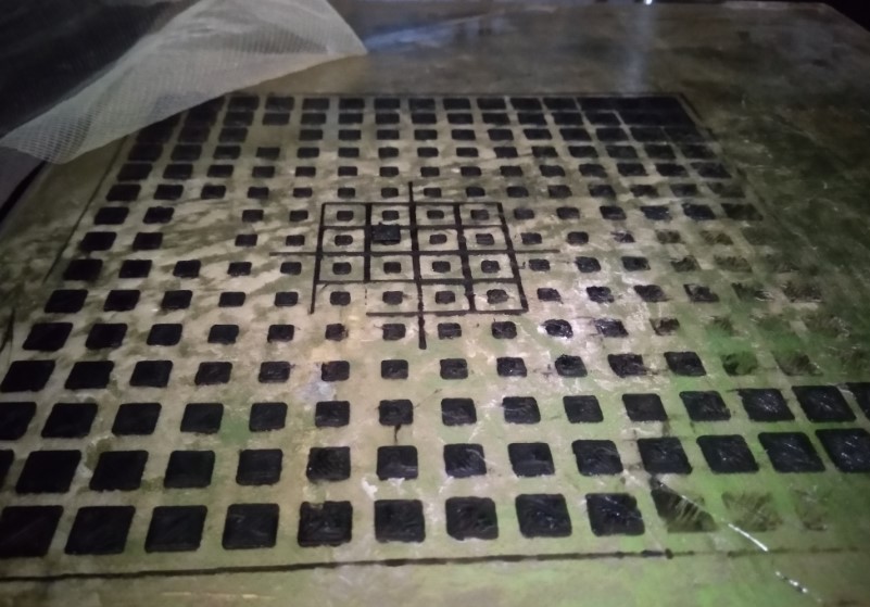
- Pause file after one layer of design on bed
- set fabric with cello tape.
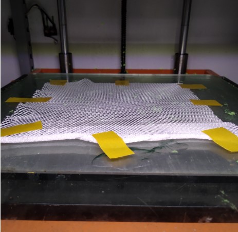
- Set net fabric and start again.
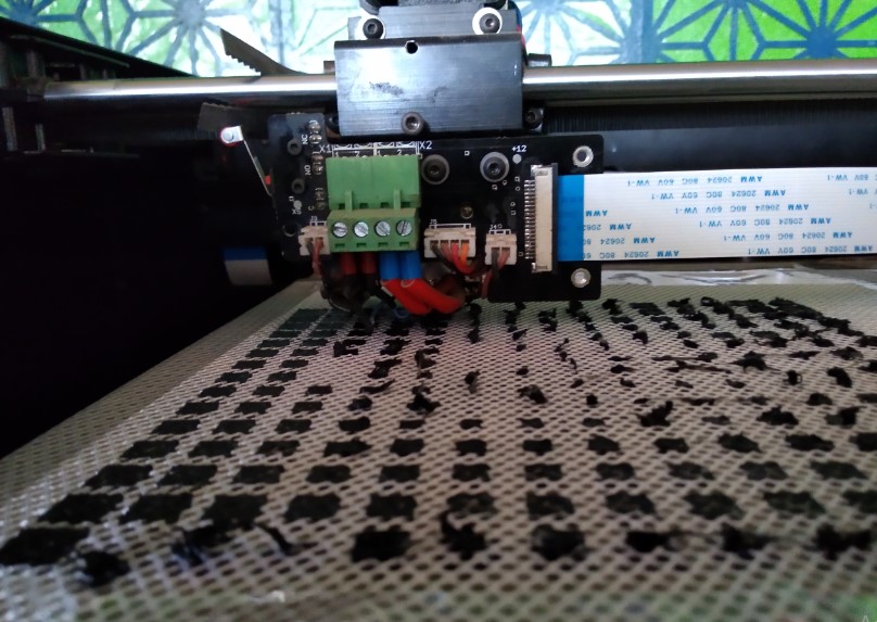
- It’s done.
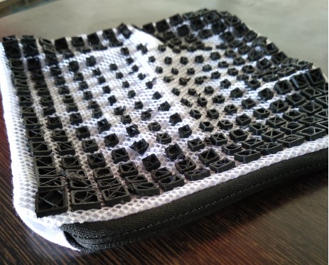
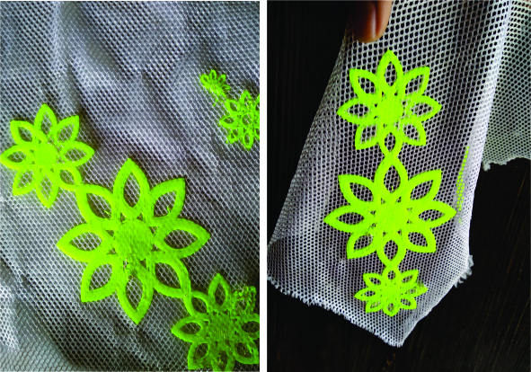
Results#
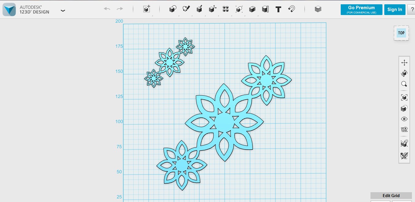
First trial on 123d design software#
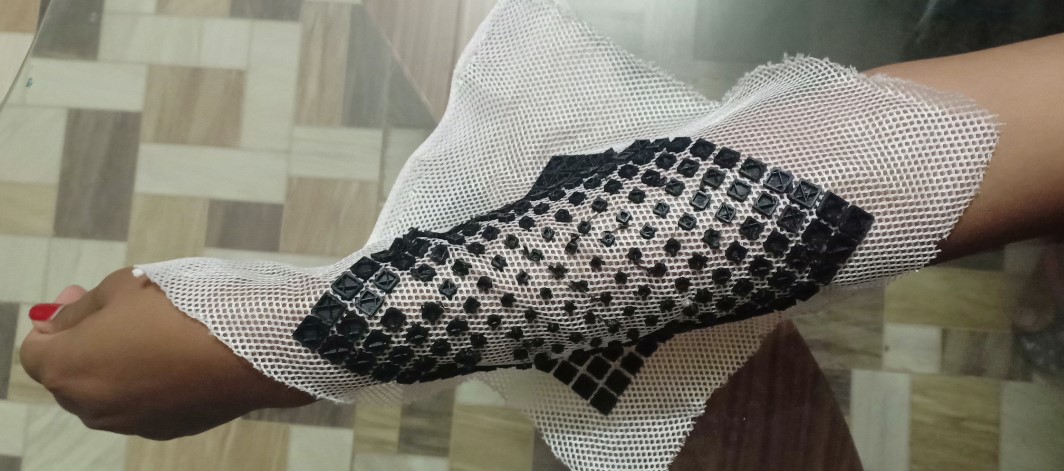
My first experinment on net cotton fabric. I made first design on 123d autodesk software. In vigyan ashram, have two 3d printer, one is Accucraft and another is Julia from Fracktal Works. Personally,I have used both the Accucraft and Julia machines, but I have mostly worked on Julia printer. From setting up to its setup. 3d printer is my favorite machine beacause it has good standardization about maintain origin and and direct follow the gCode. No need to fix the origin and easily controllable. For making gCode we are using Fracktory 2.0 software for main slicing according to the origin and code.
- I made design on 123d autodesk for understanding fabric 3d printing process.
- Save that file as stl and import it Fractory(Julia) software.
- For this 3d printing I use cotton net fabric . Just stick or Clip it on bed of 3d printer. Here I got some step or help to do fabric 3d printing.
Orignal files#
Useful links to learn Grasshopper#
Note
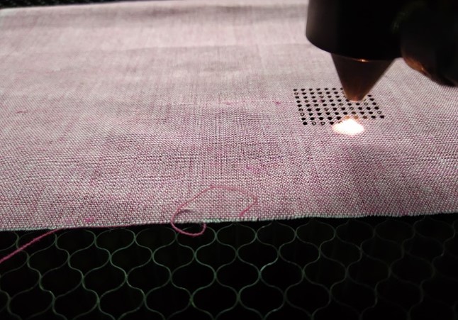
- If you are using cotton fabric cut it wherever you are going to 3d print.I did this with laser cutter which is very useful.
- If you are using flexible fabric please make sure that you clip it ob bed perfectly.
Fabric3d.. Printing from HARSHADA RAUT on Vimeo.

Fabricademy by Harshada raut is licensed under a Creative Commons Attribution 4.0 International License.
Based on a work at https://class.textile-academy.org/.
Permissions beyond the scope of this license may be available at http://vigyanashram.com/.