Another interesting week by Liza stark, This week was about replacing breadboard and arduino with Attiny. Therefore I chose to use Attiny with PIR motion sensor and Led. This week also covers my trial for my final project of using Pulse sensor and vibration motor.
"Whole world in a tiny heart : Attiny"
Nishtha Kaushik


Steps and Processes
Introduction to Microcontrollers and Actuators
Microcontrollers: A Microcontroller is a IC chip that executes programs for controlling other devices or machines. It is a micro (small size as its a Integrated Circuit chip) device which is used for control of other devices and machines thats why it is called 'Microcontroller'.
Actuators: An actuator is a component of a machine that is responsible for moving and controlling a mechanism or system, for example by opening a valve. In simple terms, it is a "mover". An actuator requires a control signal and a source of energy.
Possible components
There are different tools and components you can play with this week.

1. Multimeter an electronic measuring instrument that combines several measurement functions in one unit. A typical multimeter can measure voltage, current, and resistance.
2. An Arduino is an open hardware development board that can be used by tinkerers, hobbyists, and makers to design and build devices that interact with the real world. IDE is the official integrated development environment (IDE) for the Arduino. The Arduino IDE is open source software which is written in Java and will work on a variety of platforms: Windows, Mac, and Linux.
3. Traces will be made either using copper tape or Conductive thread which are ideal for introducing electronics into textiles projects. The thread looks and behaves like conventional sewing thread with the added bonus of being conductive, allowing the thread to be used in the place of wires, with conventional electronics whereas the tape itself is made of thin pure copper so its extremely flexible and can take on nearly any shape. You can easily solder to it, and the tape itself can carry current just like a wire. On the back is an electrically conductive adhesive.
4. Sensors and other components would be like LDR which would be my analog sensor, RGB and vibration motors for this week as I can easily programm and use on arduino but converting them to soft circuit would be a challenge initially.
5.Attiny: The ATtiny85 is a microcontroller in a similar vein to the Arduino, but with much less IO pins, smaller memory and a smaller form factor. In fact, when we talk about the ATtiny85 we refer to the IC itself rather than the board.
Using PIR motion sensor and LED
Here, I started by studying about motion sensor, this sensor is used where one wants the output to be based on motion. Therefore, PIR motion sensor is one of an interesting sensor to use with LED as an output, basically with an idea to have it on Fabrics, where I designed a swatch with motion sensor as an input and LED as an output with Attiny 85.


Below is the pin configuration of ATtiny85 and the datasheet can be found here : Datasheet.
1. Starting by first trying motion sensor and LED on breadboard with Arduino
In this, To program the ATtiny85 we need to first set Arduino Uno in ISP mode.
Connect ATtiny Pin 1 (with the little dot) to Arduino Pin 10.
Connect ATtiny Pin 5 to Arduino Pin 11.
Connect ATtiny Pin 6 to Arduino Pin 12.
Connect ATtiny Pin 7 to Arduino Pin 13.
Connect the ground and 5v from the Arduino to the breadboard.
Connect ATtiny Pin 4 to ground.
Connect ATtiny Pin 8 to 5 volts.
After making conenctions,Connect your Arduino Uno to the PC.
I first uploaded Arduino ISP code, for that
-Open the ArduinoISP sketch from the Examples (“File” ->”Examples” -> “Arduino ISP”).
-Select the board and serial port that correspond to your Arduino board (e.g Arduino Uno).
-Upload the sketch to the Arduino Uno.
and Its done ,Now Arduino is your ISP.
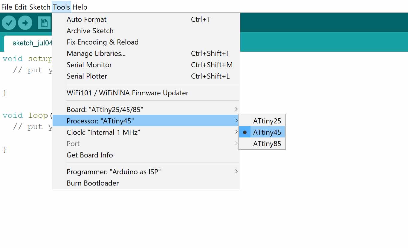
2. By default Arduino IDE doesn't support ATtiny85 so we should add ATtiny boards to Arduino IDE. Open File -> Preferences and in the Additional Boards Manager URLs give this url "https://raw.githubusercontent.com/damellis/attiny/ide-1.6.x-boards-manager/package_damellis_attiny_index.json".
We can then select the board as Attiny45/85 as below
3. To check I ran a blink code first.
Then I uploaded my code for Motion sensor as input and LED as my output.
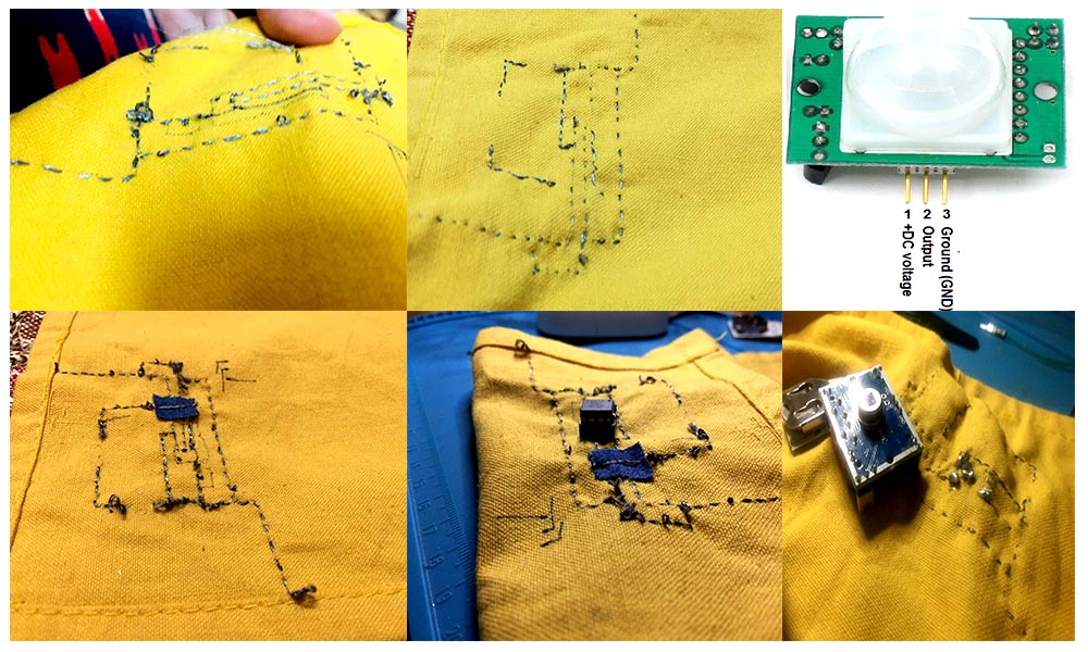
4. Starting Sewing my Swatch:
-Began by drawing details on my swatch and hand sewing with Conductive stainless steel thread.
Actuators: Vibration motor
Below is my swatch where I am using Vibration motor with LDR as an input using copper tape. The connecting wires of vibration motor were small soI have extended them further and secued with hot glue.
Actuators: Flip Dot
Step 1: Created my coil for around 60-70 times
Step 2 :Locking the loop
Step 3:Soldered the ends
Steps 4: Wrapped with thread
Step 5: Sew bead into the loop
Trying Pulse sensor