10. Wearables & E-textiles II
This second class on the topic of wearables and e-textiles provided a more advanced coverage on soft sensors and actuators and programming interactions
Research
To start with this week assignment I searched for bibliography and works and projects of designer, artists and professionals related with Wearables and E-textiles.
Bibliography
-Saliha Ağaç; Merve Balkış (2018). Smart Costume Design With Wearable Electronics
Inspiration

see-thru-me from Peet Sneekes on Vimeo.
Topographie digitale from DataPaulette on Vimeo.
(no)where(now)here : 2 gaze-activated dresses by ying gao from ying gao on Vimeo.
Useful links
- https://www.kobakant.at/DIY/
Assignment
This week, both from the lecture and the tutorials, we continued learning about e-textiles and wearables, following what we started to cover in week 5, making the circuits more complex and increasing the possibilities. In particular we learned what Actuators are, what different types of outputs we can incorporate to our circuit, and how we can control and power them.
For this week we were asked to create samples and swatches using different outputs. Through tutorials, we worked particularly with light (neopixels) and sound (fabric speakers + amplifier circuits and code).
I wanted to design a swatch that included an accelerometer, so I did a lot of experiments with those components.
Complication
This week was a difficult week as we could not get many of the electronic components that were asked for the assignment, since they are not sold in Uruguay. For e-textiles assignment we had made an order abroad with more time, but for this week it was not possible, so we were missing many materials. We could not get the right Mosfet transistors to assemble the driver circuit, nor could we get flexinol, any kind of thermochromatic pigment or ink, we could not buy the 2.5W mono amplifier, nor the DFPlayer-mini.
Despite not getting the right components, I followed the tutorials and tried to do the exercises with the materials I got, but most of the times I could not make the circuits work. The fact that I was working with components that were not exactly the required ones, and doing the tutorials alone, caused me to not even know where the circuits were failing.
Fortunately, Liza's presentation is very complete, full of references to other artists as well as links to tutorials and very clear explanations; Emma's tutorials, just like the e-textile week, were very very good, as she explains with a lot of patience the step by step of making circuits and programming with Arduino.
Process
Power Loads and Driver Circuit
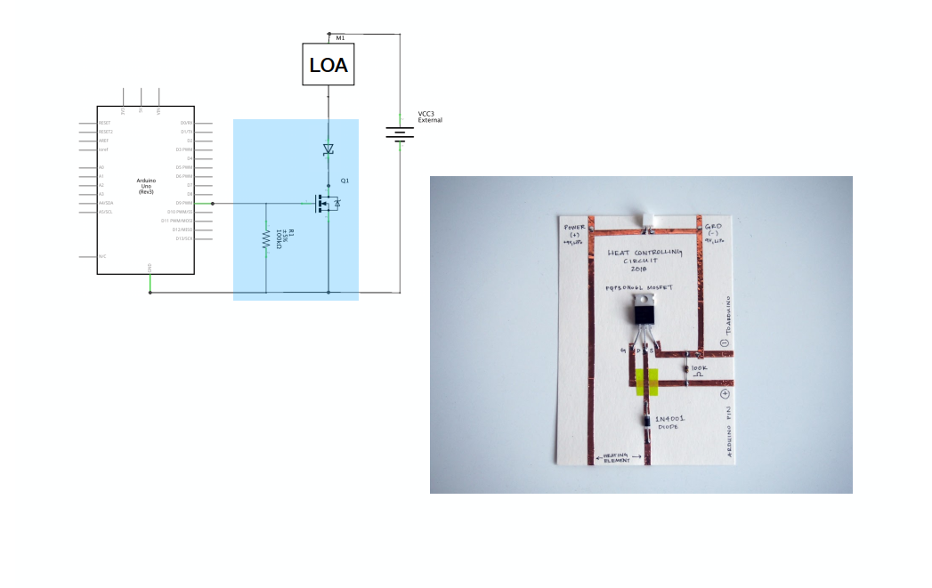
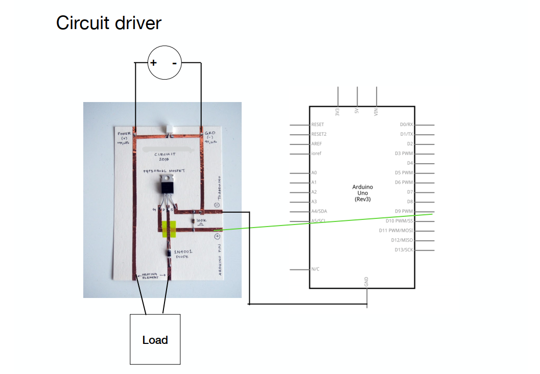
In the Tutorials Emma defined a Power Load as an output that can not be supplied by the Arduino I/O pin (as the maximum current that a IO pin can source is 20mA)
A driver circuit is a circuit that allows us to control a Power Load with low voltage (Arduino) but the Current for the Load in sinked by a different source.
In Weareables Week, we learned how to use transistors as an electrical swithc. A transistor is an active component. Its behaviour changes based on the Voltage applied to one pin (Gate). By applying a small amount of voltage to the gate using the lilypad, current can flow between the drain and the source.
![]()
![]()
![]()
 Emma Pareschi Tutorial Notes
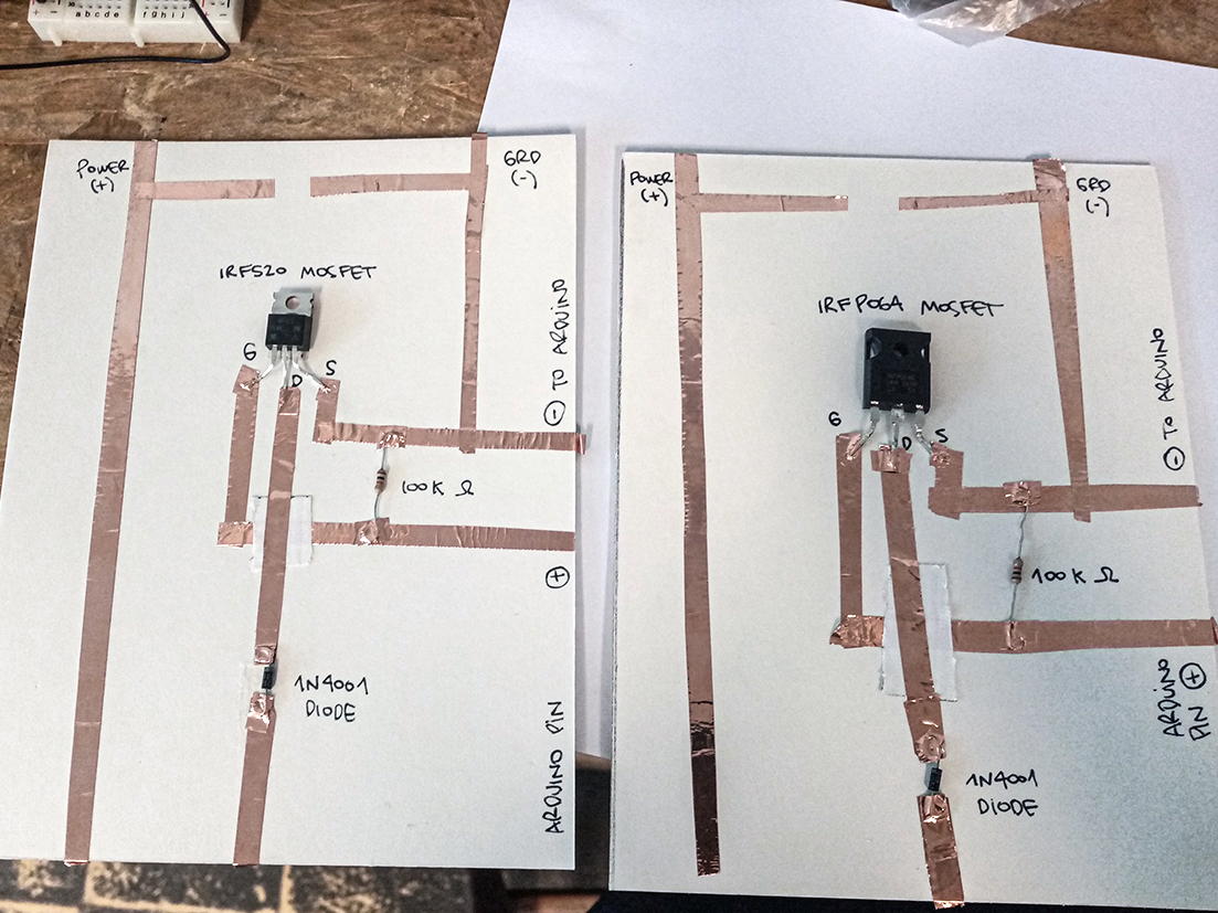
In the tutorial Emma recommended we use a N-channel Mosfet - IRLB8721PbF Transistor , but I wasn´t able to get the same in Uruguay. These are the transistors that I was able to get: IRF520, IRFP064 and a QM3006D.
In the first tutorial, Emma showed me how to check the characteristics in the datasheet.
![]()
I checked each transistor datasheet, and compared the threshhold voltage, as I need a very low threshold voltage max, it has to be less than 2.5V so you can control it directly from a microcontroller running on 3.3V or 5V logic.
I made two driver circuits just like Liza showed, with the two n channel transistors we got.
Tutorials
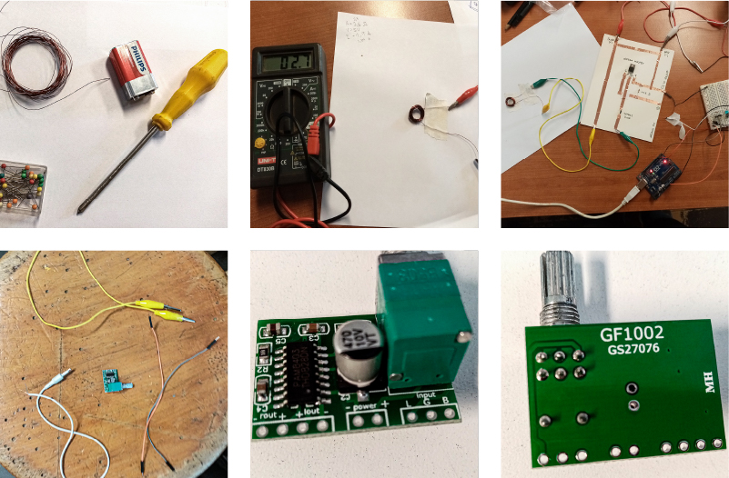
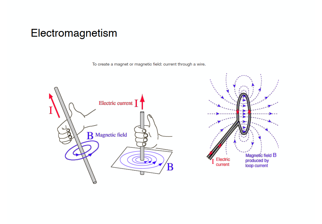
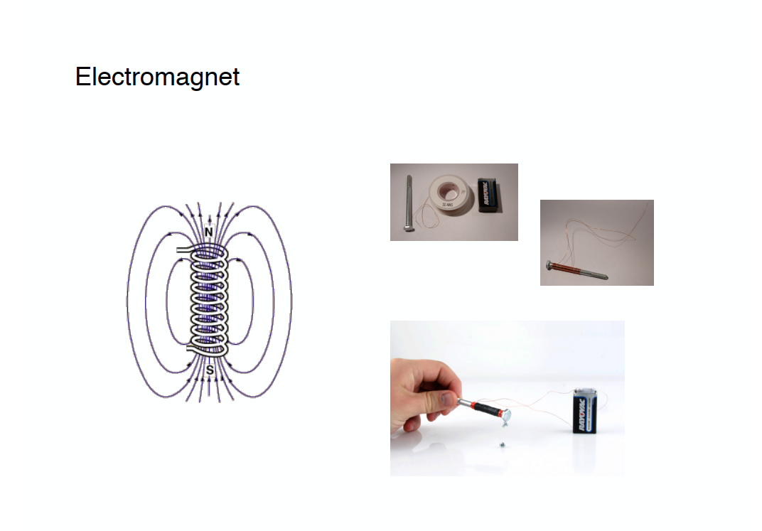
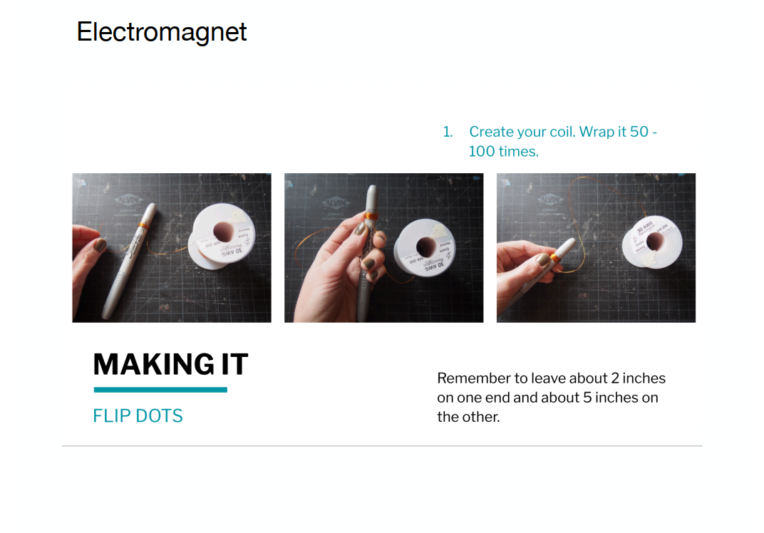
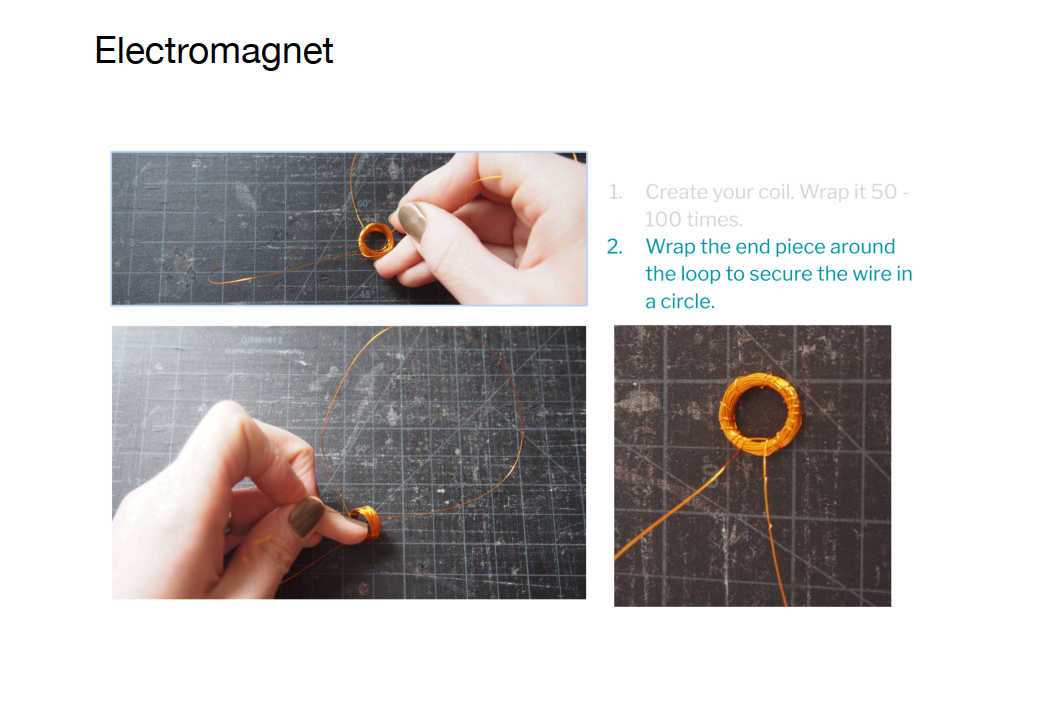
Making an electromagnet
 Emma Pareschi Tutorial Notes
When current flows through the copper wire, a magnetic field is produced around the coil.
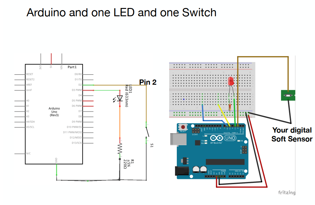
Turning a Led on/off with a switch
Circuit+Scheme
Code
/*Emma Pareschi,
 * this skecth is a modification of the example button!!
 */

int digital_sensor_pin = 2;     //change the pin, where the sensor is connected?
int digital_sensor_value = 0;   //variable in which we save the sensor voltage
int led_pin = 3; //change the pin of the Led

void setup() {
  // put your setup code here, to run once:
  pinMode(digital_sensor_pin, INPUT_PULLUP);  //initialize the sensor pin
  pinMode(led_pin, OUTPUT);   //initialize led pin
  Serial.begin(9600);

}

void loop() {
  digital_sensor_value = digitalRead(digital_sensor_pin); //reas the Voltage at pin sensor

  // check if the pushbutton is pressed.
  if(digital_sensor_value == HIGH){    //If it is NOT pressed

      digitalWrite(led_pin, HIGH);     // turn the LED on
      Serial.println("the led is on");

  } else {                             //If it is pressed

      digitalWrite(led_pin, LOW);    // turn the LED off by making the voltage LOW

  }

}
Adding the mosfet transistor to the circuit, not working :(
Testing neopixeles
Neopixels are RGB LEDs with drivers embedded in the chip; this allows them to be addressable and can be controlled individualy.
![]()
![]()
![]() Emma Pareschi Tutorial Notes
Emma Pareschi Tutorial Notes
Rainbow switch test
Circuit + Scheme
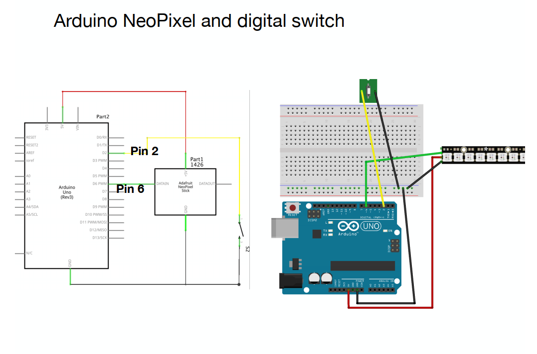 In my case I used two sewable neopixels
Code
#include <Adafruit_NeoPixel.h>
// A basic everyday NeoPixel strip test program.

// NEOPIXEL BEST PRACTICES for most reliable operation:
// - Add 1000 uF CAPACITOR between NeoPixel strip's + and - connections.
// - MINIMIZE WIRING LENGTH between microcontroller board and first pixel.
// - NeoPixel strip's DATA-IN should pass through a 300-500 OHM RESISTOR.
// - AVOID connecting NeoPixels on a LIVE CIRCUIT. If you must, ALWAYS
//   connect GROUND (-) first, then +, then data.
// - When using a 3.3V microcontroller with a 5V-powered NeoPixel strip,
//   a LOGIC-LEVEL CONVERTER on the data line is STRONGLY RECOMMENDED.
// (Skipping these may work OK on your workbench but can fail in the field)

// Which pin on the Arduino is connected to the NeoPixels?
// On a Trinket or Gemma we suggest changing this to 1:
#define LED_PIN    6

// How many NeoPixels are attached to the Arduino?
#define LED_COUNT 2

// Declare our NeoPixel strip object:
Adafruit_NeoPixel strip(LED_COUNT, LED_PIN, NEO_GRB + NEO_KHZ800);
// Argument 1 = Number of pixels in NeoPixel strip
// Argument 2 = Arduino pin number (most are valid)
// Argument 3 = Pixel type flags, add together as needed:
//   NEO_KHZ800  800 KHz bitstream (most NeoPixel products w/WS2812 LEDs)
//   NEO_KHZ400  400 KHz (classic 'v1' (not v2) FLORA pixels, WS2811 drivers)
//   NEO_GRB     Pixels are wired for GRB bitstream (most NeoPixel products)
//   NEO_RGB     Pixels are wired for RGB bitstream (v1 FLORA pixels, not v2)
//   NEO_RGBW    Pixels are wired for RGBW bitstream (NeoPixel RGBW products)

uint32_t off = strip.Color(0, 0, 0);
int num_rainbow = 3;

int sw_pin = 2;
int sw_value = 0;

// Variables will change:
int counter = 0;   // counter for the number of button presses
int sw_status = 0;         // current state of the button
int last_sw_status = 1;     // previous state of the button
int counter_reset = 2;


// setup() function -- runs once at startup --------------------------------

void setup() {

  strip.begin();           // INITIALIZE NeoPixel strip object (REQUIRED)
  strip.show();            // Turn OFF all pixels ASAP
  strip.setBrightness(50); // Set BRIGHTNESS to about 1/5 (max = 255)

  pinMode(sw_pin, INPUT_PULLUP);
  Serial.begin(9600);

}


// loop() function -- runs repeatedly as long as board is on ---------------

void loop() {

   sw_status = digitalRead(sw_pin);

   if (sw_status == 0){
      rainbow(10);             // Flowing rainbow cycle along the whole strip
      strip.fill(off, 0, 10);
      strip.show();  //display the color
      counter = 0;
    }
}

// Rainbow cycle along whole strip. Pass delay time (in ms) between frames.
void rainbow(int wait) {
  // Hue of first pixel runs 5 complete loops through the color wheel.
  // Color wheel has a range of 65536 but it's OK if we roll over, so
  // just count from 0 to 5*65536. Adding 256 to firstPixelHue each time
  // means we'll make 5*65536/256 = 1280 passes through this outer loop:
  for(long firstPixelHue = 0; firstPixelHue < num_rainbow*65536; firstPixelHue += 256) {
    for(int i=0; i<strip.numPixels(); i++) { // For each pixel in strip...
      // Offset pixel hue by an amount to make one full revolution of the
      // color wheel (range of 65536) along the length of the strip
      // (strip.numPixels() steps):
      int pixelHue = firstPixelHue + (i * 65536L / strip.numPixels());
      // strip.ColorHSV() can take 1 or 3 arguments: a hue (0 to 65535) or
      // optionally add saturation and value (brightness) (each 0 to 255).
      // Here we're using just the single-argument hue variant. The result
      // is passed through strip.gamma32() to provide 'truer' colors
      // before assigning to each pixel:
      strip.setPixelColor(i, strip.gamma32(strip.ColorHSV(pixelHue)));
    }
    strip.show(); // Update strip with new contents
    delay(wait);  // Pause for a moment
  }
}
Textile Speakers
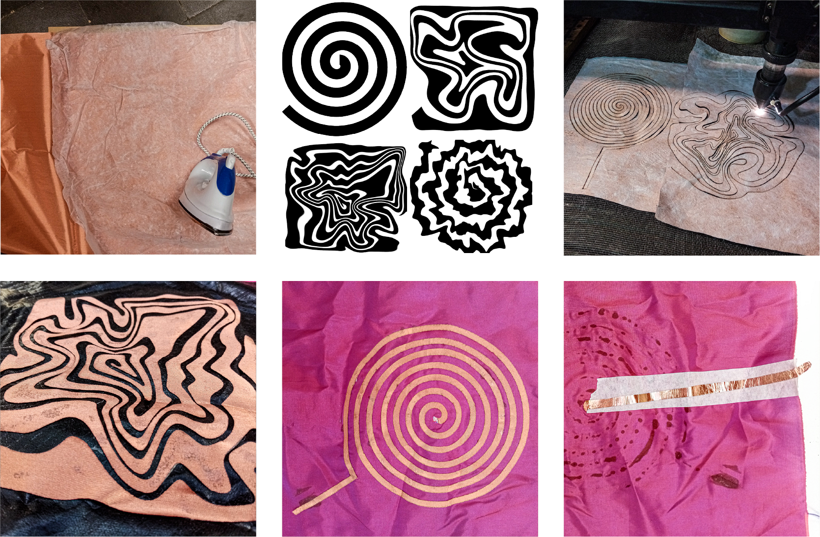
Since I had conductive fabric available, I decided to try the textile speakers. I designed and laser cut various shapes of spirals, in copper conductive fabric with interlining, which I then glued onto different types of fabric: taffeta, lycra, and synthetic leather.
The values I use for laser cutting are: Power: 15% Speed: 2000 mm/s
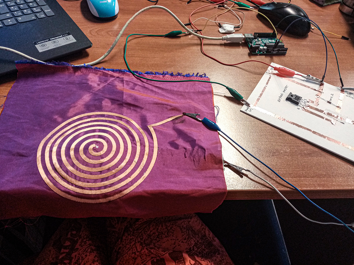
In order to test the speakers, I tried to make an amplifier, however I did not find in the market the same component that Liza uses in her tutorial, Adafruit Mono 2.5W Class D Audio Amplifier - PAM8302. The closest thing I found was a PAM8403 - GF1002 3W Stereo Audio Amplifier Module. I tried to assemble it with alligator cables and an audio cable, but I did not succeed.
I also tried to test the sound by assembling the circuit with the transistor and using direct arduino, however I did not succeed either. Finally, with a protoboard, I assembled a circuit with the speaker and the arduino, without the transistor, and then I could make it work! It was a relief, since all the tests were working badly. I had to use many magnets together, and place the speaker on a can, but I did it! The code I used was the one Emma showed us

Accelerometer
As mentioned above, the objective of this week was to further explore soft sensors, actuators and programming interactions.
Luckily, I was able to get a FLORA Accelerometer/Compass Sensor - LSM303, as well as a LilyPad Arduino USB board, controlled by an ATmega32U4.
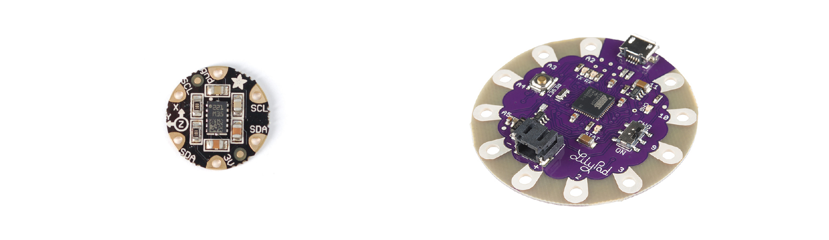
In Adafruit site I found information on how the sensor works, and how the basic connections are made. Inside LSM303 there are two sensors, a 3-axis accelerometer, which can tell you which direction is down towards the Earth (by measuring gravity) or how fast the board is accelerating in 3D space. The other is a magnetometer that can sense where the strongest magnetic force is coming from, generally used to detect magnetic north.
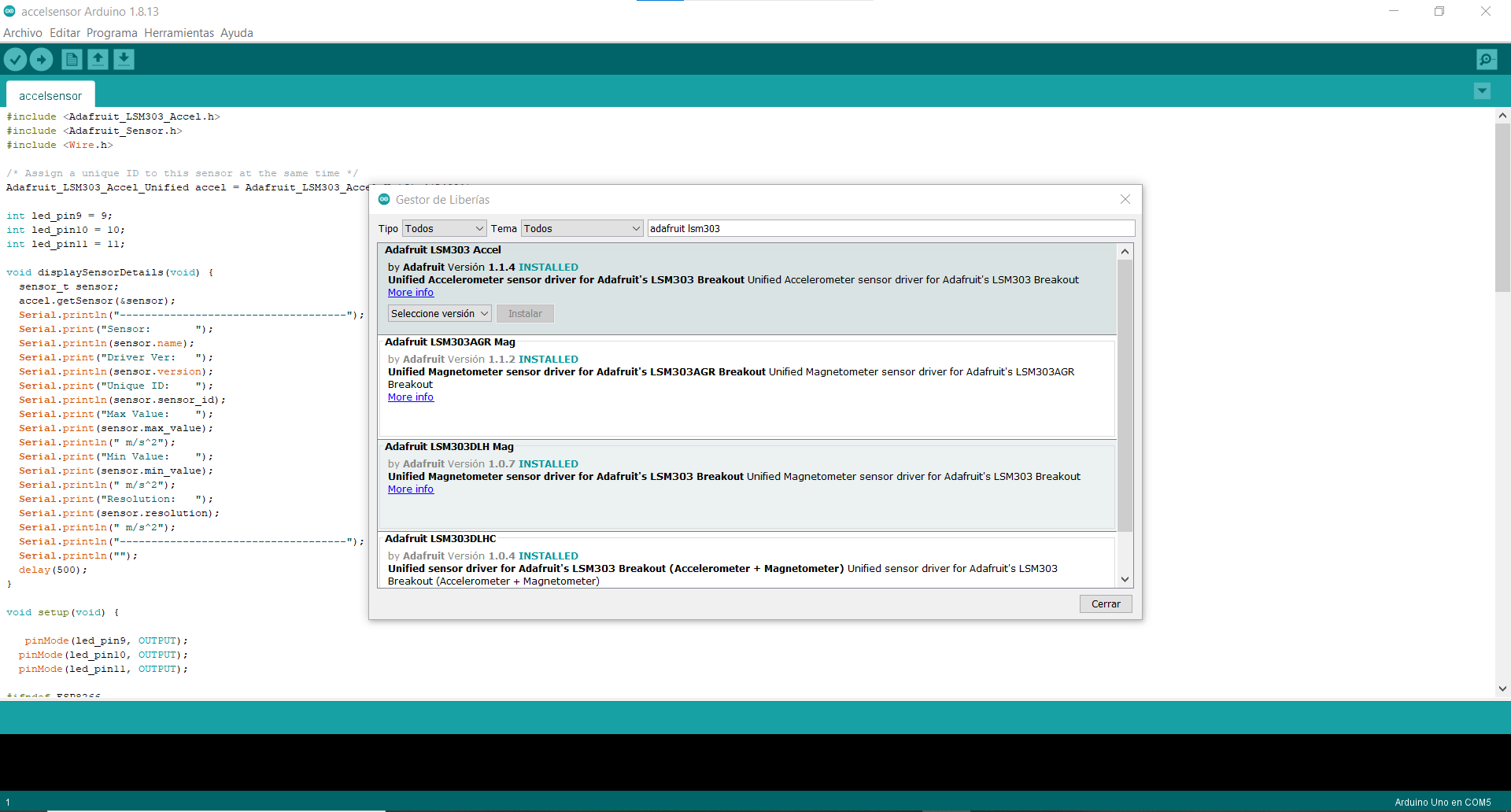
First I tried simply putting the circuit together on a protoboard, and started experimenting with the code, installing the Arduino Adafruit_LSM303 library and testing an example of it.
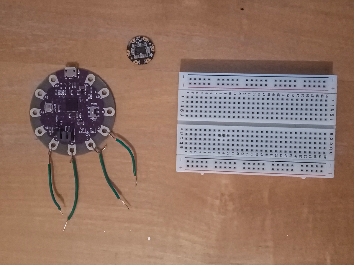
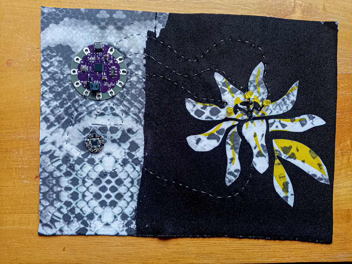
Once I understood the basic connections, I tried assembling a textile swatch, with the microcontroller, the sensor, and three LEDs connected to three different pins of the Lilypad.
Circuit
Schematic
Process
Code
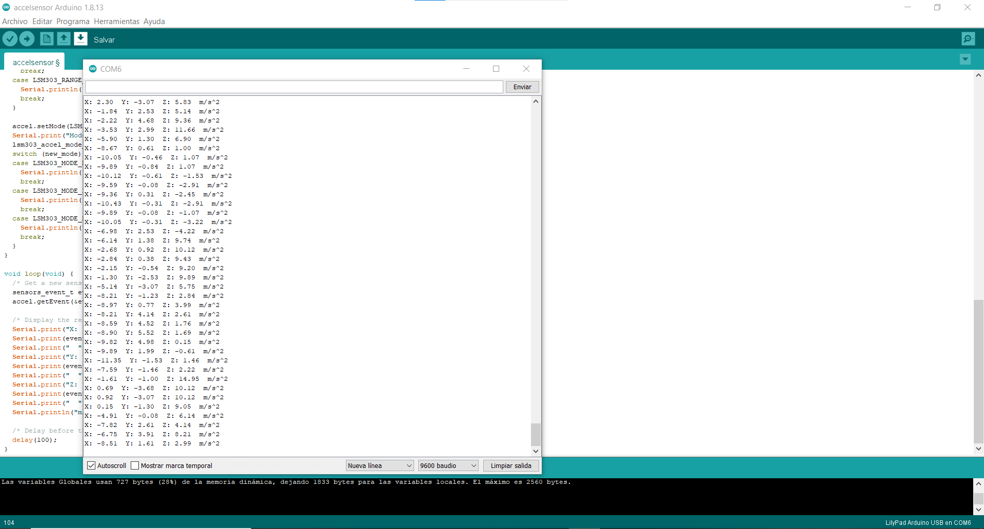
The code I used was an example called Accelsensor from Arduino Adafruit_LSM303 library, in which I made some modifications
#include <Adafruit_LSM303_Accel.h>
#include <Adafruit_Sensor.h>
#include <Wire.h>

/* Assign a unique ID to this sensor at the same time */
Adafruit_LSM303_Accel_Unified accel = Adafruit_LSM303_Accel_Unified(54321);

int led_pin9 = 9;
int led_pin10 = 10;
int led_pin11 = 11;

void displaySensorDetails(void) {
  sensor_t sensor;
  accel.getSensor(&sensor);
  Serial.println("------------------------------------");
  Serial.print("Sensor:       ");
  Serial.println(sensor.name);
  Serial.print("Driver Ver:   ");
  Serial.println(sensor.version);
  Serial.print("Unique ID:    ");
  Serial.println(sensor.sensor_id);
  Serial.print("Max Value:    ");
  Serial.print(sensor.max_value);
  Serial.println(" m/s^2");
  Serial.print("Min Value:    ");
  Serial.print(sensor.min_value);
  Serial.println(" m/s^2");
  Serial.print("Resolution:   ");
  Serial.print(sensor.resolution);
  Serial.println(" m/s^2");
  Serial.println("------------------------------------");
  Serial.println("");
  delay(500);
}

void setup(void) {

   pinMode(led_pin9, OUTPUT);
  pinMode(led_pin10, OUTPUT);
  pinMode(led_pin11, OUTPUT);

#ifndef ESP8266
  while (!Serial)
    ; // will pause Zero, Leonardo, etc until serial console opens
#endif
  Serial.begin(9600);
  Serial.println("Accelerometer Test");
  Serial.println("");

  /* Initialise the sensor */
  if (!accel.begin()) {
    /* There was a problem detecting the ADXL345 ... check your connections */
    Serial.println("Ooops, no LSM303 detected ... Check your wiring!");
    while (1)
      ;
  }

  /* Display some basic information on this sensor */
  displaySensorDetails();

  accel.setRange(LSM303_RANGE_4G);
  Serial.print("Range set to: ");
  lsm303_accel_range_t new_range = accel.getRange();
  switch (new_range) {
  case LSM303_RANGE_2G:
    Serial.println("+- 2G");
    break;
  case LSM303_RANGE_4G:
    Serial.println("+- 4G");
    break;
  case LSM303_RANGE_8G:
    Serial.println("+- 8G");
    break;
  case LSM303_RANGE_16G:
    Serial.println("+- 16G");
    break;
  }

  accel.setMode(LSM303_MODE_NORMAL);
  Serial.print("Mode set to: ");
  lsm303_accel_mode_t new_mode = accel.getMode();
  switch (new_mode) {
  case LSM303_MODE_NORMAL:
    Serial.println("Normal");
    break;
  case LSM303_MODE_LOW_POWER:
    Serial.println("Low Power");
    break;
  case LSM303_MODE_HIGH_RESOLUTION:
    Serial.println("High Resolution");
    break;
  }
}

void loop(void) {
  /* Get a new sensor event */
  sensors_event_t event;
  accel.getEvent(&event);

  /* Display the results (acceleration is measured in m/s^2) */
  Serial.print("X: ");
  Serial.print(event.acceleration.x);
  Serial.print("  ");
  Serial.print("Y: ");
  Serial.print(event.acceleration.y);
  Serial.print("  ");
  Serial.print("Z: ");
  Serial.print(event.acceleration.z);
  Serial.print("  ");
  Serial.println("m/s^2");

  /* Delay before the next sample */
  delay(500);


     if (event.acceleration.x > 4) {
      digitalWrite(led_pin9, HIGH);
     }
     else {
      digitalWrite(led_pin9, LOW);
     }

      if (event.acceleration.y > 4) {
      digitalWrite(led_pin10, HIGH);
     }
     else {
      digitalWrite(led_pin10, LOW);
     }

      if (event.acceleration.z > 9) {
      digitalWrite(led_pin11, HIGH);
     }
     else {
      digitalWrite(led_pin11, LOW);
     }

}
Gallery