3.Process
Project Diary
In this page I will share my final project process; ideas, sketches, tests, suggestions from the reviews, corrections, achievements and also mistakes.
EXPERIMENTATION
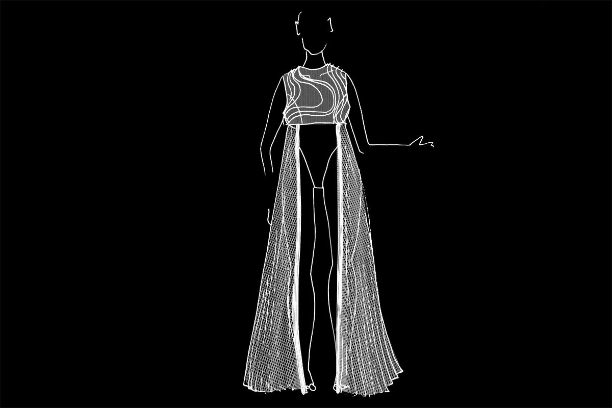
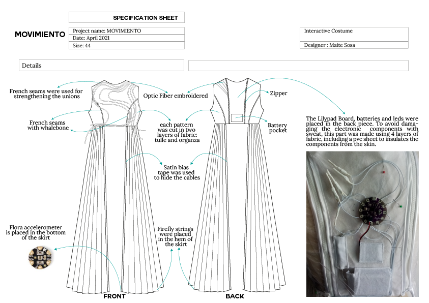
Movimiento
For my final project I intend to investigate how to use technology to amplify the movements of the human body, by designing an interactive costume.
Movimiento: Cambio de lugar o de posición de un cuerpo en el espacio
Movement: A change of place, position or state
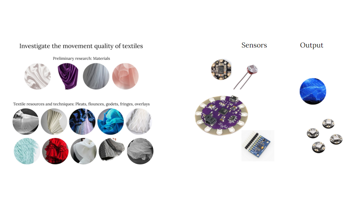
First, my intention is to investigate textile techniques used in garments and costumes that amplify the movements of the person wearing them (such as pleats, flounces, amplitude).
Then, I would like to explore the possibility of incorporating a circuit that contains a sensor (of movement, speed, light) that collects information, which can be transformed into some kind of output, either in the costume itself, for example through light (with leds or fiber optic), or by communicating with other elements that are usually part of the scenes, for example lighting, or visual projection.
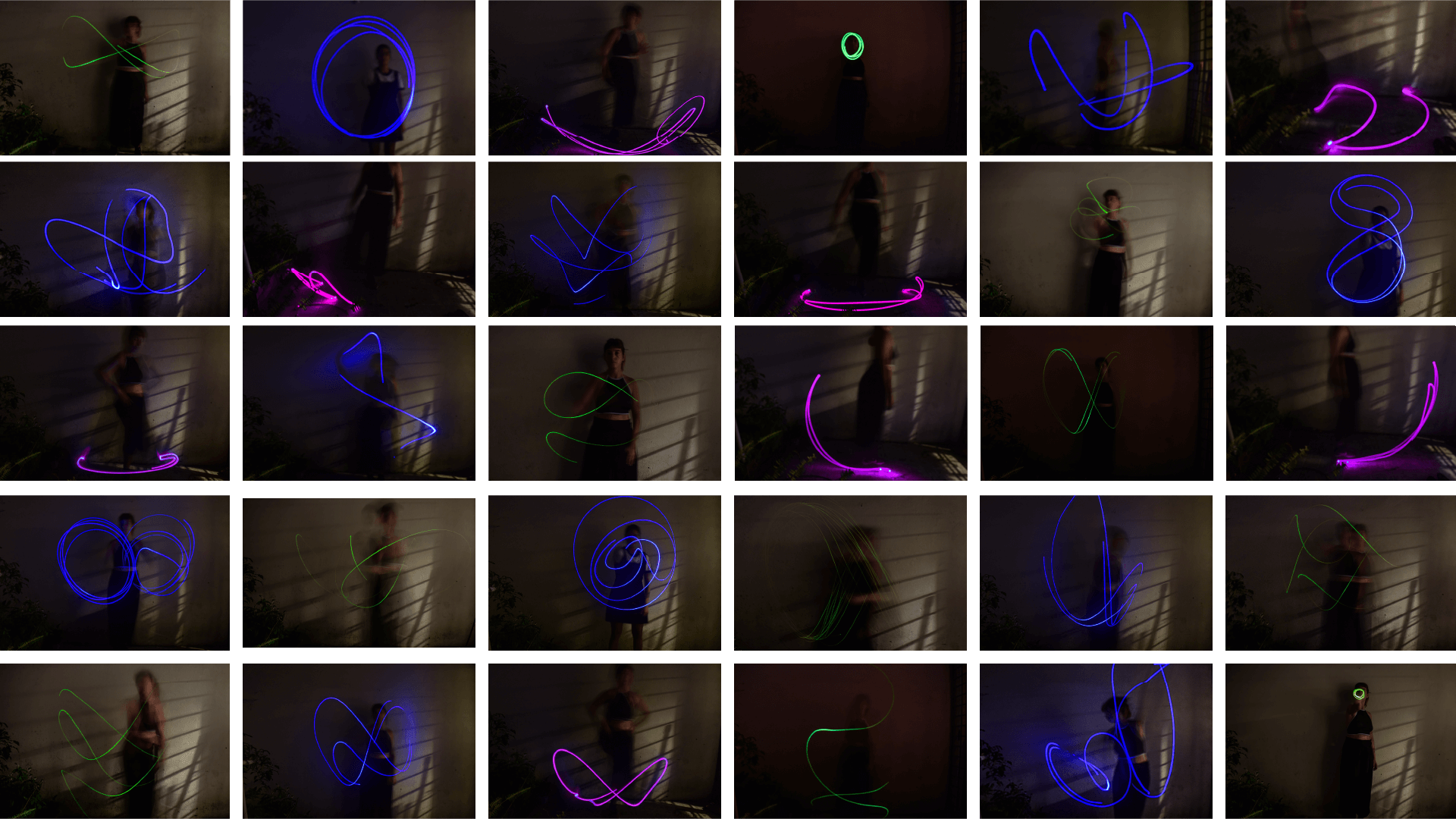
Catálogo de movimientos
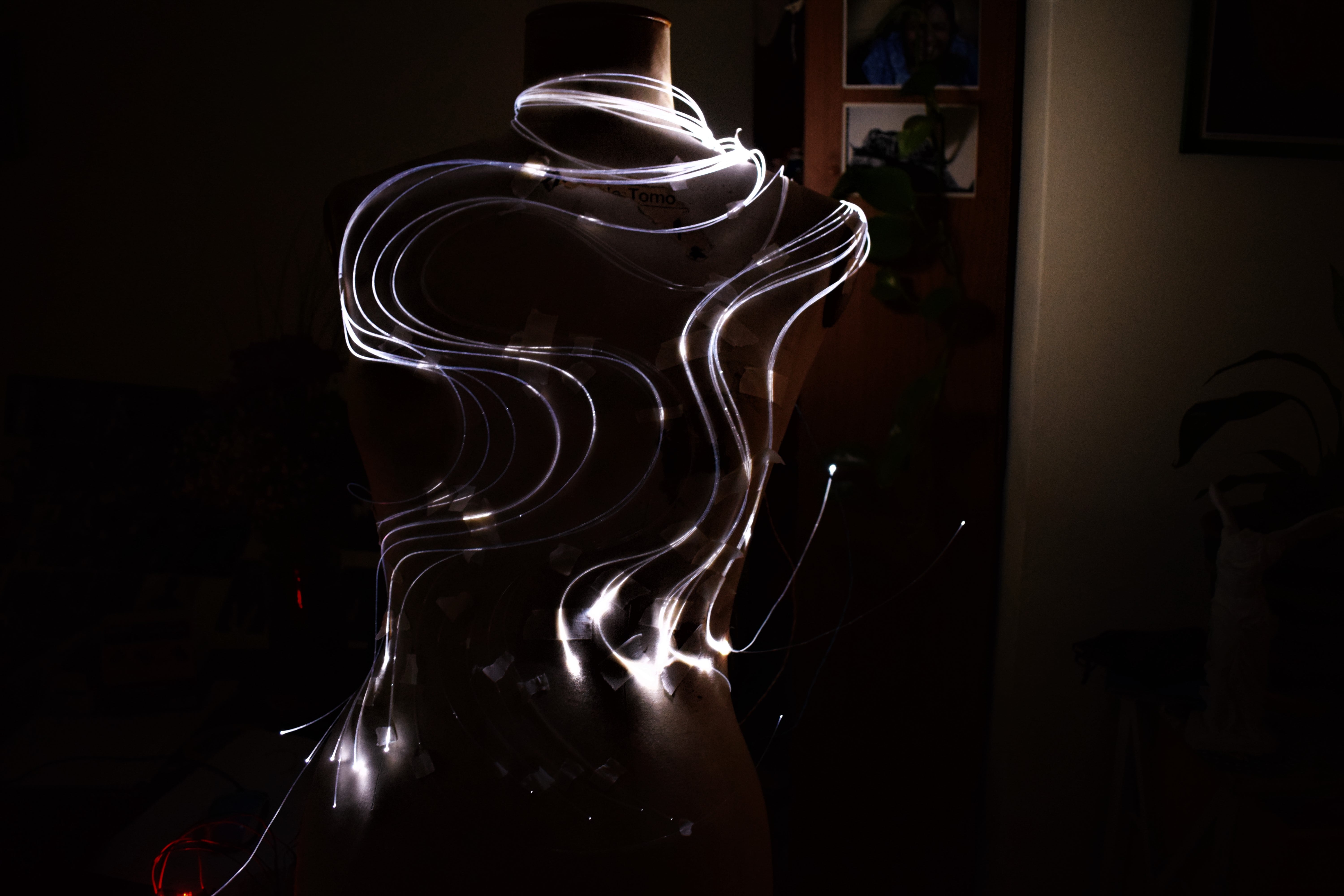
To begin with, I performed a small experiment with a led light, by taking long exposure photos.
Textile Research
_El vestido como espacio flexible
“Si consideramos que la vestimenta constituye el primer espacio del “habitar”, veremos que su conformación morfológica-espacial condiciona y a la vez refleja las prácticas de la vida cotidiana, ya que actúa sin mediaciones sobre el cuerpo en la redefinición (o rediseño) de sus formas y su capacidad de movimiento.
(…)
Existen recursos que permiten crear un movimiento de expansión en las telas y aumentar su elasticidad (…) Por medio de plegados, plisados, drapeados y torsiones se dota a la tela de un movimiento que facilita la adaptación del vestido al cuerpo, elaborando verdaderas estructuras textiles ultralivianas, articuladas con la anatomía. En síntesis, prendas que interactúan con el sujeto, sus movimientos y la expresión de su cuerpo
(…)
Si bien estos casos suponen la transformación del vestido en espacio flexible a partir de la intervención sobre la lámina textil, también se puede proyectar un vestido adaptable al cuerpo mediante las uniones entre los planos que la conforman. Este vestido tendría la capacidad de expandirse o comprimirse en ciertas líneas definidas por la moldería, mediante fuelles, articulaciones, sistemas de rebote que amplíen la distancia entre un plano y otro” (Saltzman, 2014)_
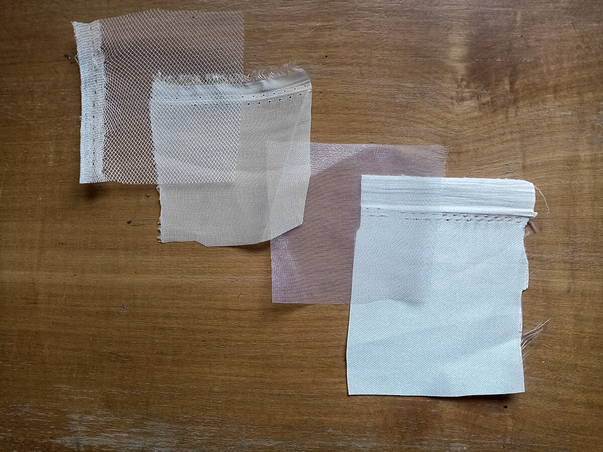
The first few weeks of this research will be used to explore different fabrics and textile techniques that enhance movement.
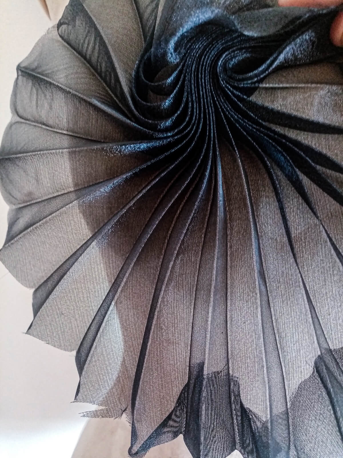
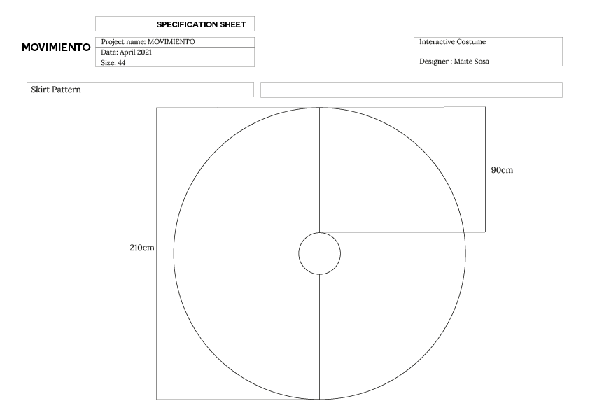
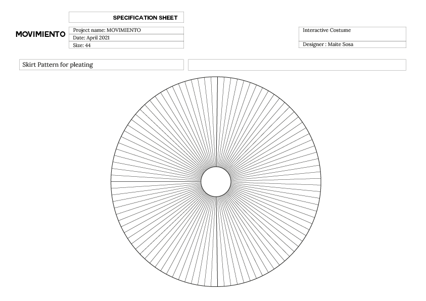
Pleatings
I have always been attracted to the textile technique of pleating; a technique that allows to go from a plane to three-dimensionality, and that generates movement.
Starting with my research, I found Royal College of Art thesis written by Tsai-Chun Huang called IN-BETWEEN PLEATS: Pleats, pleating and 'pliable logic'.
According to the author: "Pleats and pleating have been commonly understood as a type of fabric manipulation that adds extra texture to textiles, or as a process for creating layering effects with fabrics. (...) A pleat is a three dimensional structure, or effect, formed through a process of manipulation, that establishes a fold, or series of folds, or appearance of folds, in material, fabric, or garment" (Huang, 2020:8)
There are several manufacturing process to achieve pleating. Thermal processed pleats are the most common. Hand made pleating can be done by sandwiching fabric between paper moulds and then stablising with heat or steam. This method works with syntenic fabric.
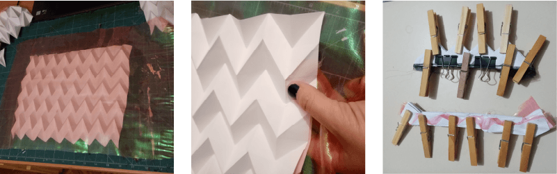
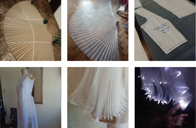
Paper prototypes
To begin to dive into the world of pleating, I started by making paper prototypes.
The book Folding Techniques for Designers: From Sheet to Form (How to fold paper and other materials for design projects) has been very useful and a great source of inspiration.
The first tests were done by hand, following different tutorials (like this and this one) and taking the book as a reference.
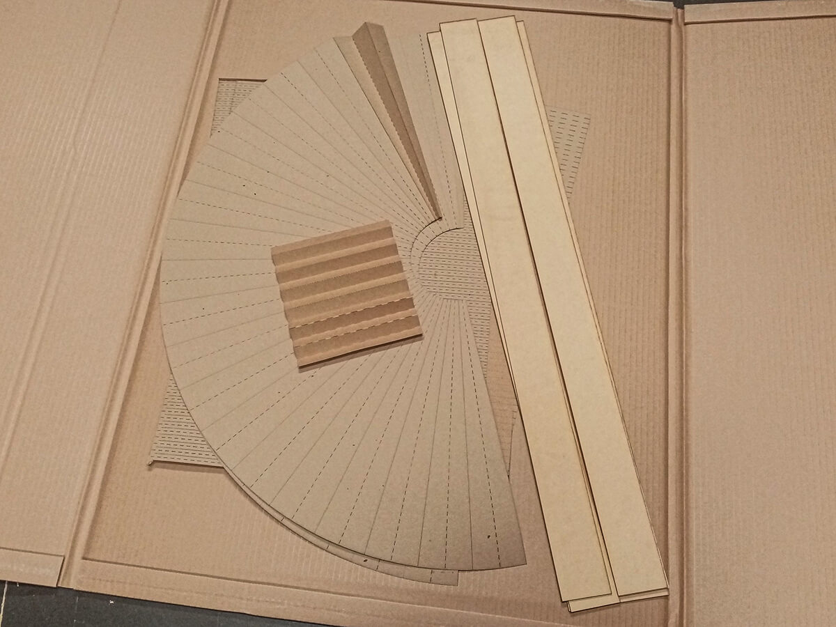
Once I understood the logic, I started to design different patterns using Rhinoceros, which I then transferred to paper using the laser cutting machine.
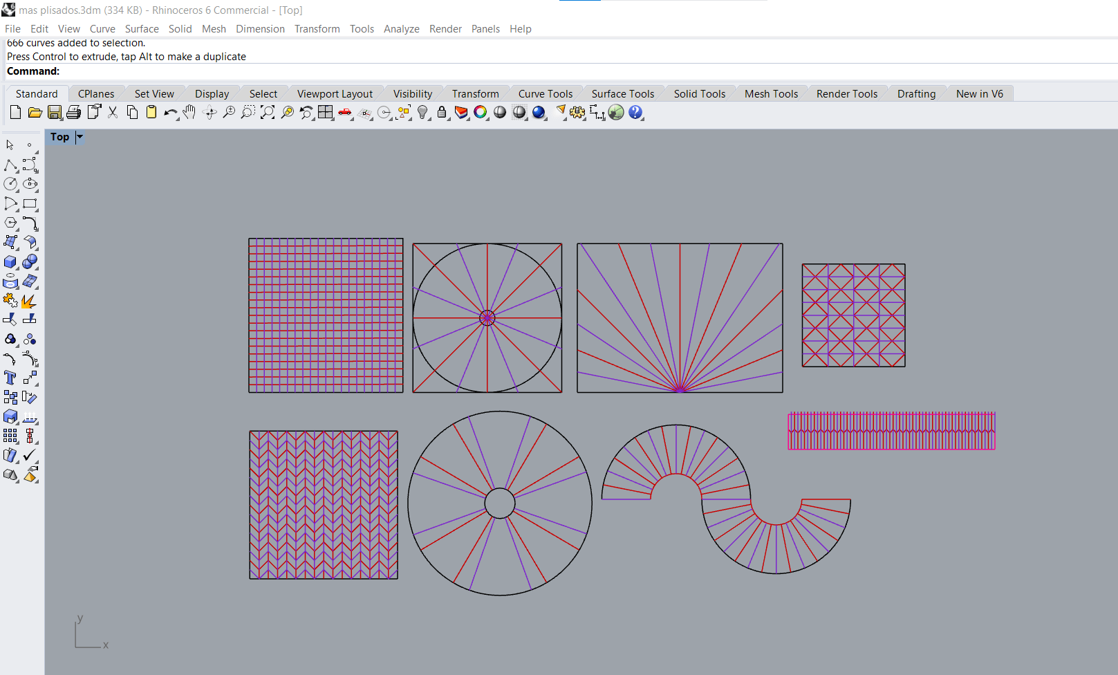
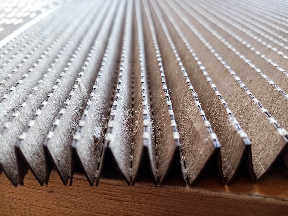
When mechanizing the files, I used very low power, and a very high cutting speed, so that instead of cutting the paper, the laser simply "engraves" or "marks" it. So, instead of having to do each folding by hand, I have the pattern drawn on the paper.
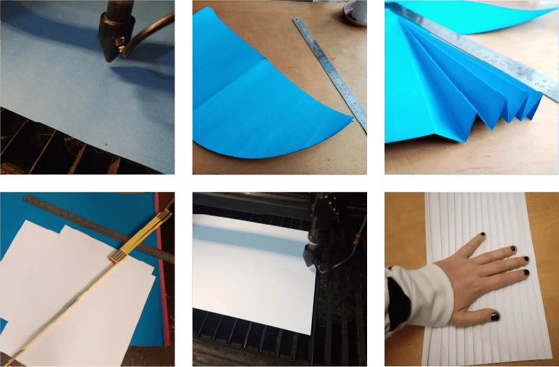


After making a few small samples, I moved on to a larger scale.
Fabric prototypes
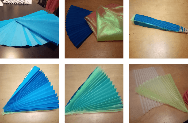
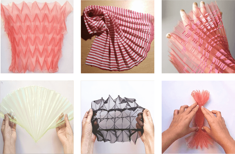
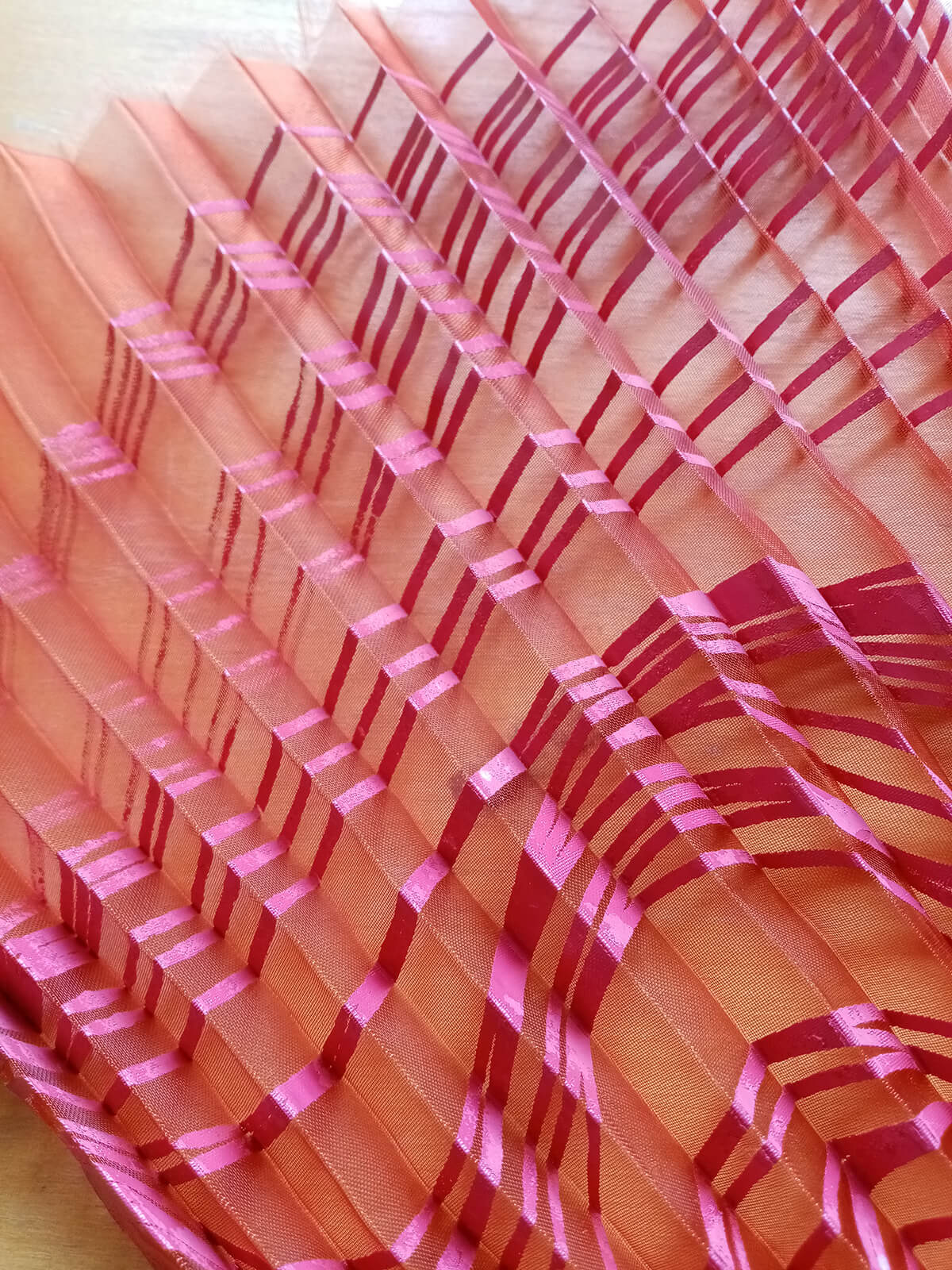
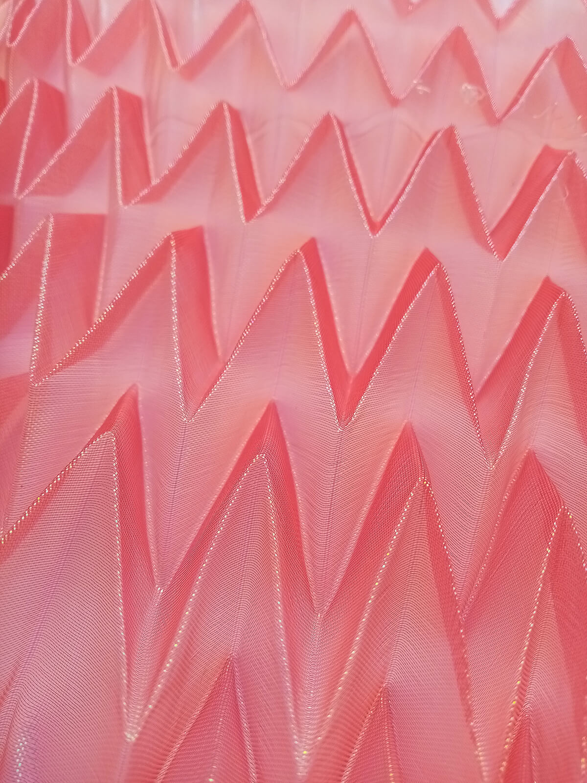
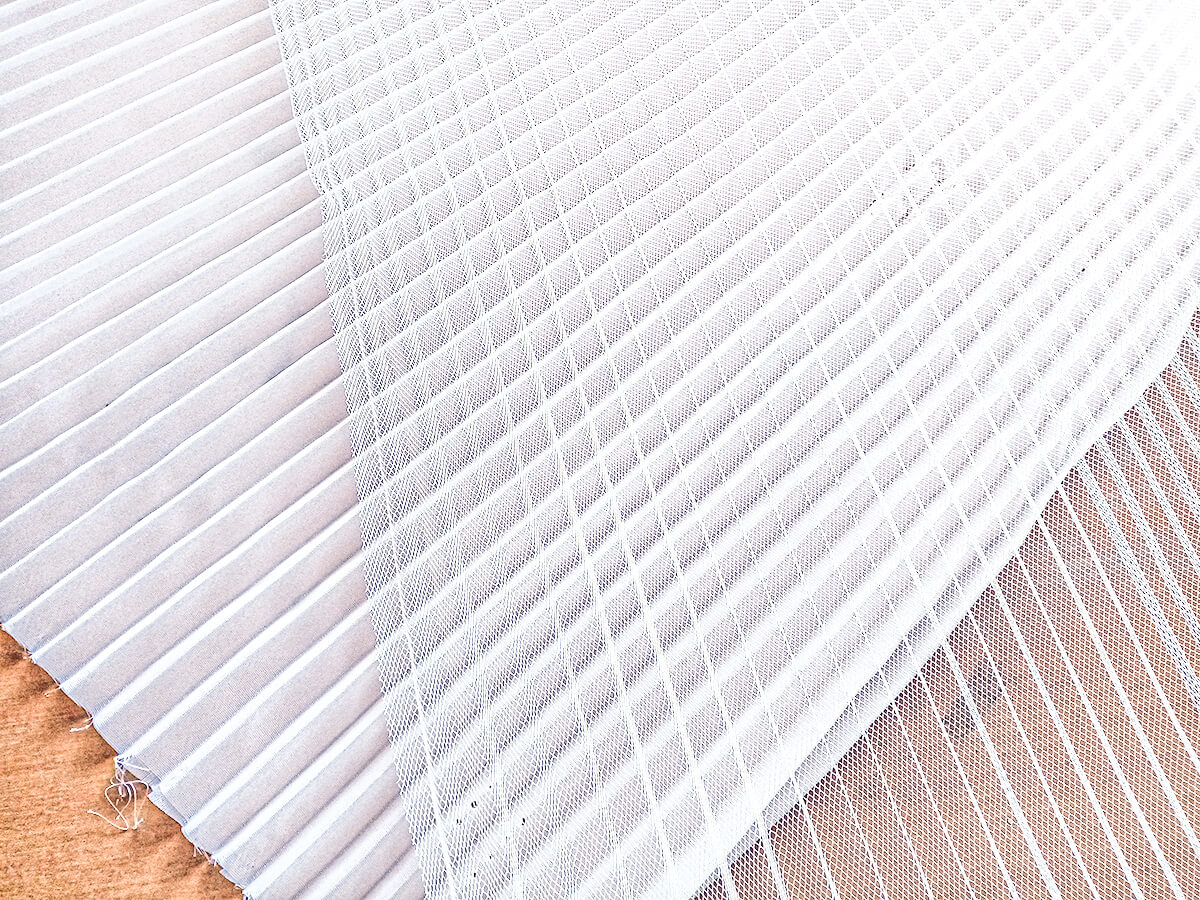
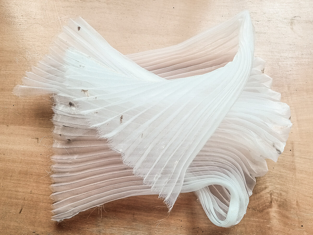
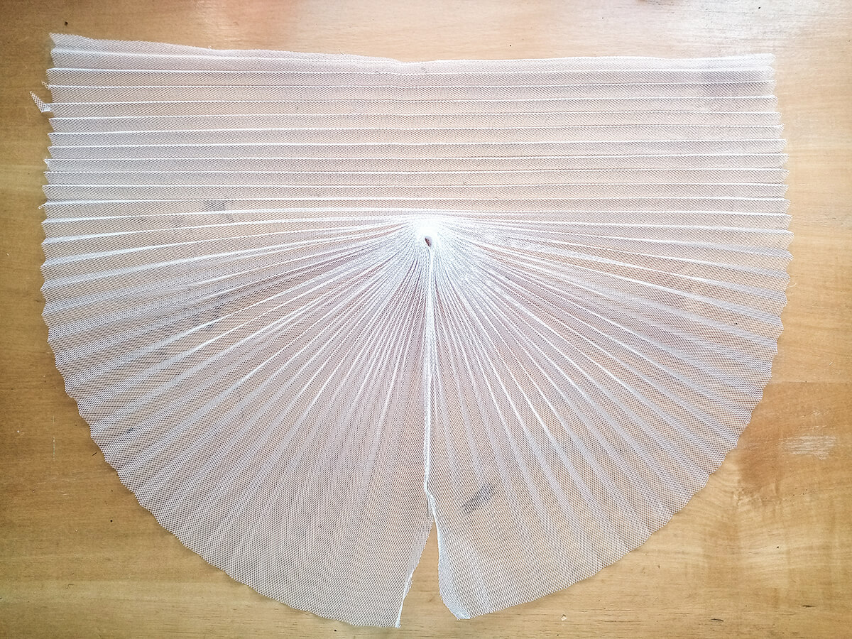
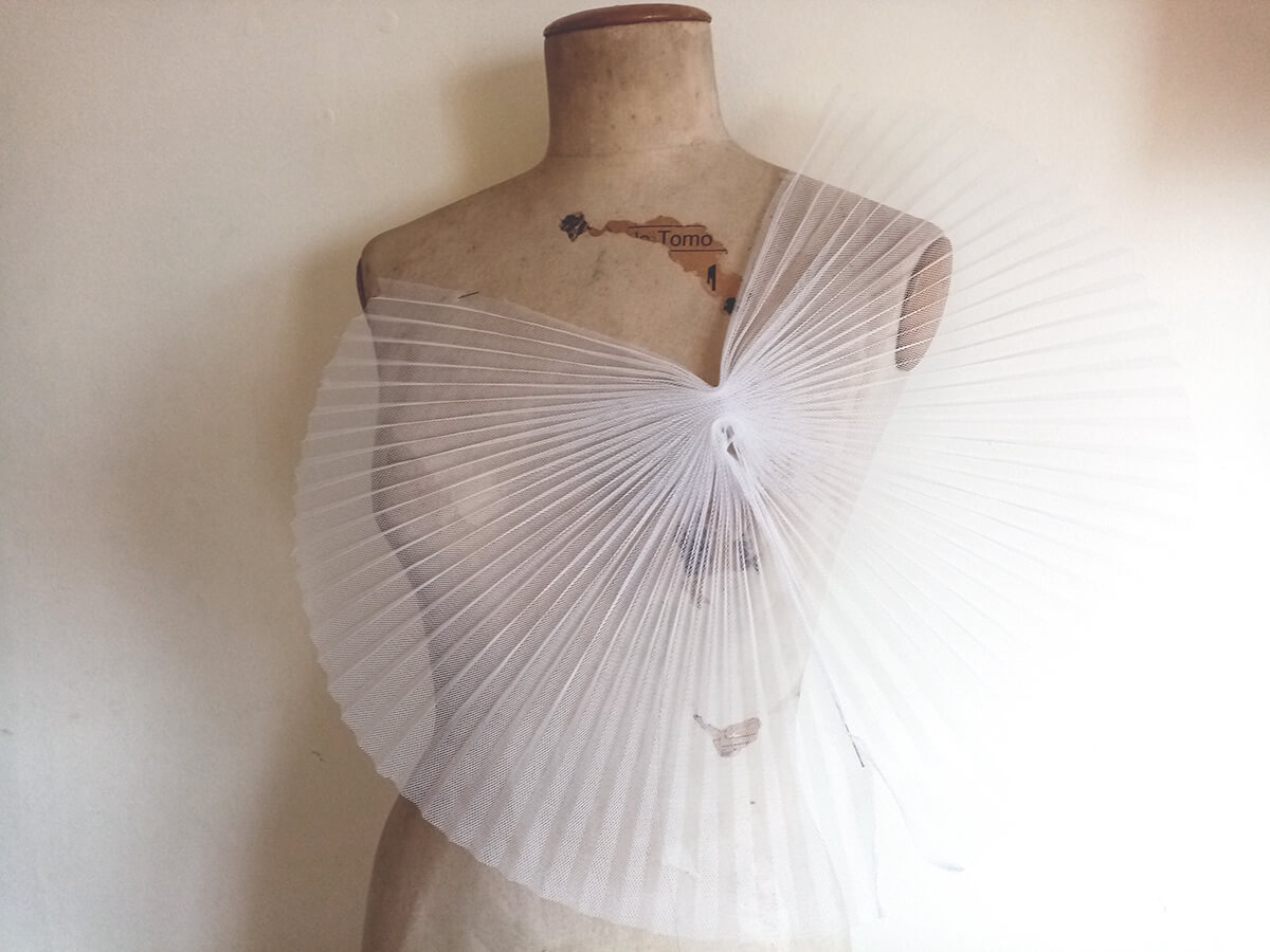

1:1 prototype


Sensors
In addition to experimenting with textiles, during the first weeks of the project I will investigate how to integrate sensors and electronic circuits into an interactive costume.
Accelerometer
SparkFun MPU-9250 9 DOF IMU
To start working with sensors I got in contact with a professor from ALC-IENBA, Marcos Giménez who not only lent me an SparkFun MPU-9250 9 DOF IMU Breakout accelerometer and a LilyPad Arduino USB board, controlled by an ATmega32U4, to start experimenting, but also was an incredible help during the whole process of the project, assisting me with the technical part, both with the assembly of the different circuits and also with the codes of all the tests described below.
This accelerometer is very complex, it is a 9-axis motion tracking device that is ideally suited for smartphones, tablets, wearable sensors, and IoT applications. It has a 3-Axis Gyroscope with four selectable ranges, 3-Axis Accelerometer, again with four selectable ranges, and 3-axis magnetometer.
First I tried putting the circuit together on a protoboard, and started experimenting with the code, installing the Arduino SparkFun MPU-9250 9 DOF IMU Breakout library.
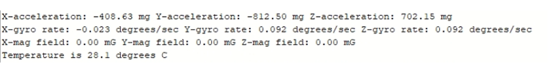
While it was not that difficult to test this sensor, I feel that it is a very complex sensor, and that I may not need to use as much information as the sensor provides in this instance.
MPU-9250 9 DOF IMU Test Code
/* USO BASICO DEL SENSOR MPU925 SparkFun (ACELEROMENTRO, GIROSCOPIO Y MAGNETOMETRO)
Marcos Gimenez
*/

#include "quaternionFilters.h"
#include "MPU9250.h"

#define AHRS false         // En falso para lecturas basicas
#define SerialDebug true  // En true para tener datos en la consola

int intPin = 12;
int myLed  = 13;

//Estos son los pines que voy a usar para el OUTPUT
int led_pin9 = 9;
int led_pin10 = 10;
int led_pin11 = 11;

//Esto define datos para la comunicacion entre el arduino y el sensor, no tiene que ver con los pines sino con el protocolo I2C
#define I2Cclock 400000
#define I2Cport Wire
#define MPU9250_ADDRESS MPU9250_ADDRESS_AD0

MPU9250 myIMU(MPU9250_ADDRESS, I2Cport, I2Cclock);

///////////////////////////////////
void setup()
{
  Wire.begin();
  Serial.begin(38400);

  pinMode(led_pin9, OUTPUT);
  pinMode(led_pin10, OUTPUT);
  pinMode(led_pin11, OUTPUT);

  while(!Serial){};

  //Estos pines pero tienen que ver con la lectura.
  pinMode(intPin, INPUT);
  digitalWrite(intPin, LOW);
  pinMode(myLed, OUTPUT);
  digitalWrite(myLed, HIGH);


  // Lee los datos del sensor al iniciar
  byte c = myIMU.readByte(MPU9250_ADDRESS, WHO_AM_I_MPU9250);
  Serial.print(F("MPU9250 I AM 0x"));
  Serial.print(c, HEX);
  Serial.print(F(" I should be 0x"));
  Serial.println(0x71, HEX);


  if (c == 0x70) // 0x70 es la direccion en la que se conecta la arduino al sensor en el protocolo I2C
  {
    Serial.println(F("MPU9250 is online..."));

    // Test de valores iniciales
    myIMU.MPU9250SelfTest(myIMU.selfTest);
    Serial.print(F("x-axis self test: acceleration trim within : "));
    Serial.print(myIMU.selfTest[0],1); Serial.println("% of factory value");
    Serial.print(F("y-axis self test: acceleration trim within : "));
    Serial.print(myIMU.selfTest[1],1); Serial.println("% of factory value");
    Serial.print(F("z-axis self test: acceleration trim within : "));
    Serial.print(myIMU.selfTest[2],1); Serial.println("% of factory value");
    Serial.print(F("x-axis self test: gyration trim within : "));
    Serial.print(myIMU.selfTest[3],1); Serial.println("% of factory value");
    Serial.print(F("y-axis self test: gyration trim within : "));
    Serial.print(myIMU.selfTest[4],1); Serial.println("% of factory value");
    Serial.print(F("z-axis self test: gyration trim within : "));
    Serial.print(myIMU.selfTest[5],1); Serial.println("% of factory value");

    // Se calibra el sensor con los valores obtenidos.
    myIMU.calibrateMPU9250(myIMU.gyroBias, myIMU.accelBias);

    // Se inicializa el el giroscopio, el aceleromentro y la temperatura
    myIMU.initMPU9250();
    Serial.println("MPU9250 initialized for active data mode....");

    // Se leen los datos del magnetometro.
    byte d = myIMU.readByte(AK8963_ADDRESS, WHO_AM_I_AK8963);
    Serial.print("AK8963 ");
    Serial.print("I AM 0x");
    Serial.print(d, HEX);
    Serial.print(" I should be 0x");
    Serial.println(0x48, HEX);

    if (d != 0xFF) //0xFF es la direccion del magnetometro en el protocolo I2C
    {
      // Fallo la comunicacion
      Serial.println(F("Communication failed, abort!"));
      Serial.flush();
      abort();
    }

    // Se calibra el magnetometro y se inicializa
    myIMU.initAK8963(myIMU.factoryMagCalibration);
    Serial.println("AK8963 initialized for active data mode....");

    if (SerialDebug)
    {
      //  Se imprimine valores de calibracion
      Serial.print("X-Axis factory sensitivity adjustment value ");
      Serial.println(myIMU.factoryMagCalibration[0], 2);
      Serial.print("Y-Axis factory sensitivity adjustment value ");
      Serial.println(myIMU.factoryMagCalibration[1], 2);
      Serial.print("Z-Axis factory sensitivity adjustment value ");
      Serial.println(myIMU.factoryMagCalibration[2], 2);
    }

    // Resolucion del sensor, se ejecuta solo una vez (No sé realmente que significa "resolucion")
    myIMU.getAres();
    myIMU.getGres();
    myIMU.getMres();

    // The next call delays for 4 seconds, and then records about 15 seconds of
    // data to calculate bias and scale.
    //myIMU.magCalMPU9250(myIMU.magBias, myIMU.magScale);
    Serial.println("AK8963 mag biases (mG)");
    Serial.println(myIMU.magBias[0]);
    Serial.println(myIMU.magBias[1]);
    Serial.println(myIMU.magBias[2]);

    Serial.println("AK8963 mag scale (mG)");
    Serial.println(myIMU.magScale[0]);
    Serial.println(myIMU.magScale[1]);
    Serial.println(myIMU.magScale[2]);
//  delay(2000); // Add delay to see results before serial spew of data

    if(SerialDebug)
    {
      Serial.println("Magnetometer:");
      Serial.print("X-Axis sensitivity adjustment value ");
      Serial.println(myIMU.factoryMagCalibration[0], 2);
      Serial.print("Y-Axis sensitivity adjustment value ");
      Serial.println(myIMU.factoryMagCalibration[1], 2);
      Serial.print("Z-Axis sensitivity adjustment value ");
      Serial.println(myIMU.factoryMagCalibration[2], 2);
    }
  }
  else
  {
    Serial.print("Could not connect to MPU9250: 0x");
    Serial.println(c, HEX);

    // Communication failed, stop here
    Serial.println(F("Communication failed, abort!"));
    Serial.flush();
    abort();
  }
}

void loop()
{

  // If intPin goes high, all data registers have new data
  // On interrupt, check if data ready interrupt
  if (myIMU.readByte(MPU9250_ADDRESS, INT_STATUS) & 0x01)
  {
    myIMU.readAccelData(myIMU.accelCount);  // Read the x/y/z adc values

    // Now we'll calculate the accleration value into actual g's
    // This depends on scale being set
    myIMU.ax = (float)myIMU.accelCount[0] * myIMU.aRes; // - myIMU.accelBias[0];
    myIMU.ay = (float)myIMU.accelCount[1] * myIMU.aRes; // - myIMU.accelBias[1];
    myIMU.az = (float)myIMU.accelCount[2] * myIMU.aRes; // - myIMU.accelBias[2];

    myIMU.readGyroData(myIMU.gyroCount);  // Read the x/y/z adc values

    // Calculate the gyro value into actual degrees per second
    // This depends on scale being set
    myIMU.gx = (float)myIMU.gyroCount[0] * myIMU.gRes;
    myIMU.gy = (float)myIMU.gyroCount[1] * myIMU.gRes;
    myIMU.gz = (float)myIMU.gyroCount[2] * myIMU.gRes;

    myIMU.readMagData(myIMU.magCount);  // Read the x/y/z adc values

    // Calculate the magnetometer values in milliGauss
    // Include factory calibration per data sheet and user environmental
    // corrections
    // Get actual magnetometer value, this depends on scale being set
    myIMU.mx = (float)myIMU.magCount[0] * myIMU.mRes
               * myIMU.factoryMagCalibration[0] - myIMU.magBias[0];
    myIMU.my = (float)myIMU.magCount[1] * myIMU.mRes
               * myIMU.factoryMagCalibration[1] - myIMU.magBias[1];
    myIMU.mz = (float)myIMU.magCount[2] * myIMU.mRes
               * myIMU.factoryMagCalibration[2] - myIMU.magBias[2];
  } // if (readByte(MPU9250_ADDRESS, INT_STATUS) & 0x01)

  // Must be called before updating quaternions!
  myIMU.updateTime();

  // Sensors x (y)-axis of the accelerometer is aligned with the y (x)-axis of
  // the magnetometer; the magnetometer z-axis (+ down) is opposite to z-axis
  // (+ up) of accelerometer and gyro! We have to make some allowance for this
  // orientationmismatch in feeding the output to the quaternion filter. For the
  // MPU-9250, we have chosen a magnetic rotation that keeps the sensor forward
  // along the x-axis just like in the LSM9DS0 sensor. This rotation can be
  // modified to allow any convenient orientation convention. This is ok by
  // aircraft orientation standards! Pass gyro rate as rad/s
  MahonyQuaternionUpdate(myIMU.ax, myIMU.ay, myIMU.az, myIMU.gx * DEG_TO_RAD,
                         myIMU.gy * DEG_TO_RAD, myIMU.gz * DEG_TO_RAD, myIMU.my,
                         myIMU.mx, myIMU.mz, myIMU.deltat);

  if (!AHRS)
  {
    myIMU.delt_t = millis() - myIMU.count;
    if (myIMU.delt_t > 500)
    {
      if(SerialDebug)
      {
        // Print acceleration values in milligs!
        Serial.print("X-acceleration: "); Serial.print(1000 * myIMU.ax);
        Serial.print(" mg ");
        Serial.print("Y-acceleration: "); Serial.print(1000 * myIMU.ay);
        Serial.print(" mg ");
        Serial.print("Z-acceleration: "); Serial.print(1000 * myIMU.az);
        Serial.println(" mg ");

        // Print gyro values in degree/sec
        Serial.print("X-gyro rate: "); Serial.print(myIMU.gx, 3);
        Serial.print(" degrees/sec ");
        Serial.print("Y-gyro rate: "); Serial.print(myIMU.gy, 3);
        Serial.print(" degrees/sec ");
        Serial.print("Z-gyro rate: "); Serial.print(myIMU.gz, 3);
        Serial.println(" degrees/sec");

        // Print mag values in degree/sec
        Serial.print("X-mag field: "); Serial.print(myIMU.mx);
        Serial.print(" mG ");
        Serial.print("Y-mag field: "); Serial.print(myIMU.my);
        Serial.print(" mG ");
        Serial.print("Z-mag field: "); Serial.print(myIMU.mz);
        Serial.println(" mG");

        myIMU.tempCount = myIMU.readTempData();  // Read the adc values
        // Temperature in degrees Centigrade
        myIMU.temperature = ((float) myIMU.tempCount) / 333.87 + 21.0;
        // Print temperature in degrees Centigrade
        Serial.print("Temperature is ");  Serial.print(myIMU.temperature, 1);
        Serial.println(" degrees C");
      }

      myIMU.count = millis();
      digitalWrite(myLed, !digitalRead(myLed));  // toggle led
    } // if (myIMU.delt_t > 500)
  }

  else
  {
    // Serial print and/or display at 0.5 s rate independent of data rates
    myIMU.delt_t = millis() - myIMU.count;

    // update LCD once per half-second independent of read rate
    if (myIMU.delt_t > 500)
    {
      if(SerialDebug)
      {
        Serial.print("ax = ");  Serial.print((int)1000 * myIMU.ax);
        Serial.print(" ay = "); Serial.print((int)1000 * myIMU.ay);
        Serial.print(" az = "); Serial.print((int)1000 * myIMU.az);
        Serial.println(" mg");

        Serial.print("gx = ");  Serial.print(myIMU.gx, 2);
        Serial.print(" gy = "); Serial.print(myIMU.gy, 2);
        Serial.print(" gz = "); Serial.print(myIMU.gz, 2);
        Serial.println(" deg/s");

        Serial.print("mx = ");  Serial.print((int)myIMU.mx);
        Serial.print(" my = "); Serial.print((int)myIMU.my);
        Serial.print(" mz = "); Serial.print((int)myIMU.mz);
        Serial.println(" mG");

        Serial.print("q0 = ");  Serial.print(*getQ());
        Serial.print(" qx = "); Serial.print(*(getQ() + 1));
        Serial.print(" qy = "); Serial.print(*(getQ() + 2));
        Serial.print(" qz = "); Serial.println(*(getQ() + 3));
      }

// Define output variables from updated quaternion---these are Tait-Bryan
// angles, commonly used in aircraft orientation. In this coordinate system,
// the positive z-axis is down toward Earth. Yaw is the angle between Sensor
// x-axis and Earth magnetic North (or true North if corrected for local
// declination, looking down on the sensor positive yaw is counterclockwise.
// Pitch is angle between sensor x-axis and Earth ground plane, toward the
// Earth is positive, up toward the sky is negative. Roll is angle between
// sensor y-axis and Earth ground plane, y-axis up is positive roll. These
// arise from the definition of the homogeneous rotation matrix constructed
// from quaternions. Tait-Bryan angles as well as Euler angles are
// non-commutative; that is, the get the correct orientation the rotations
// must be applied in the correct order which for this configuration is yaw,
// pitch, and then roll.
// For more see
// http://en.wikipedia.org/wiki/Conversion_between_quaternions_and_Euler_angles
// which has additional links.
      myIMU.yaw   = atan2(2.0f * (*(getQ()+1) * *(getQ()+2) + *getQ()
                    * *(getQ()+3)), *getQ() * *getQ() + *(getQ()+1)
                    * *(getQ()+1) - *(getQ()+2) * *(getQ()+2) - *(getQ()+3)
                    * *(getQ()+3));
      myIMU.pitch = -asin(2.0f * (*(getQ()+1) * *(getQ()+3) - *getQ()
                    * *(getQ()+2)));
      myIMU.roll  = atan2(2.0f * (*getQ() * *(getQ()+1) + *(getQ()+2)
                    * *(getQ()+3)), *getQ() * *getQ() - *(getQ()+1)
                    * *(getQ()+1) - *(getQ()+2) * *(getQ()+2) + *(getQ()+3)
                    * *(getQ()+3));
      myIMU.pitch *= RAD_TO_DEG;
      myIMU.yaw   *= RAD_TO_DEG;

      // Declination of SparkFun Electronics (40°05'26.6"N 105°11'05.9"W) is
      //    8° 30' E  ± 0° 21' (or 8.5°) on 2016-07-19
      // - http://www.ngdc.noaa.gov/geomag-web/#declination
      myIMU.yaw  -= 8.5;
      myIMU.roll *= RAD_TO_DEG;

      if(SerialDebug)
      {
        Serial.print("Yaw, Pitch, Roll: ");
        Serial.print(myIMU.yaw, 2);
        Serial.print(", ");
        Serial.print(myIMU.pitch, 2);
        Serial.print(", ");
        Serial.println(myIMU.roll, 2);

        Serial.print("rate = ");
        Serial.print((float)myIMU.sumCount / myIMU.sum, 2);
        Serial.println(" Hz");
      }

      myIMU.count = millis();
      myIMU.sumCount = 0;
      myIMU.sum = 0;
    } // if (myIMU.delt_t > 500)
  } // if (AHRS)


 if (myIMU.temperature > 28.5) {
      digitalWrite(led_pin9, HIGH);
     }

     else {
      digitalWrite(led_pin9, LOW);
     }

}
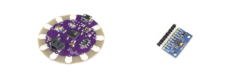
FLORA Accelerometer/Compass Sensor - LSM303
Luckily, I was able to get a FLORA Accelerometer/Compass Sensor - LSM303, as well as a LilyPad Arduino USB board, controlled by an ATmega32U4.
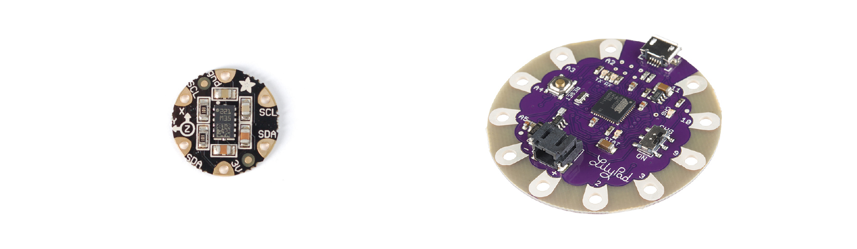
In Adafruit site I found information on how the sensor works, and how the basic connections are made. Inside LSM303 there are two sensors, a 3-axis accelerometer, which can tell you which direction is down towards the Earth (by measuring gravity) or how fast the board is accelerating in 3D space. The other is a magnetometer that can sense where the strongest magnetic force is coming from, generally used to detect magnetic north.
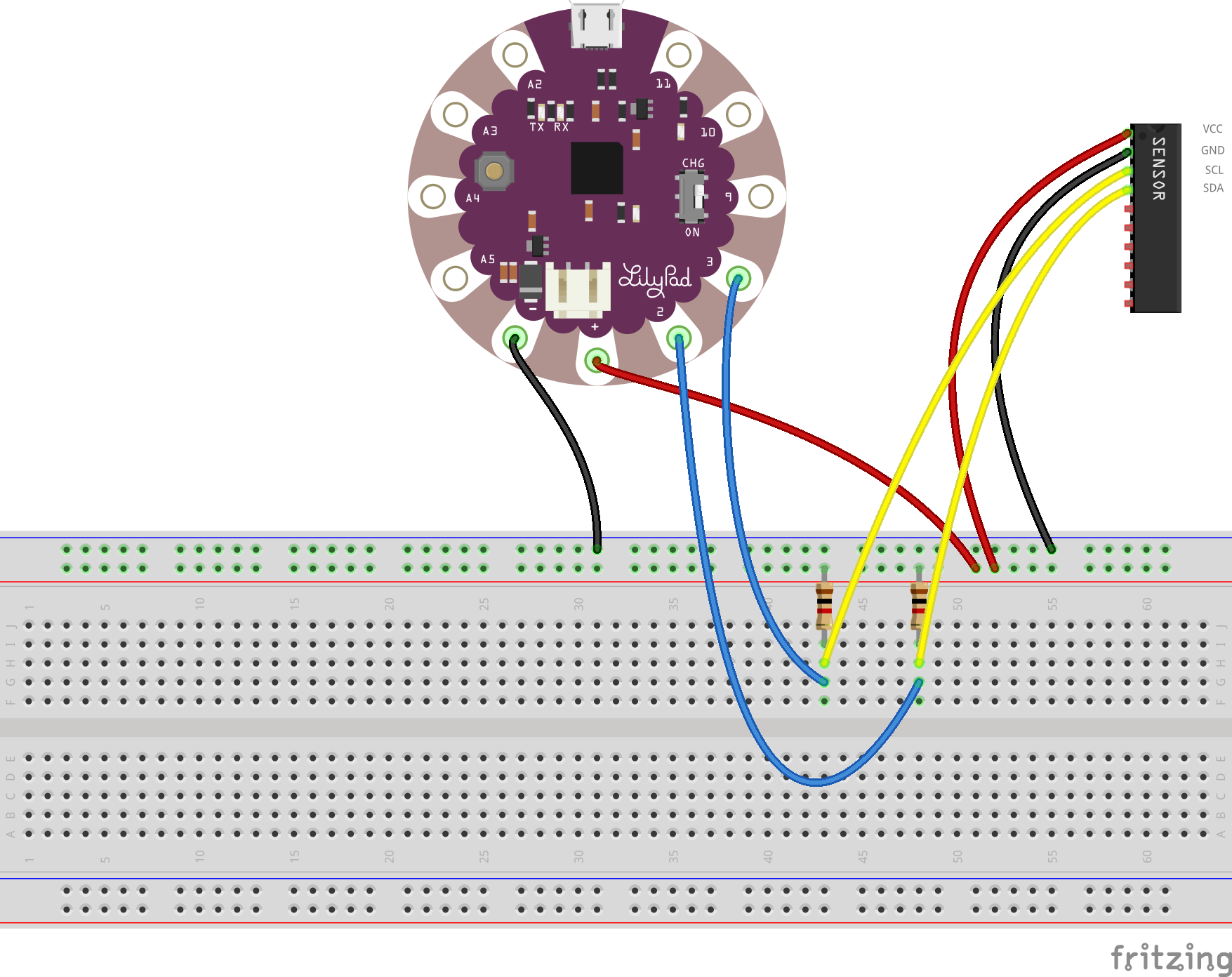
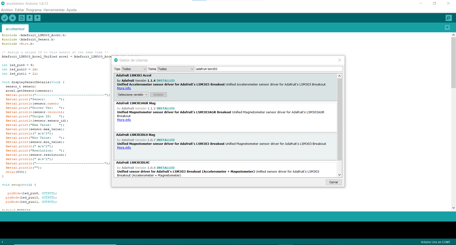
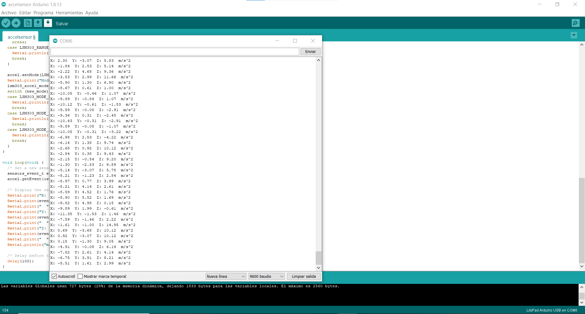
First I tried simply putting the circuit together on a protoboard, and started experimenting with the code, installing the Arduino Adafruit_LSM303 library and testing an example of it.
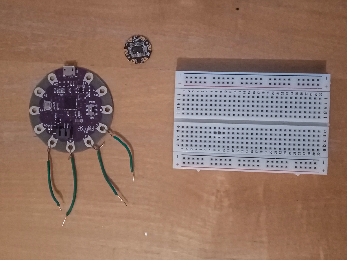
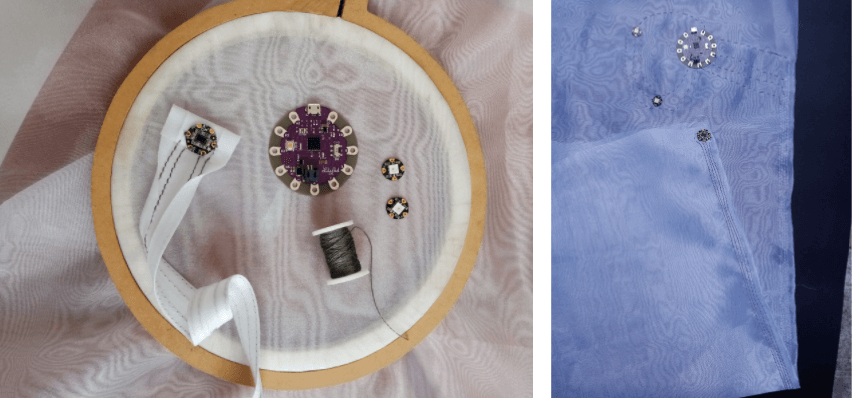
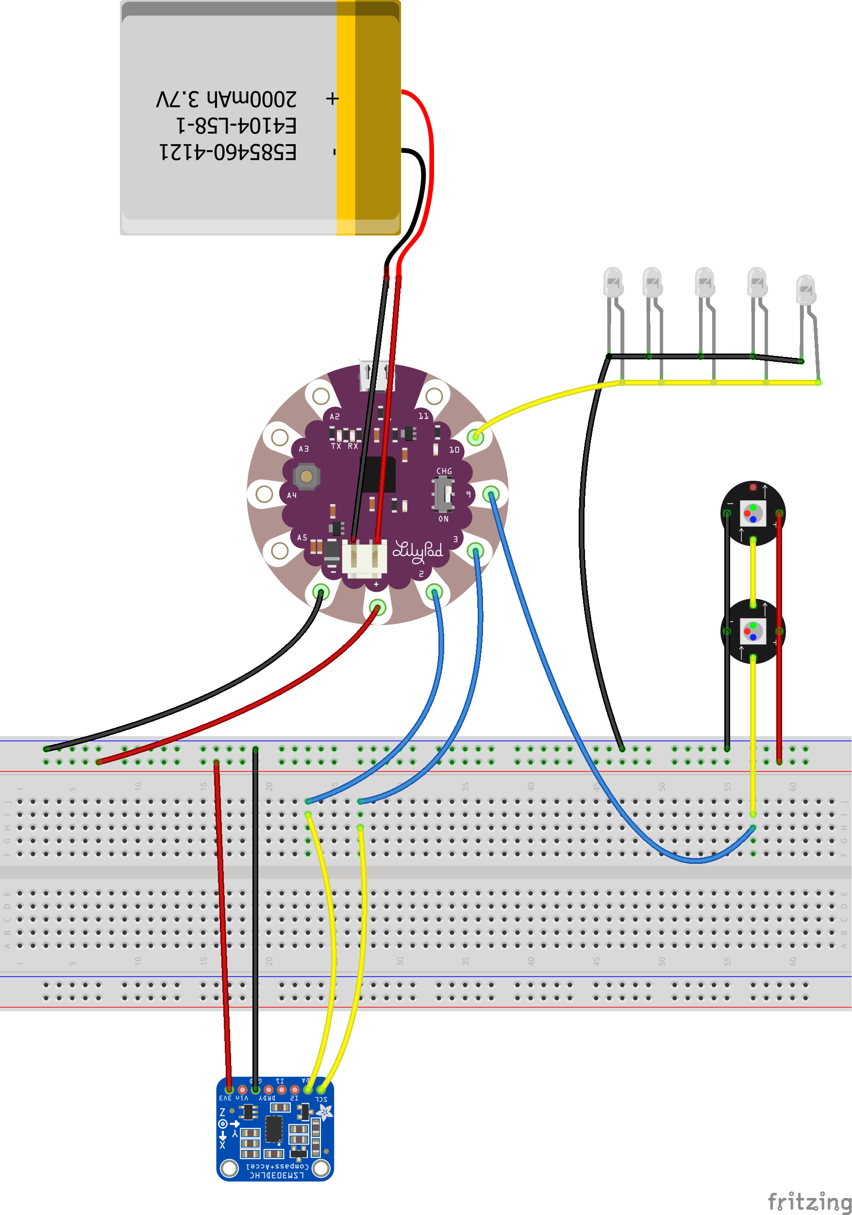
Once I understood the basic connections, I tried assembling a textile swatch, with the microcontroller, the sensor, and three LEDs connected to three different pins of the Lilypad.
Testing Accelerometer from Maite Sosa on Vimeo.
Code
The code I used was an example called Accelsensor from Arduino Adafruit_LSM303 library, in which I made some modifications
#include <Adafruit_LSM303_Accel.h>
#include <Adafruit_Sensor.h>
#include <Wire.h>

/* Assign a unique ID to this sensor at the same time */
Adafruit_LSM303_Accel_Unified accel = Adafruit_LSM303_Accel_Unified(54321);

int led_pin9 = 9;
int led_pin10 = 10;
int led_pin11 = 11;

void displaySensorDetails(void) {
  sensor_t sensor;
  accel.getSensor(&sensor);
  Serial.println("------------------------------------");
  Serial.print("Sensor:       ");
  Serial.println(sensor.name);
  Serial.print("Driver Ver:   ");
  Serial.println(sensor.version);
  Serial.print("Unique ID:    ");
  Serial.println(sensor.sensor_id);
  Serial.print("Max Value:    ");
  Serial.print(sensor.max_value);
  Serial.println(" m/s^2");
  Serial.print("Min Value:    ");
  Serial.print(sensor.min_value);
  Serial.println(" m/s^2");
  Serial.print("Resolution:   ");
  Serial.print(sensor.resolution);
  Serial.println(" m/s^2");
  Serial.println("------------------------------------");
  Serial.println("");
  delay(500);
}

void setup(void) {

   pinMode(led_pin9, OUTPUT);
  pinMode(led_pin10, OUTPUT);
  pinMode(led_pin11, OUTPUT);

#ifndef ESP8266
  while (!Serial)
    ; // will pause Zero, Leonardo, etc until serial console opens
#endif
  Serial.begin(9600);
  Serial.println("Accelerometer Test");
  Serial.println("");

  /* Initialise the sensor */
  if (!accel.begin()) {
    /* There was a problem detecting the ADXL345 ... check your connections */
    Serial.println("Ooops, no LSM303 detected ... Check your wiring!");
    while (1)
      ;
  }

  /* Display some basic information on this sensor */
  displaySensorDetails();

  accel.setRange(LSM303_RANGE_4G);
  Serial.print("Range set to: ");
  lsm303_accel_range_t new_range = accel.getRange();
  switch (new_range) {
  case LSM303_RANGE_2G:
    Serial.println("+- 2G");
    break;
  case LSM303_RANGE_4G:
    Serial.println("+- 4G");
    break;
  case LSM303_RANGE_8G:
    Serial.println("+- 8G");
    break;
  case LSM303_RANGE_16G:
    Serial.println("+- 16G");
    break;
  }

  accel.setMode(LSM303_MODE_NORMAL);
  Serial.print("Mode set to: ");
  lsm303_accel_mode_t new_mode = accel.getMode();
  switch (new_mode) {
  case LSM303_MODE_NORMAL:
    Serial.println("Normal");
    break;
  case LSM303_MODE_LOW_POWER:
    Serial.println("Low Power");
    break;
  case LSM303_MODE_HIGH_RESOLUTION:
    Serial.println("High Resolution");
    break;
  }
}

void loop(void) {
  /* Get a new sensor event */
  sensors_event_t event;
  accel.getEvent(&event);

  /* Display the results (acceleration is measured in m/s^2) */
  Serial.print("X: ");
  Serial.print(event.acceleration.x);
  Serial.print("  ");
  Serial.print("Y: ");
  Serial.print(event.acceleration.y);
  Serial.print("  ");
  Serial.print("Z: ");
  Serial.print(event.acceleration.z);
  Serial.print("  ");
  Serial.println("m/s^2");

  /* Delay before the next sample */
  delay(500);


     if (event.acceleration.x > 4) {
      digitalWrite(led_pin9, HIGH);
     }
     else {
      digitalWrite(led_pin9, LOW);
     }

      if (event.acceleration.y > 4) {
      digitalWrite(led_pin10, HIGH);
     }
     else {
      digitalWrite(led_pin10, LOW);
     }

      if (event.acceleration.z > 9) {
      digitalWrite(led_pin11, HIGH);
     }
     else {
      digitalWrite(led_pin11, LOW);
     }

}
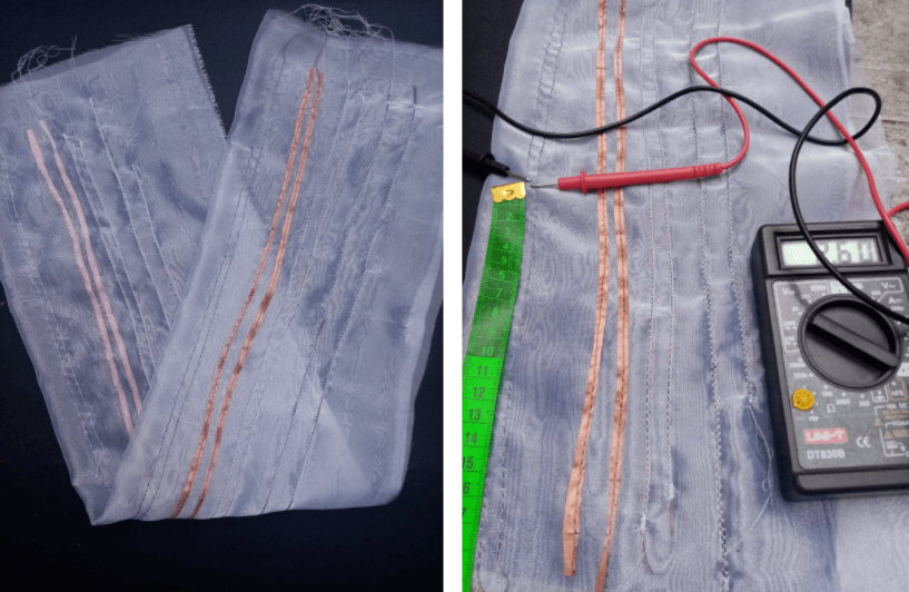
After making a small swatch, I decided to move to a larger scale, since my plan is to place the accelerometer in the lower part of the costume. For that reason, I made a new swatch with 85cm long seams, and I couldn't make the circuit work. I found that with the conductive thread, there is too much resistance in the long seams.
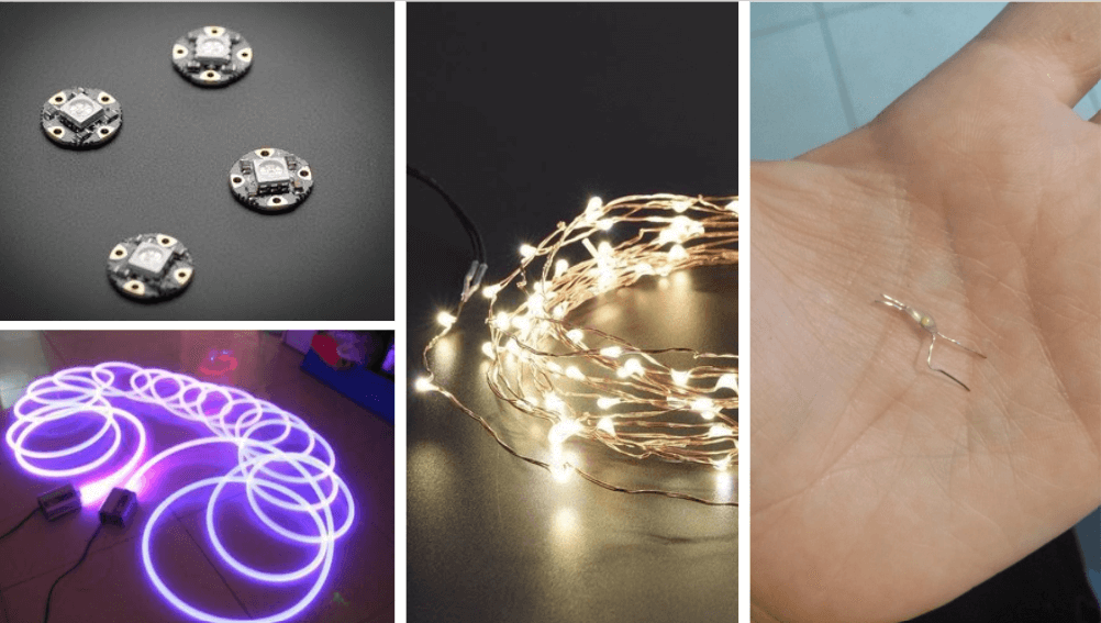
Output
For this project, I intend to enhance the movement of the human body using light as an output.
For that, I did a little research on what kind of materials are available in the market in Uruguay to work with.
Integrating pleated fabric with sensors and outputs


Neopixel and accelerometer swatch
Quick prototype
#include <Adafruit_LSM303_Accel.h>
#include <Adafruit_Sensor.h>
#include <Wire.h>
#include <Adafruit_NeoPixel.h>


/* Assign a unique ID to this sensor at the same time */
Adafruit_LSM303_Accel_Unified accel = Adafruit_LSM303_Accel_Unified(54321);

// Which pin on the Arduino is connected to the NeoPixels?
#define PIN            11

// How many NeoPixels are attached to the Arduino?
#define NUMPIXELS      2

Adafruit_NeoPixel pixels = Adafruit_NeoPixel(NUMPIXELS, PIN, NEO_GRB + NEO_KHZ800);


int delayval = 500; // delay for half a second

int led_pin6 = 6;

void displaySensorDetails(void) {
  sensor_t sensor;
  accel.getSensor(&sensor);
  Serial.println("------------------------------------");
  Serial.print("Sensor:       ");
  Serial.println(sensor.name);
  Serial.print("Driver Ver:   ");
  Serial.println(sensor.version);
  Serial.print("Unique ID:    ");
  Serial.println(sensor.sensor_id);
  Serial.print("Max Value:    ");
  Serial.print(sensor.max_value);
  Serial.println(" m/s^2");
  Serial.print("Min Value:    ");
  Serial.print(sensor.min_value);
  Serial.println(" m/s^2");
  Serial.print("Resolution:   ");
  Serial.print(sensor.resolution);
  Serial.println(" m/s^2");
  Serial.println("------------------------------------");
  Serial.println("");
  //delay(500);
}

void setup(void) {

    pinMode(led_pin6, OUTPUT);


  pixels.begin(); // This initializes the NeoPixel library.
  pixels.show();            // Turn OFF all pixels ASAP
  pixels.setBrightness(64); //from 0 to 255, use it only in setup


  Serial.begin(9600);
  Serial.println("Accelerometer Test");
  Serial.println("");

  /* Initialise the sensor */
  if (!accel.begin()) {
    /* There was a problem detecting the ADXL345 ... check your connections */
    Serial.println("Ooops, no LSM303 detected ... Check your wiring!");
    while (1)
      ;
  }

  /* Display some basic information on this sensor */
  displaySensorDetails();

  accel.setRange(LSM303_RANGE_4G);
  Serial.print("Range set to: ");
  lsm303_accel_range_t new_range = accel.getRange();
  switch (new_range) {
    case LSM303_RANGE_2G:
      Serial.println("+- 2G");
      break;
    case LSM303_RANGE_4G:
      Serial.println("+- 4G");
      break;
    case LSM303_RANGE_8G:
      Serial.println("+- 8G");
      break;
    case LSM303_RANGE_16G:
      Serial.println("+- 16G");
      break;
  }

  accel.setMode(LSM303_MODE_NORMAL);
  Serial.print("Mode set to: ");
  lsm303_accel_mode_t new_mode = accel.getMode();
  switch (new_mode) {
    case LSM303_MODE_NORMAL:
      Serial.println("Normal");
      break;
    case LSM303_MODE_LOW_POWER:
      Serial.println("Low Power");
      break;
    case LSM303_MODE_HIGH_RESOLUTION:
      Serial.println("High Resolution");
      break;
  }
}

void loop(void) {
  /* Get a new sensor event */
  sensors_event_t event;
  accel.getEvent(&event);

  /* Display the results (acceleration is measured in m/s^2) */
  Serial.print("X: ");
  Serial.print(event.acceleration.x);
  Serial.print("  ");
  Serial.print("Y: ");
  Serial.print(event.acceleration.y);
  Serial.print("  ");
  Serial.print("Z: ");
  Serial.print(event.acceleration.z);
  Serial.print("  ");
  Serial.println("m/s^2");

  /* Delay before the next sample */
  //delay(500);

  pixels.setPixelColor(0, 255, 0, 0); //set the color red on the first pixel
  //setPixelColor(0, 255, 0, 0);
  //Argument 1 = Which neopixel you want to control (si tengo dos neopixeles 0 es el primero y 1 es el segundo)
  //Argument 2 = R
  //Argument 3 = G
  //Argument 4 = B
  pixels.show();  //display the color
  //delay(delayval);


  pixels.setPixelColor(1, 255, 200, 0); //set the color red on the first pixel
  //setPixelColor(0, 255, 0, 0);
  //Argument 1 = Which neopixel you want to control (si tengo dos neopixeles 0 es el primero y 1 es el segundo)
  //Argument 2 = R
  //Argument 3 = G
  //Argument 4 = B
  pixels.show();  //display the color
  //delay(delayval);

  if (event.acceleration.x > 5) {

   // Contador que genera la animacion del brillo
    for (int i = 0; i < 255; i++) {
      pixels.setBrightness(i);
      pixels.setPixelColor(0, 255, 0, 255);
      pixels.show();
      //delay(50);
    }
    //Una vez termina, dejamos el led prendido lo que dure el delay
    pixels.setPixelColor(0, 255, 0, 255);
    pixels.show();  //display the color
   // delay(delayval);

    // Lo mismo pero al reves
    for (int i = 255; i < 0; i--) {
      pixels.setBrightness(i);
      pixels.setPixelColor(0, 255, 0, 255);
      pixels.show();
   //delay(50);
    //}

    pixels.setPixelColor(1, 255, 0, 255);
    pixels.show();  //display the color
   // delay(delayval);
  }

  if (event.acceleration.y > 8) {
    pixels.setPixelColor(1, 255, 0, 0);
    pixels.show();  //display the color
    delay(delayval);
  }

  if (event.acceleration.z > 15) {
    pixels.setPixelColor(0, 0, 0, 255); //set the color green on the first pixel
    pixels.show();  //display the color
    delay(delayval);
  }

if (event.acceleration.x > 38) {
  digitalWrite(led_pin6, HIGH); //turn the Led on
  delay(2000);
  digitalWrite(led_pin6, LOW);  //turn the Led off
  }
}
Prototype + webcam + resolume
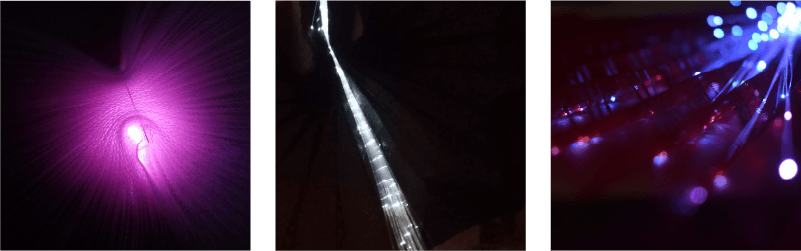
Fiber optic
DESIGNING THE COSTUME
Design process of a wearable
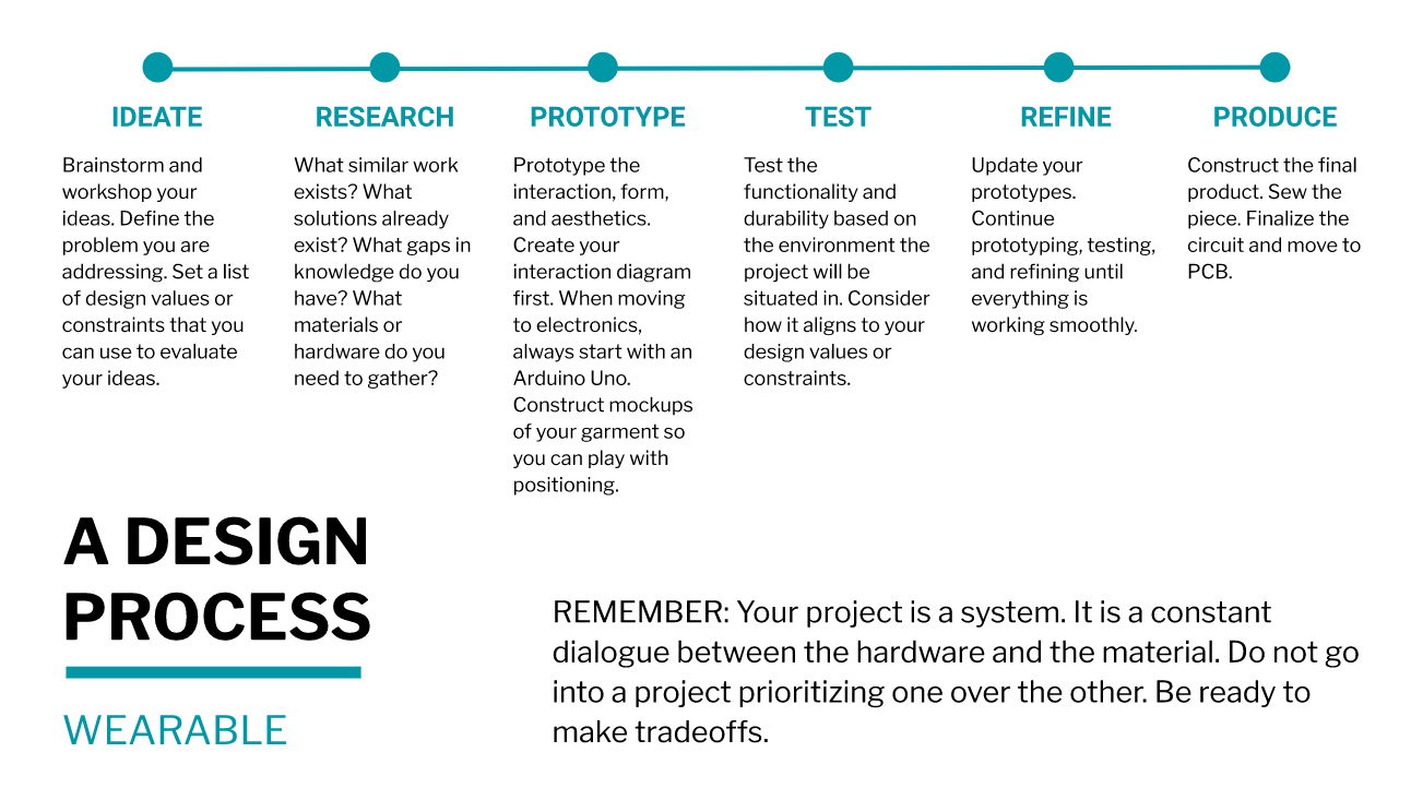
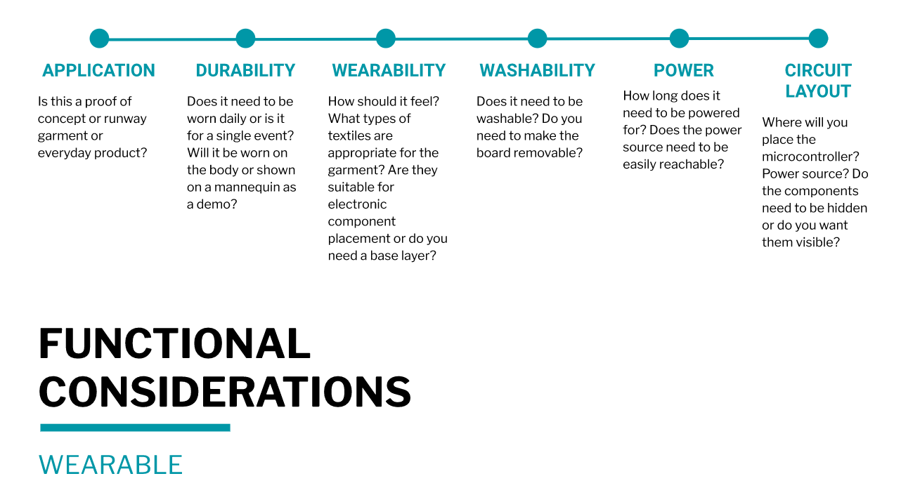 Liza Stark Wearable Class Notes
Sketch

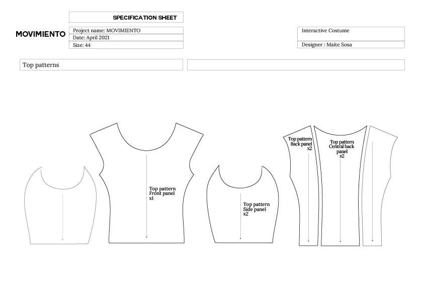
Toile & Pattern Making

Circuit layout
Calculating Power Needs
To calculate the power needs of my project, I found this article called LilyPad Basics: Powering Your Project which was very helpful.
Sensor LSM303 accelerometer Working voltage: 3 V Supply current: 10 mA
Leds and fiber optic I will be using 5 3mm white leds, that need 3V to work and 20mA each to be at max brightness Working voltage: 3 V Supply current: 5x20mA= 100mA
Led firefly string Working voltage: 4.5 V Supply current: 80x2mA= 160mA
In addition to calculating the voltage and amperage each component needs, according to the article, you need to add 10mA for the LilyPad that's running everything
I will need two different power sources, a 3V and 120mA, and a 4.5V and 160mA
As I am working with a large amounts of LEDs, my Lilypad Arduino cannot provide the power I need to feed all my components, so I will need to construct a circuit that will let me use a secondary power source, by integrating a transistor.
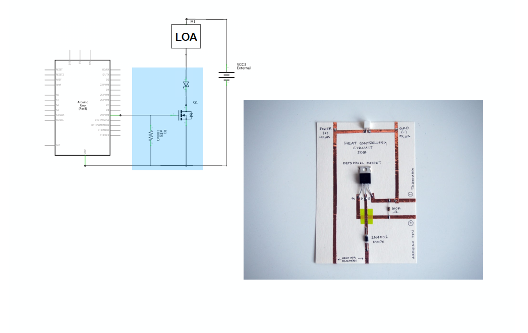
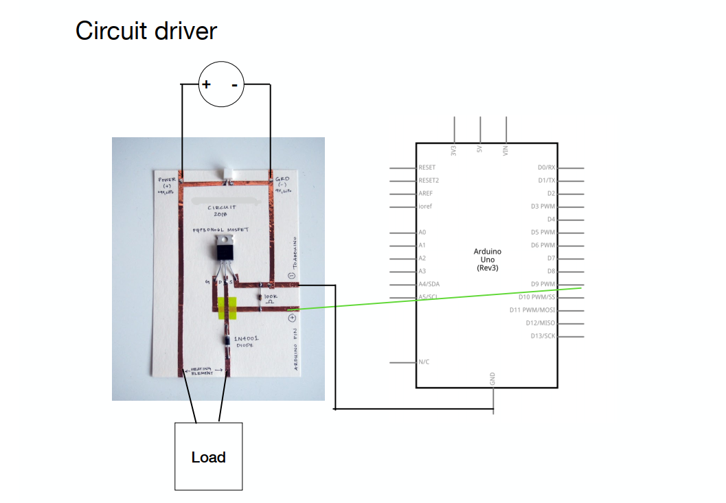
Driver Circuit
A driver circuit is a circuit that allows us to control a Power Load with low voltage (Arduino) but the Current for the Load in sinked by a different source.
In Weareables Week, we learned how to use transistors as an electrical swithc. A transistor is an active component. Its behaviour changes based on the Voltage applied to one pin (Gate). By applying a small amount of voltage to the gate using the lilypad, current can flow between the drain and the source.
![]()
![]()
![]()
 Emma Pareschi Tutorial Notes
In the tutorial Emma recommended we use a N-channel Mosfet - IRLB8721PbF Transistor , but I wasn´t able to get the same in Uruguay. These are the transistors that I was able to get: IRF520, IRFP064 and a QM3006D. I checked each transistor datasheet, and compared the threshhold voltage, as I need a very low threshold voltage max, it has to be less than 2.5V so you can control it directly from a microcontroller running on 3.3V or 5V logic. I finally choose the QM3006D
![]()
Schematics
Process
THE PERFORMANCE
For the making of the performance, I contacted Daniela Olivera, dancer, with whom we explored the expressive possibilities of the costumes in action.
To create both the visuals and the lighting set-up, as well as the recording and shooting of the performance, I worked with Cecilia Mieres, scenic designer, visual artist and friend of mine, with whom I have been working closely for many years.
This process was possible thanks to the help of many people, to whom I am deeply grateful.