5. E-textiles
INSPIRTATION
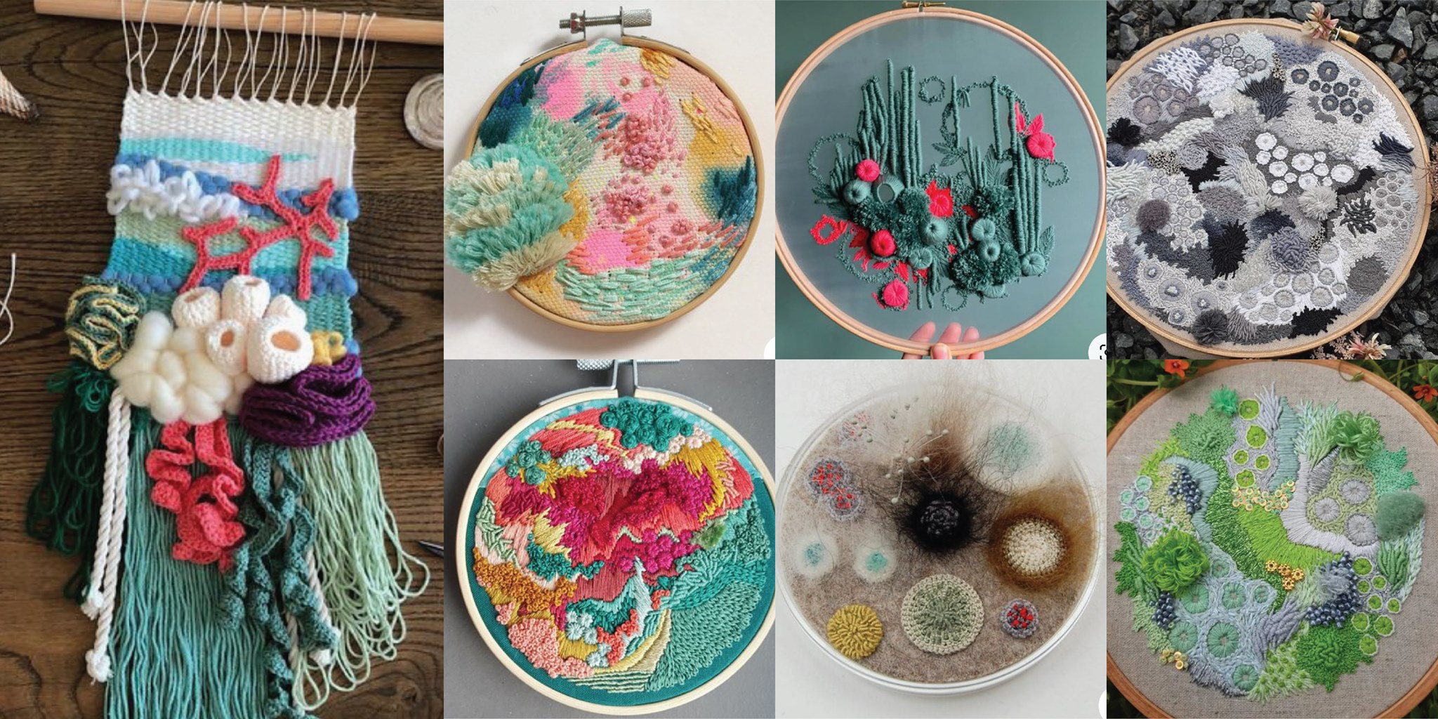
For this assignment I don't have a person or favorite designer that works with e-textiles, I have to confess that I don't know so many, I have to research a little bit more. So, for this time I will post the idea that I want to do. I love this kind of embroidery, like the coral in 3D shapes with different kinds of yarns and threads, I will try to do one like this, but adding some LEDS and ofcorse the digital and the analoge sensor. Let's see how it looks at the end.
GROW?

In this assignment I'm not sure, what can I grow as raw material. Generally the idea is to cultivate some fruit or vegetable that in future I will use for that kind of assignment. For example, last week I grow turmeric, chaya (local mayan plant for green dyes) and Hibiscus flower. But in this ocation I'm not sure what to grow, I would go for cotton, but, I already did, I have one baby plant of cotton; maybe something related with the carbon that is a raw material that is conductive. Let me think more about it...
BASIC ELECTRONIC
Since alway I wanted to have a basic electronics class, I always work with this terms but never ever I had the opportunity to learn from cero. But this time my friend Pablito, the mechatronic engineer from the fab lab maya, is going to explainme from cero, like a "Electronics for dommies" hahaha
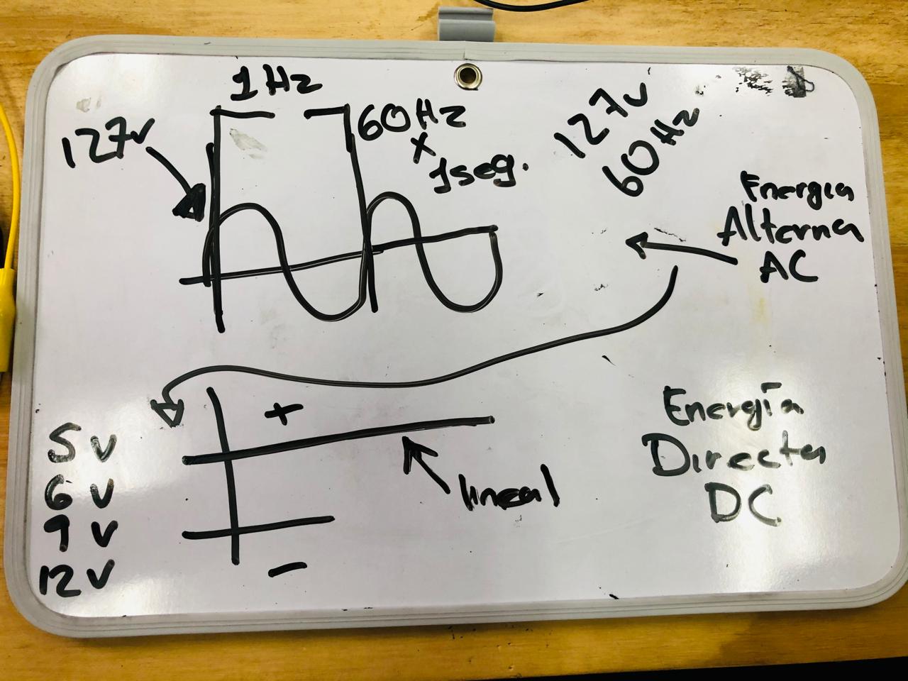
In this board he explain me that there is two different types of energy, alternative energy or AC and Direct energy or DC. Maybe this is fun for you but I've never understood the difference but now I know. The AC is the energy that comes from the plugs and here in Mexico is 120V or 220V it depends and the DC is the one that comes from batteries like 5V or 12V but is less than 120V. For example a computer needs AC that after with a converter it will turno to DC and a Arduino works with DC, when you connect it to the computer, this gives it 5V, I hope it make sense for you.
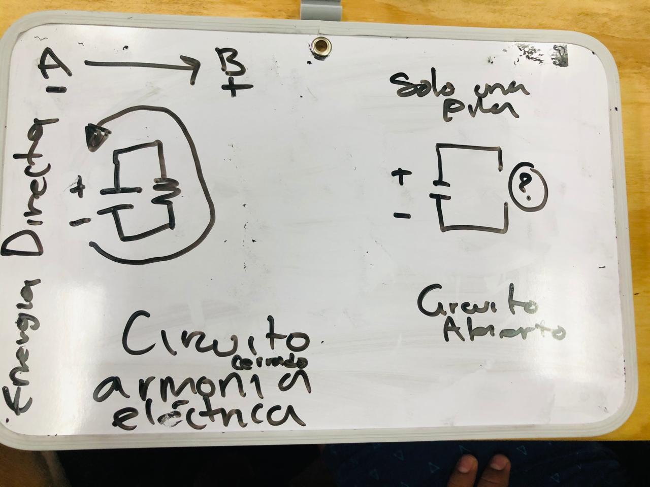
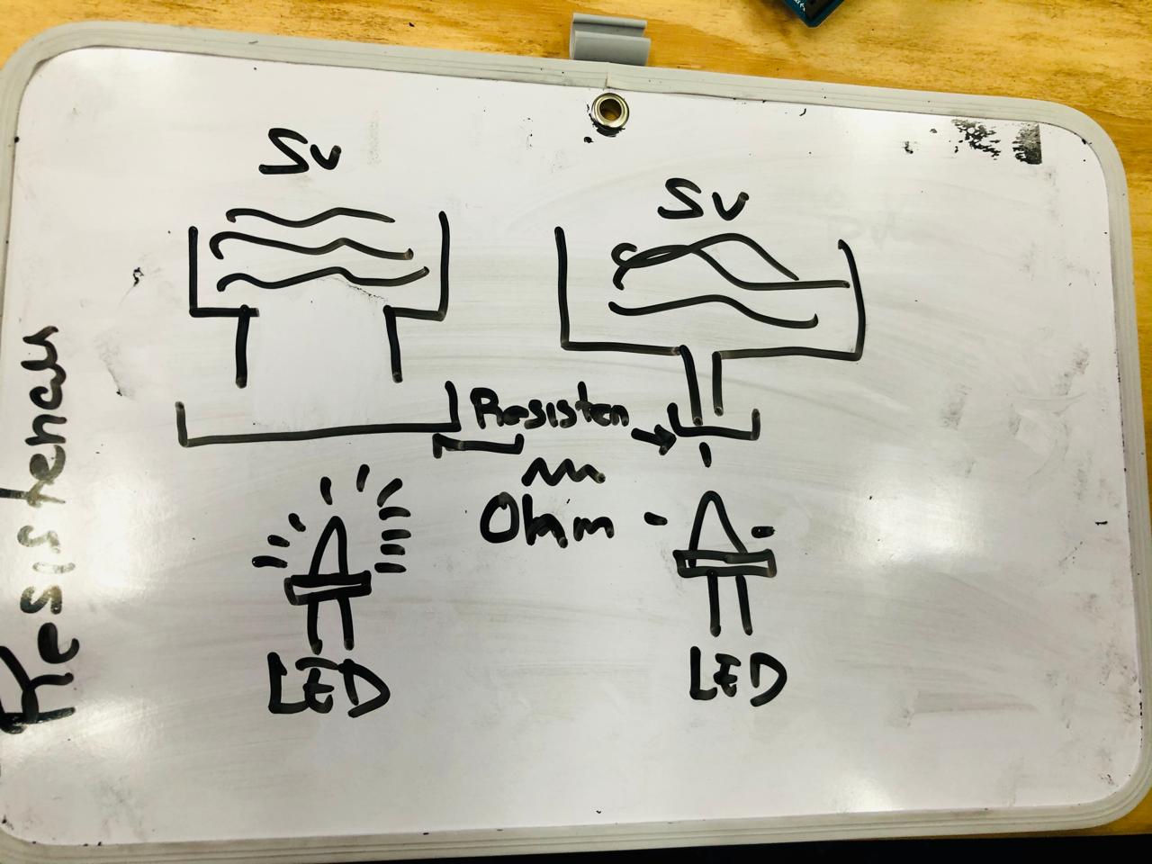
In this Board, Pablito explained me, what the F is a circuit, in few words it is a flow of energy, you need at least energy and a resistance where the energy can flow perfectly. If in the circuit there is something wrong (there is a lot of possibilities that a circuit can be open) it will be open and nothing is going to happen.
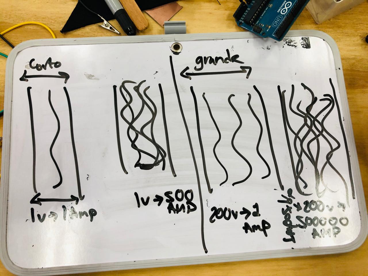
Here we talk about resistances, this little things are like filters, some allowed to flow a lot of energy and others allow a little energy, this can be related with the brightness of the LED, but also, if you use one that gives a lot of energy, the LED will be estress and it will burn sometime.
This is ohm's law equation
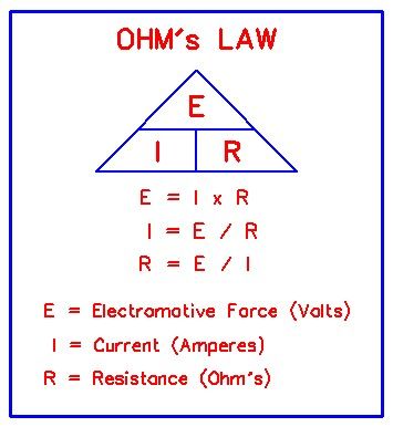
Here we calculated with the Ohm's law formula with Resistance we will need, in this case we have to know the resistance, so we transforma the formula. Ohms law is Electric currence is iqual to voltage between to resistance. But as I said we don't need electric currence, we need to calculate the resistance, so in this case the formula will be like this, Resistance is equal to voltage between electric currence.
Here you have a video for kids from Adafruit that explains Ohms law hahahaha
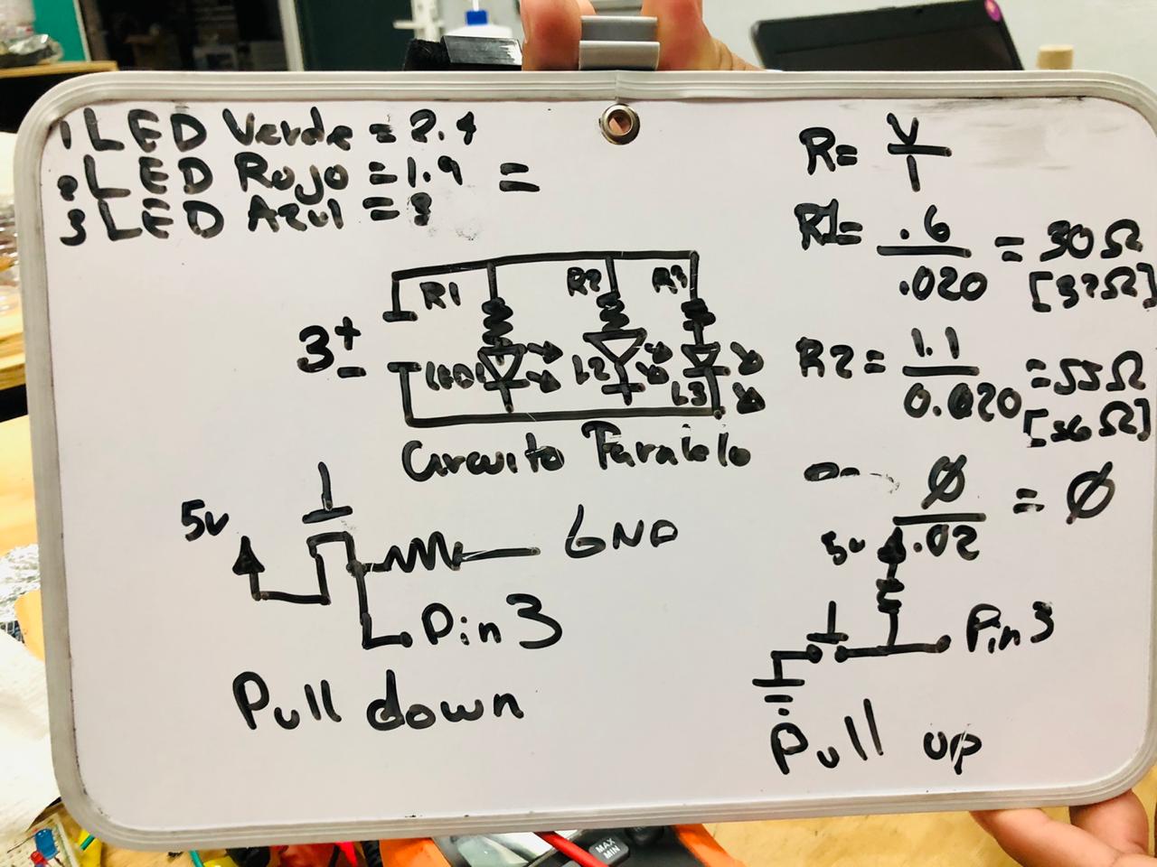
Here we talk about the two differents types of circuit, the parallel circuit and the serie circuit. The thing with the serie circuit is that energy floww for all, one by one, and if one of the elements burn or fail, there won't be energy for the rest, besides the the energy of my 5V battery won¡t be enough. In the paralel circuit the energy goes to all the elements at the same time, so it doen't matter if one fail, the others LEDS will be working.
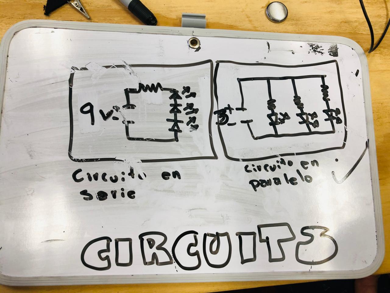
This information is important to get the values of every LED, it help with the operation to get the correct Resistance for every LED depending on their colors.
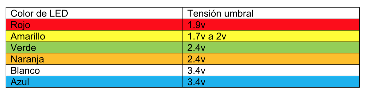
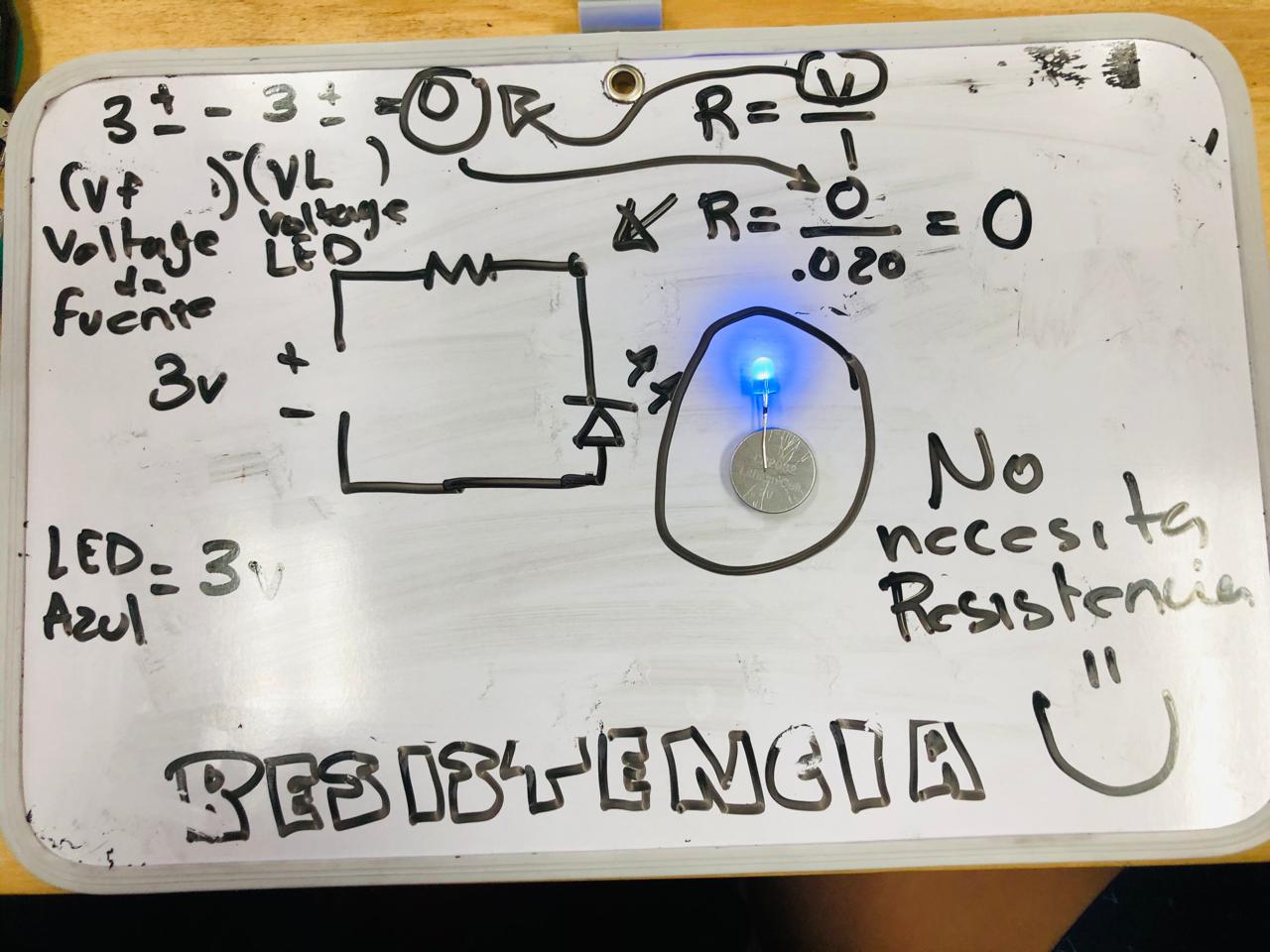
Here in the last board we calculate the resistance that we will need for every LED. I didn't know it but every LED needs different resistances, because they brightness is different, so, depending on this information we need to calculate the ressitance. In this case the green LED needs 32 ohms resistance, the red LED needs 35 ohms resistance and the blue one dosn't need resistence, that why when we connected directly to the battery, it doesn't burn, because it works with 3V and battery is 3V.
I hope this explanation make sense for you. THANK YOU PABLO!<3
THE ASSIGNMENT
This assignment is about working with Arduino, the first time i did it, it was while I was studying my master in IAAC, it was for a smart facade, so I'm very familiar with its interface. So working with this we will need to understand two things, the hardware and the software that I will explain later. For this assignment I decided to work with the Attiny85 because I know how to do basic circuit, and I like to impurve my skills even it is not necesary for this assignment, besides, I saw studens from the past years that they do the same. I hope it works.
COMPONENTS FOR THIS ASSIGNMENT
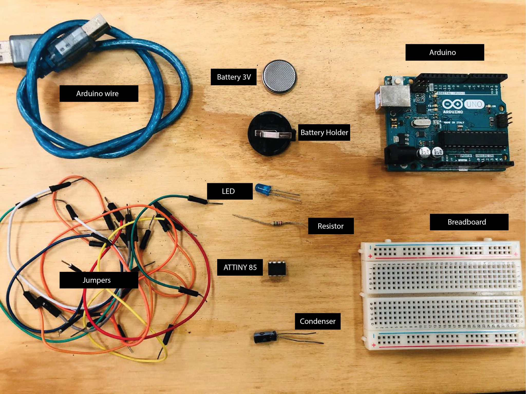
For hardware I will need basic things, Arduino Uno is the best for start, there is tons of information and video tutorials on internet about how to used it, really, tons of information, ofcouse with its own wire that conect it with the computer. Also we will need a breadboard, this is for connecting all the elements of our circuits, the breadboard will need a lot of jumpers, male and famele and combined. A 5V battery with its Battery holder, its better to have more because in the way batteries will run out of energy. The LEDS with the colors you like the most. The attiny works with 5 pins so maximun you cn conect 5 LEDS but we will need a button, so I will use four LEDS and one button. The Attiny 85, i bought more in case I burn one and a condenser that this will help to progamme the attiny so we only will use it one time.
DATA SHEET ATTINY85
Always always always we have to work with data sheet, it helps a lot, it something I learned during my Fab Academy. Here you can see the Data sheet of the Attiny85. As you can see it has 8 pins, number one is reset, this one you will only programmed once in the arduino. Usually the attiny85 came with nothing like in blank, so the first step is to say it like "Hello, you are going to be programmed with an Arduino Uno. The pin 2 and 3 are digital pins, this mean that we can send data from here to a LED or button or another electronic component. Pin 4 is GND, here we have to conect the negative energy.
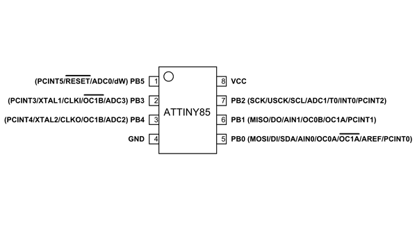
In the other side, the 5, 6 and 7 PIN are other digital Pins, the same as Pin 2 and 3. And the 8 Pin is the VCC, it means here we have to connect the positive energy.
PROGRAMMING ATTINY 85 WITH ARDUINO
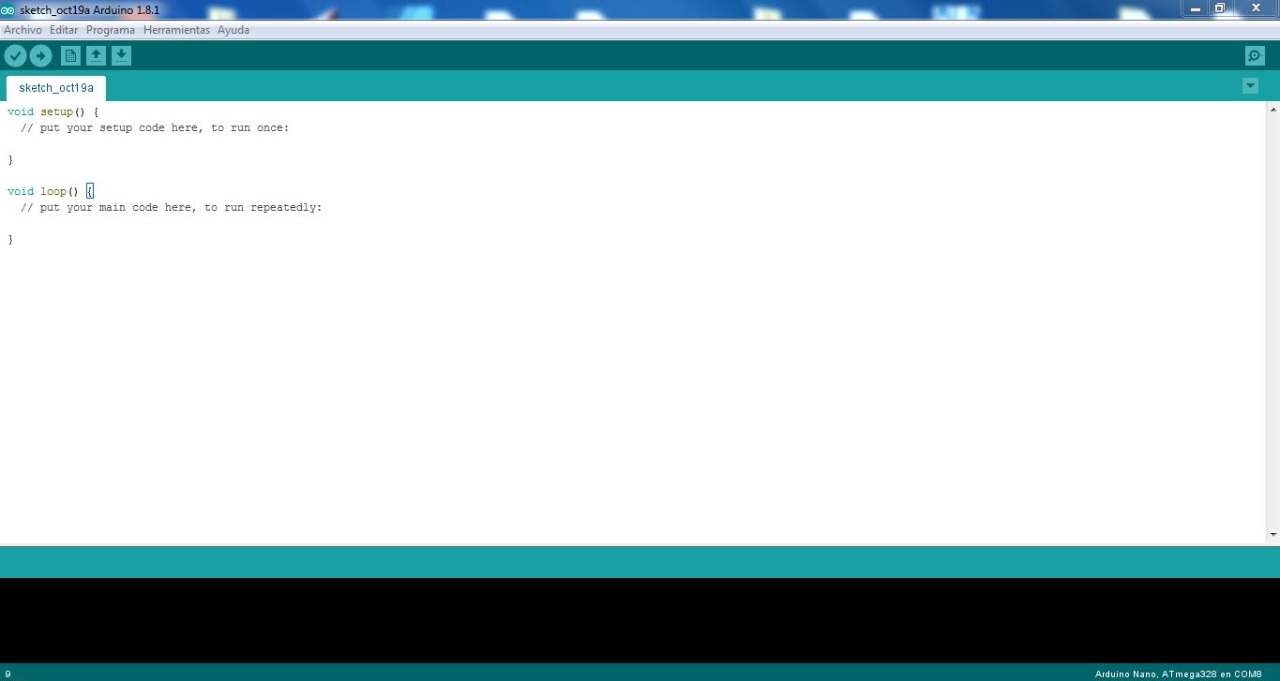
First of all this is the Software, make sure you have the latest version, i had a old one, and when I was trying to program the attiny85 it didn't work until I download the latest version.
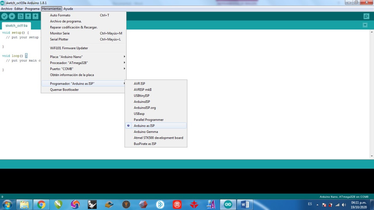
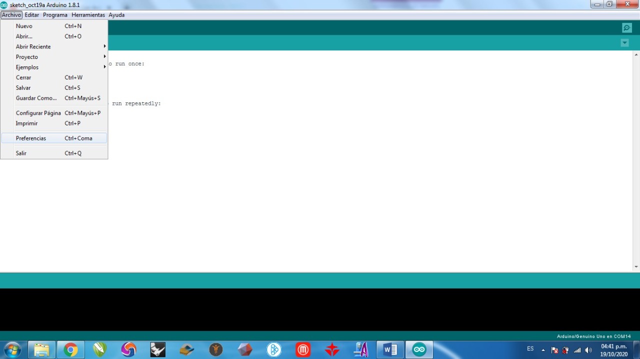
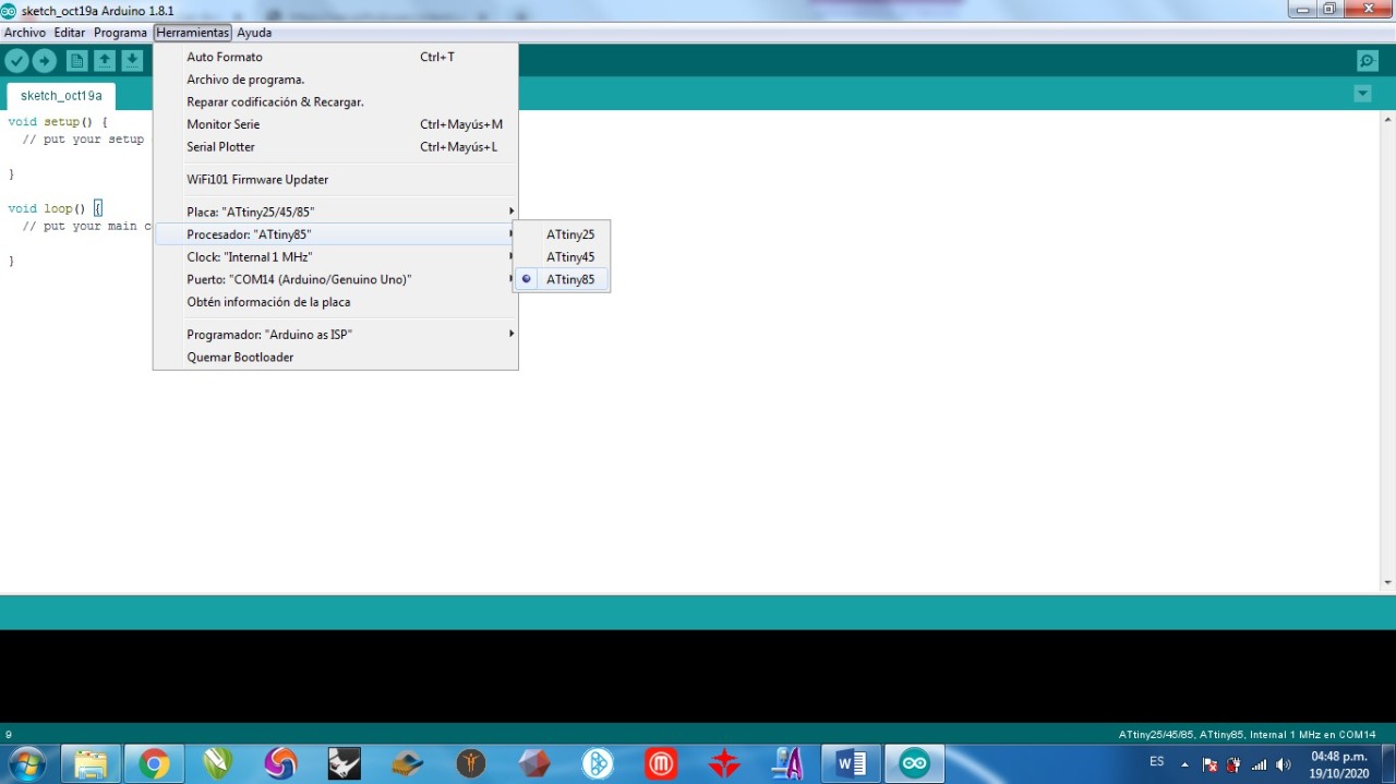
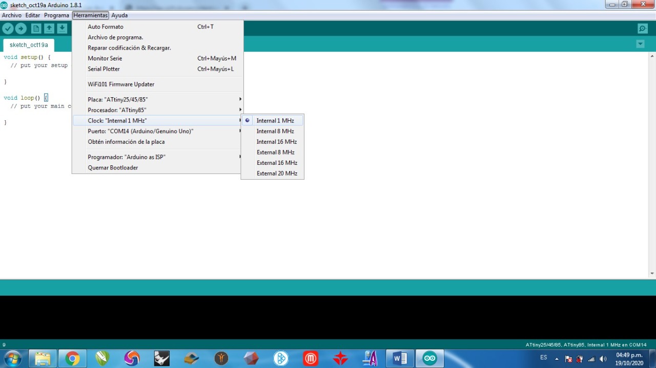
For programming the attiny85, the first step is to say to the software Arduino that It will programe the attiny, so, forst we have to tell it in the option "Herramientas" ot "Tools", then select the option "Programmer" and then select the "Arduino AS ISP" option.
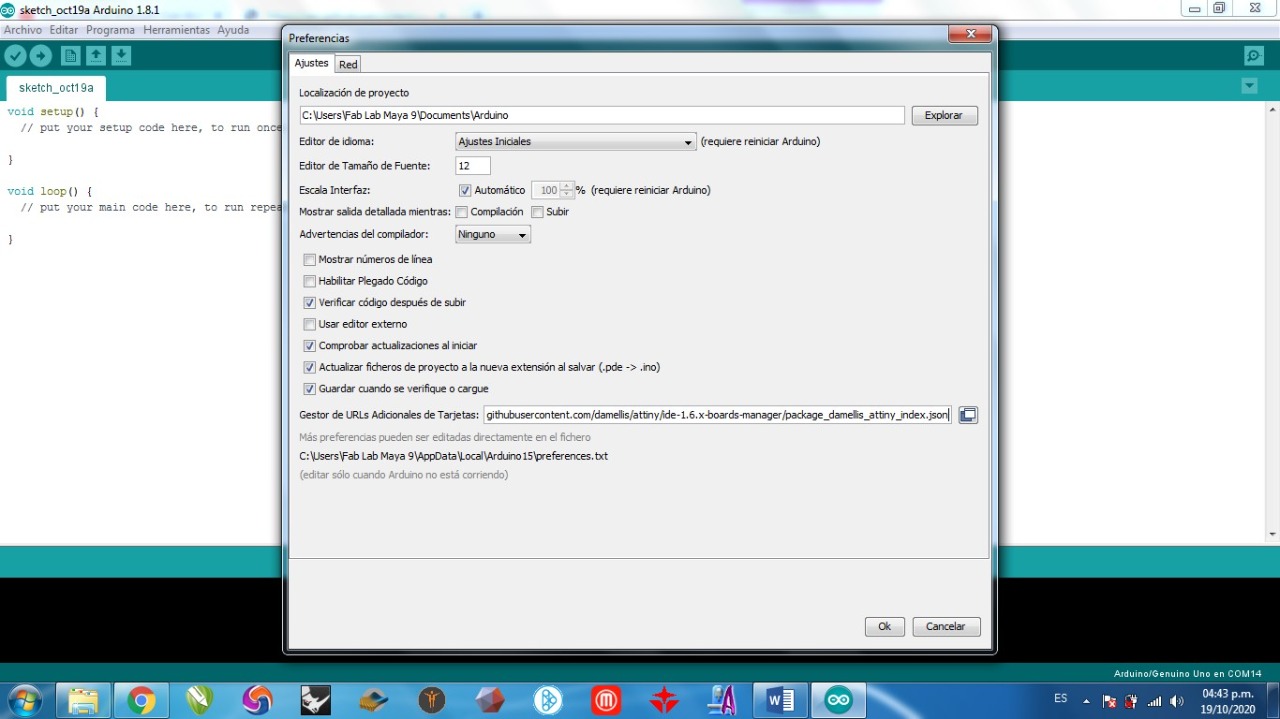
Here you have to go to "File", then select "Preferences" in this pop up window you have co copy this link "https://raw.githubusercontent.com/damellis/attiny/ide-
1.6.x-boards-manager/package_damellis_attiny_index.json" in the option "Gestor de URL adionales de trajetas"
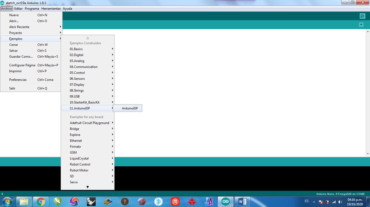
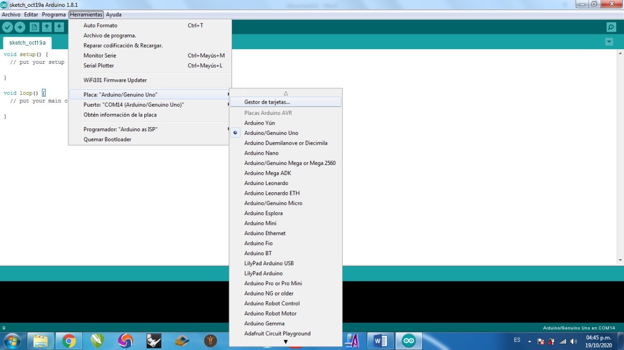
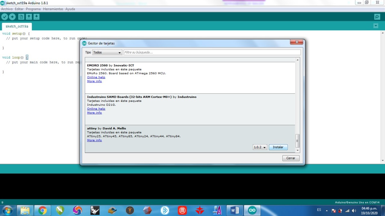
After this you have to go to the "Gestor de Tarjetas" and it will appear a pop up window where you have to install the plugin specific for using the Attiny85. This is a most, otherwise it won't work.

I followed this fritzing that i found on internet. This is the way you have to connect every component in the real world to program the Attiny85.
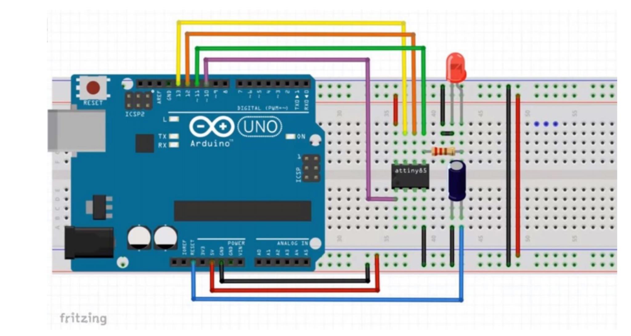
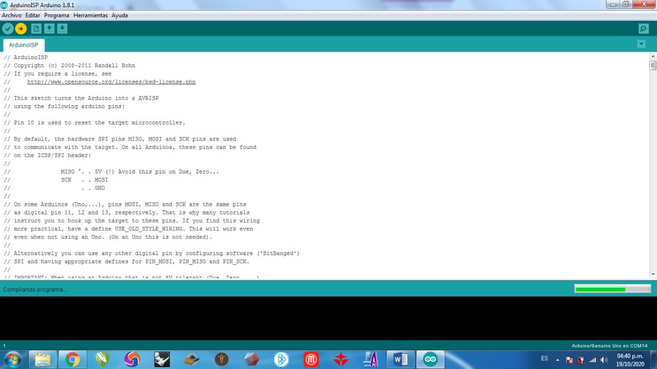
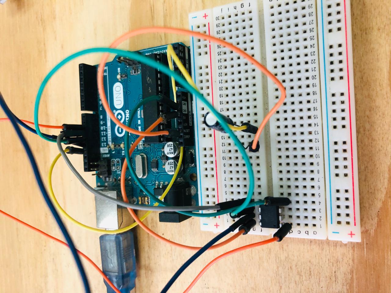
Here is exactly the same as the fritzing, I connect it to the computer I run the code and that's it, there you have it. Now we can program the attiny for different purposes and with differents components.
Here in the video you can see the way I programmed, to light up all the LEDS in a very fast way.
PROGRAMMING ATTINY 85 from Trinidad Machuca on Vimeo.
DIY CONDUCTIVE FABRIC
It didn't get on time the fabric for this assignment. Here in Mexico there is no one that can sell fabric, only thread and not for the digital embroidery machine, only for manual sewing. The only way is to buy it from USA, but I have bad luck, because something happened that is in the customs ans I have to pay taxes, etc. So I will have fun making my own DIY fabric.
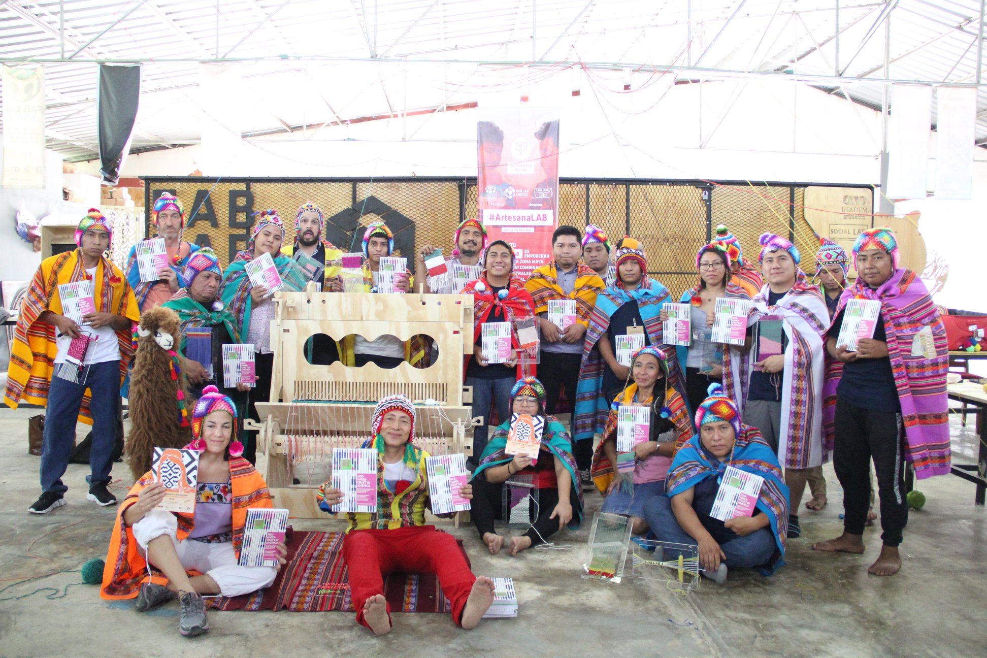
My lovely tutor Adriana Cabrera recomend me this link, and that reminded me the my very famouse fab lab friend, Walter Gonzales has a a project called "Fab Loom", he is from Perú and he invet a lot of ways to fabricate the loom in the laser cutter machine and in the CNC machine for making your own textile, so, I had the idea to use the mini loom for making conductive fabric, that we fabricated when he came to the Fab Lab Maya.
Here is Walter in the Fab Lab Maya after we finished his workshop with the Fab Loom <3 in the middle of the COVID-19
I will try two optional ways to make conductive fabric, first is the one that I mentioned that I will make with the Fab Loom and the second is with conductive ink. Lets see wich one is better.
FAB LOOM FABRIC WITH THREAD
This is the Fab Loom, I have to put threads in two ways, one in vertical way and also in the opposite way. Conductive thread is a bit expensive, so in the Vertical I will use cotton that is not conductive and in the other way I will use conductive thread.
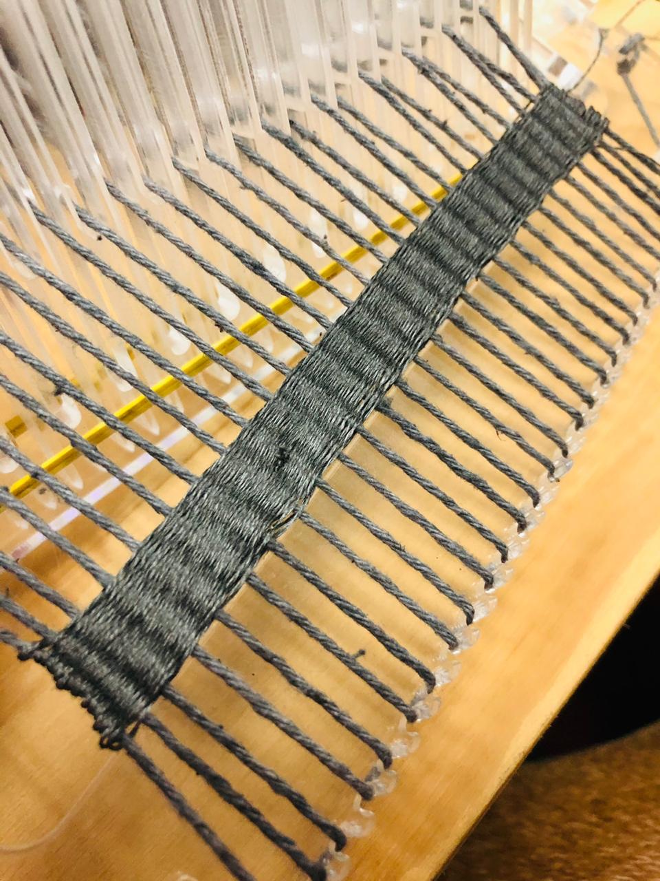
ITS WORKING!
tela conductiva telar walter from Trinidad Machuca on Vimeo.
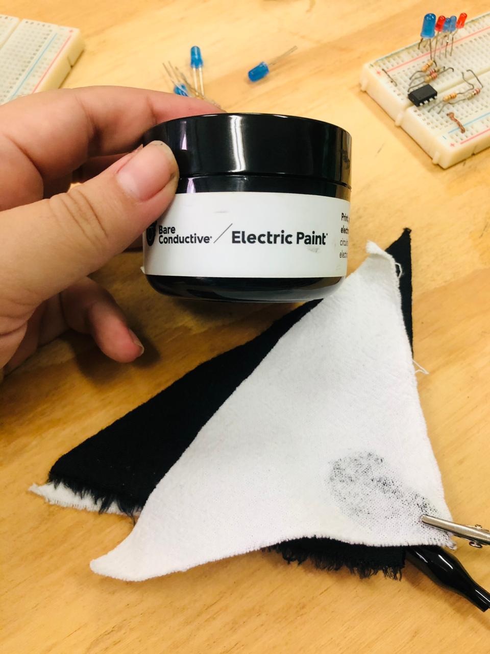
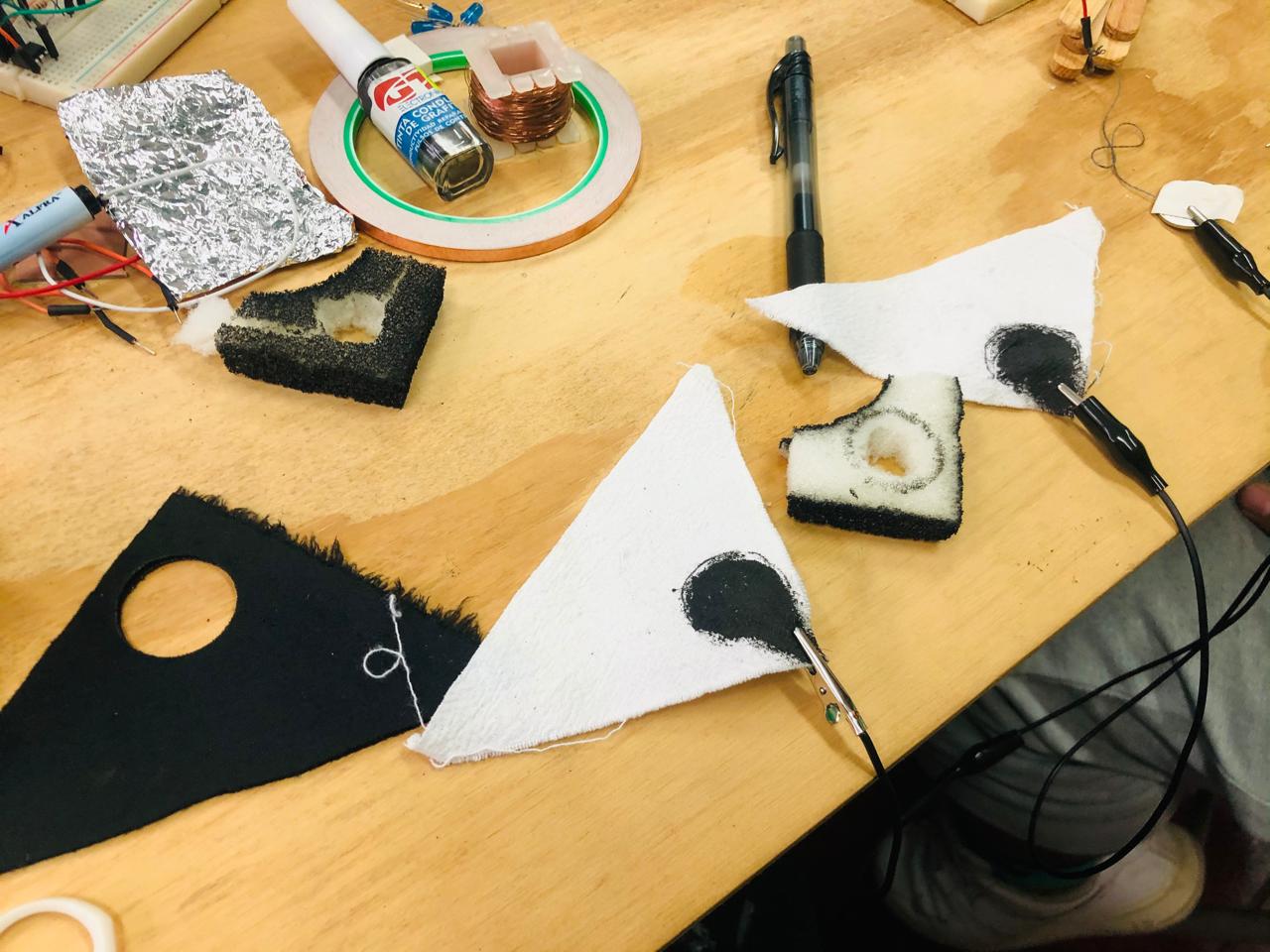
FABRIC WITH CONDUCTIVE INK
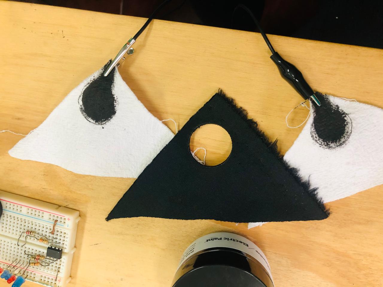
Other option that I have is to use my conductive ink, this is a dirty experiment, where I only painted a little area in two pieces of normal fabric, in between I used a foam, and I will used like a button, so when they touched each other they will turn on my LEDS.
SOFT DIGITAL SENSOR
Here you can see the three layers of the button, I try with the voltmeter and it works, no so well as I expected but it is working.
Here is the Arduino code that i will use to turn on four LEDS with one soft button.
// the setup function runs once when you press reset or power the board

int LED_BUILTIN = 0;
int LED2 = 1;
int LED3 = 2;
int LED4 = 4;

const int BTRINI = 3; //BOTON


void setup() {
  // initialize digital pin LED_BUILTIN as an output.
  pinMode(LED_BUILTIN, OUTPUT);
  pinMode(LED2, OUTPUT);
  pinMode(LED3, OUTPUT);
  pinMode(LED4, OUTPUT);

  pinMode(BTRINI, INPUT);

}

// the loop function runs over and over again forever

int VALOR_BTRINI = 0;


void loop() {


VALOR_BTRINI = digitalRead(BTRINI);

if (VALOR_BTRINI == HIGH) {
    // turn LED on:
    digitalWrite(LED_BUILTIN, HIGH);
    digitalWrite(LED2, HIGH);
    digitalWrite(LED3, HIGH);
    digitalWrite(LED4, HIGH);
  } else {
    // turn LED off:
    digitalWrite(LED_BUILTIN, LOW);
    digitalWrite(LED2, LOW);
    digitalWrite(LED3, LOW);
    digitalWrite(LED4, LOW);
  }
  }
Here you can see how I'm reading the values of the analog sensor
Analog reading from Trinidad Machuca on Vimeo.
SOFT ANALOG SENSOR
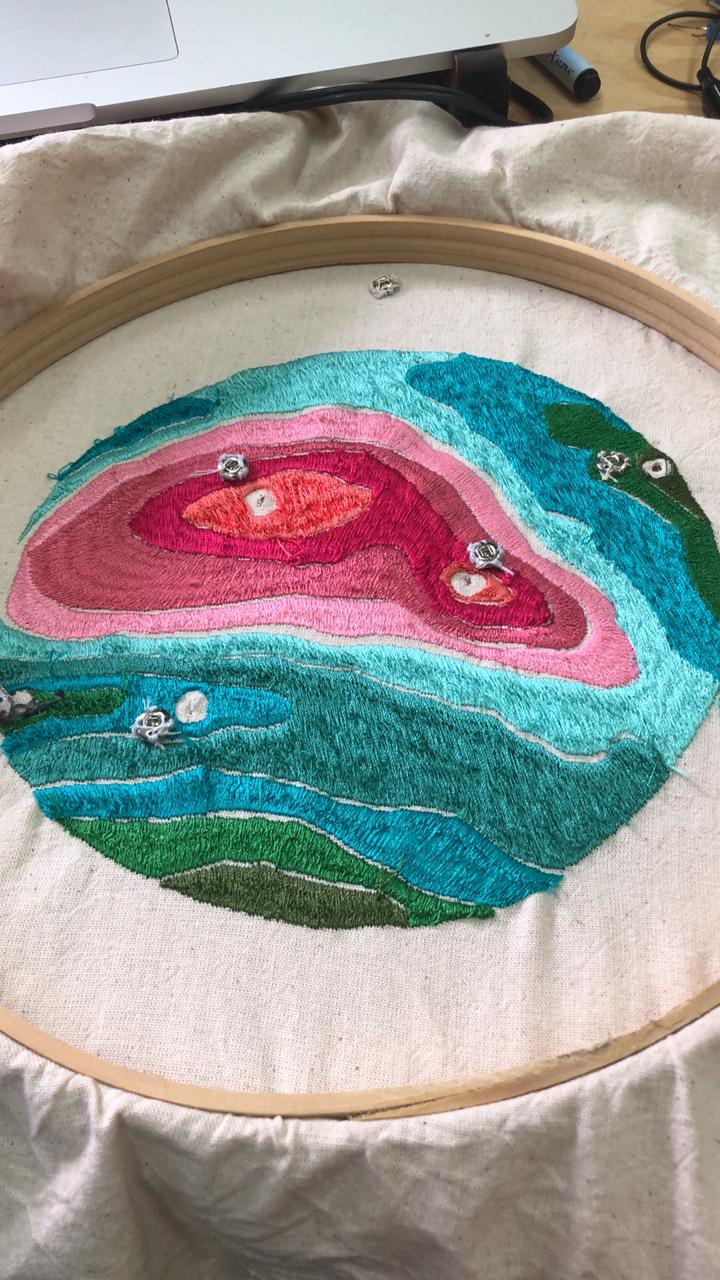
for my analog sensor, I sew a little part with conductive thread in my embroidery frame, The idea is that, when I touch this part of the embroidery the LEDS turn on. In the under part I let a pin, where I can conected to the attiny pin or directly to the arduino.
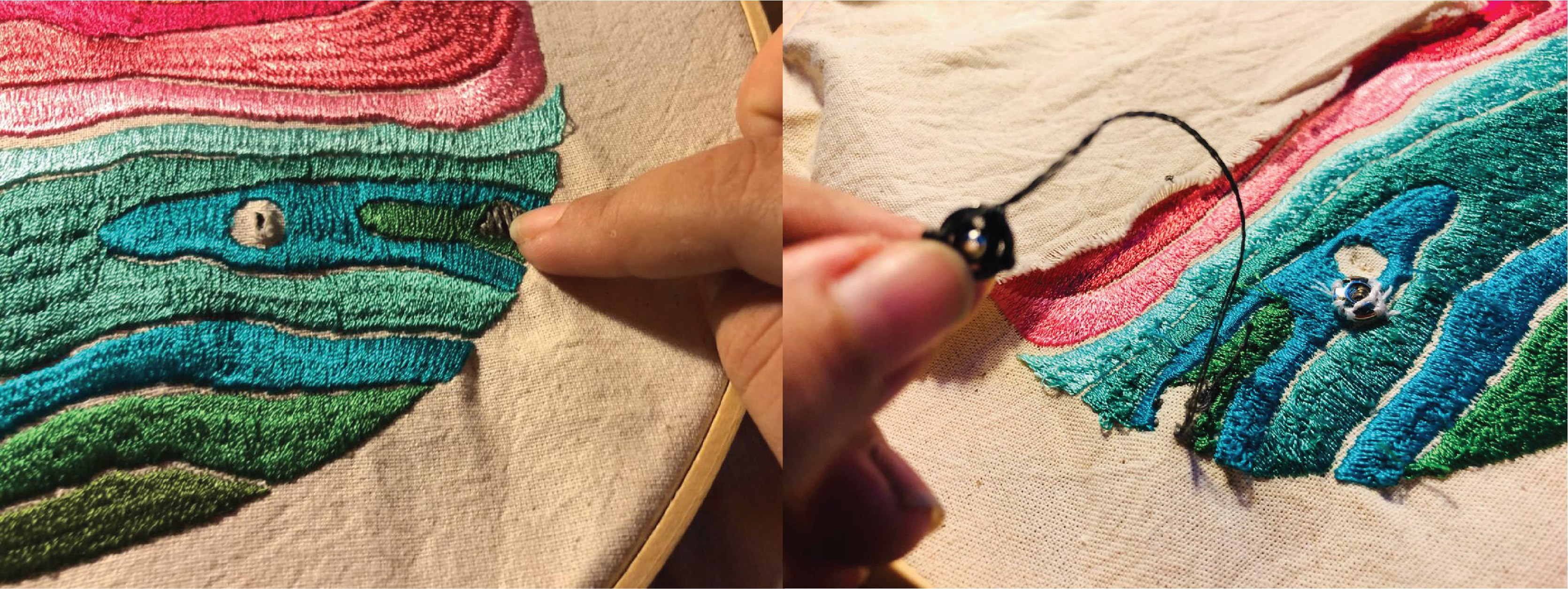
As you can see is working!
Capacitive sensor from Trinidad Machuca on Vimeo.
Here i'm reading the values with the serial monitor.
DIGITAL EMBROIDEY MACHINE
Before starting sewing the circuit I had the idea to make other two kind os sewing, one is the manual circuit, other is manually embroidering and I wanted to use the digital embroidery. I would have loved to embroider the circuit with the conductuve tread but as I mentiones before my thread is only for manual sewing. Once, I tried to used it and it easily breaks.
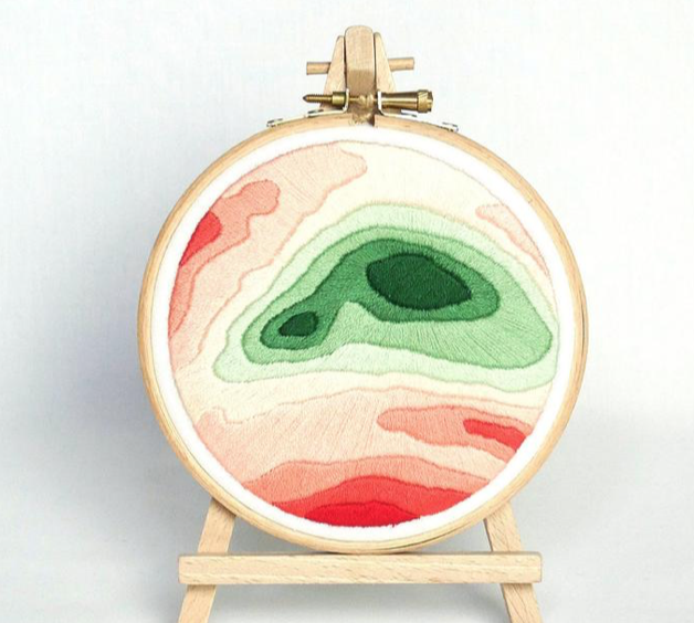
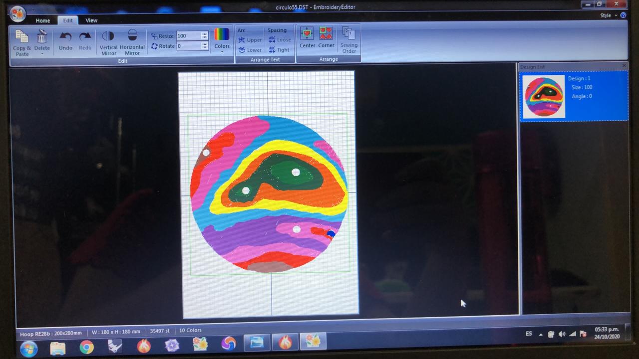
As I mentioned before, I wanted to do a coral embroidery, so I found on internet this that for me it looks like the water and it will be look cool with the 3d forms or the corals.
I imported this image in the embroidery's machine software to trace the image into a vectors. I tried first making the draw in Rhinoceros 3D but when I imported to this software it was a mess, so at the end I decided to draw everything since the beggining.
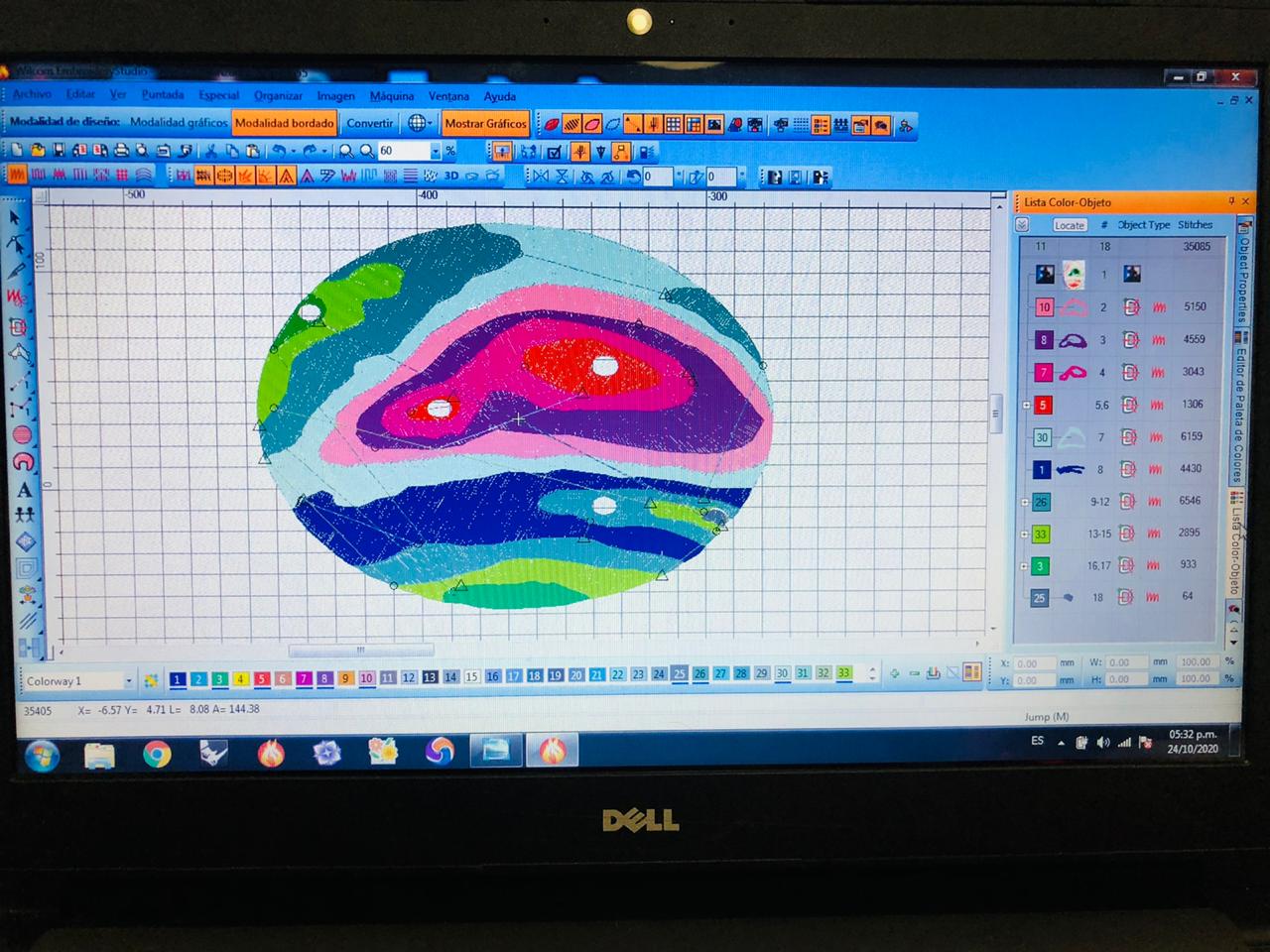
After this step I imported it into an other software, the one that is in charged to make the G-Code. Here I have to tell what size of frame I will use and what colors I will use, so the machine knows when to stop to change the threads.
This is my baby, I love it and I hate it at the same time, because is one of my favorites machines in the Lab but lately gives a lot of problems, it feels that it doesn't want to work with me hahahaha. I have to call Mike, that he is very patien with the machines and he can fixed it very easily. It took almost one day to do this becuase all the problems with the machine but it worth it. Thank you Mike by the way.
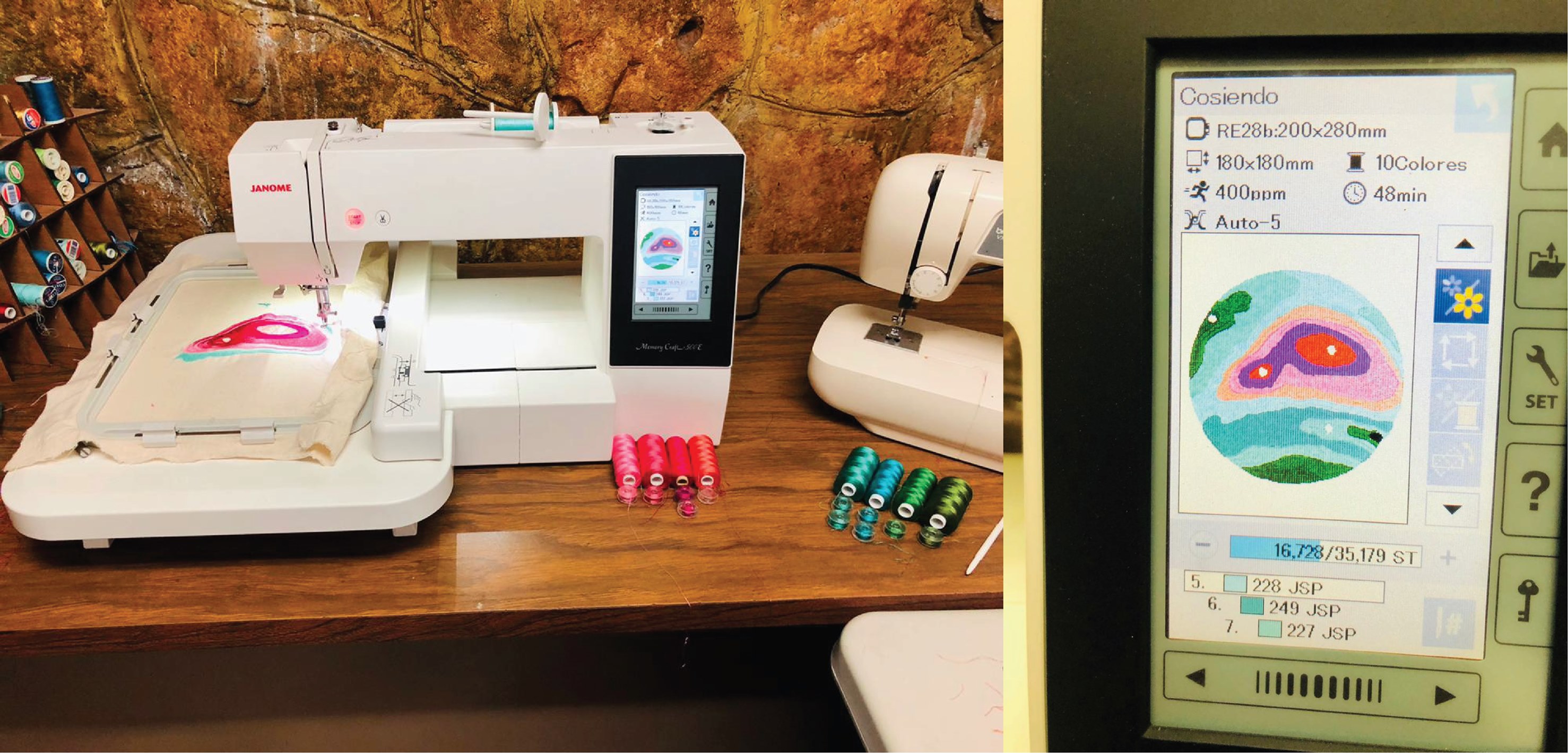
Here you can see my janome embroidery machine working with my design. It looks beautiful to me hahahaha.
Embroidery machine from Trinidad Machuca on Vimeo.
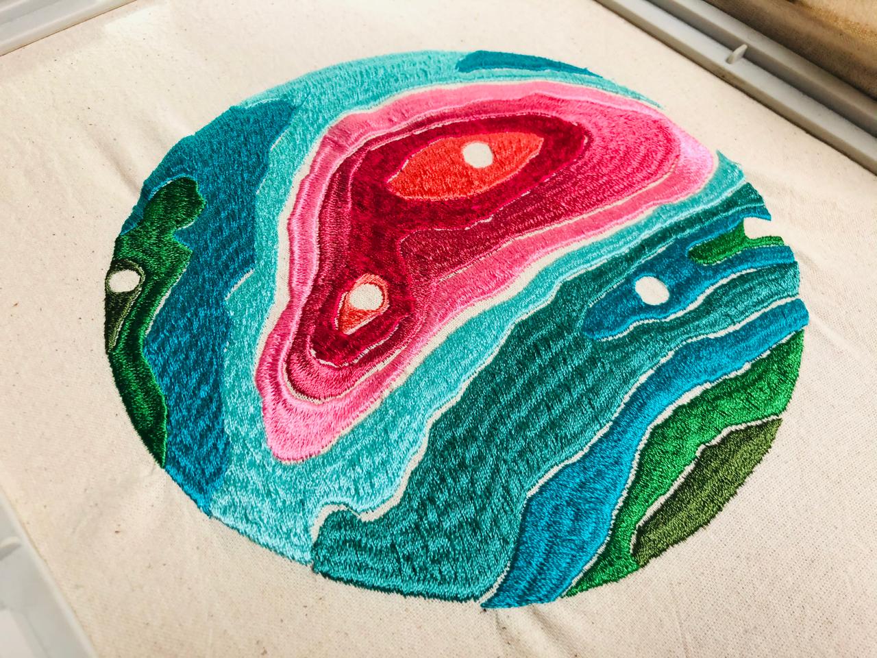
And here is the final result, as you can see, there is a with holes, this spaces are like this because here I will cut the fabric and I will put some LEDS. I really hope that works.
HANDMADE EMBROIDERY
CIRCUIT EMBROIDERING
Here I'm in my apartment on sunday where I'm going to finish to sewing the soft circuit. Here is my workspace with all my important stuff that I will use. It is not clear in the picture but in the computer I had my schematic circuit to follow for the embroiderig part.
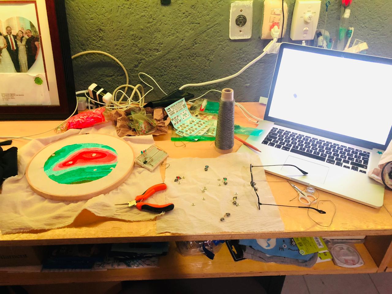
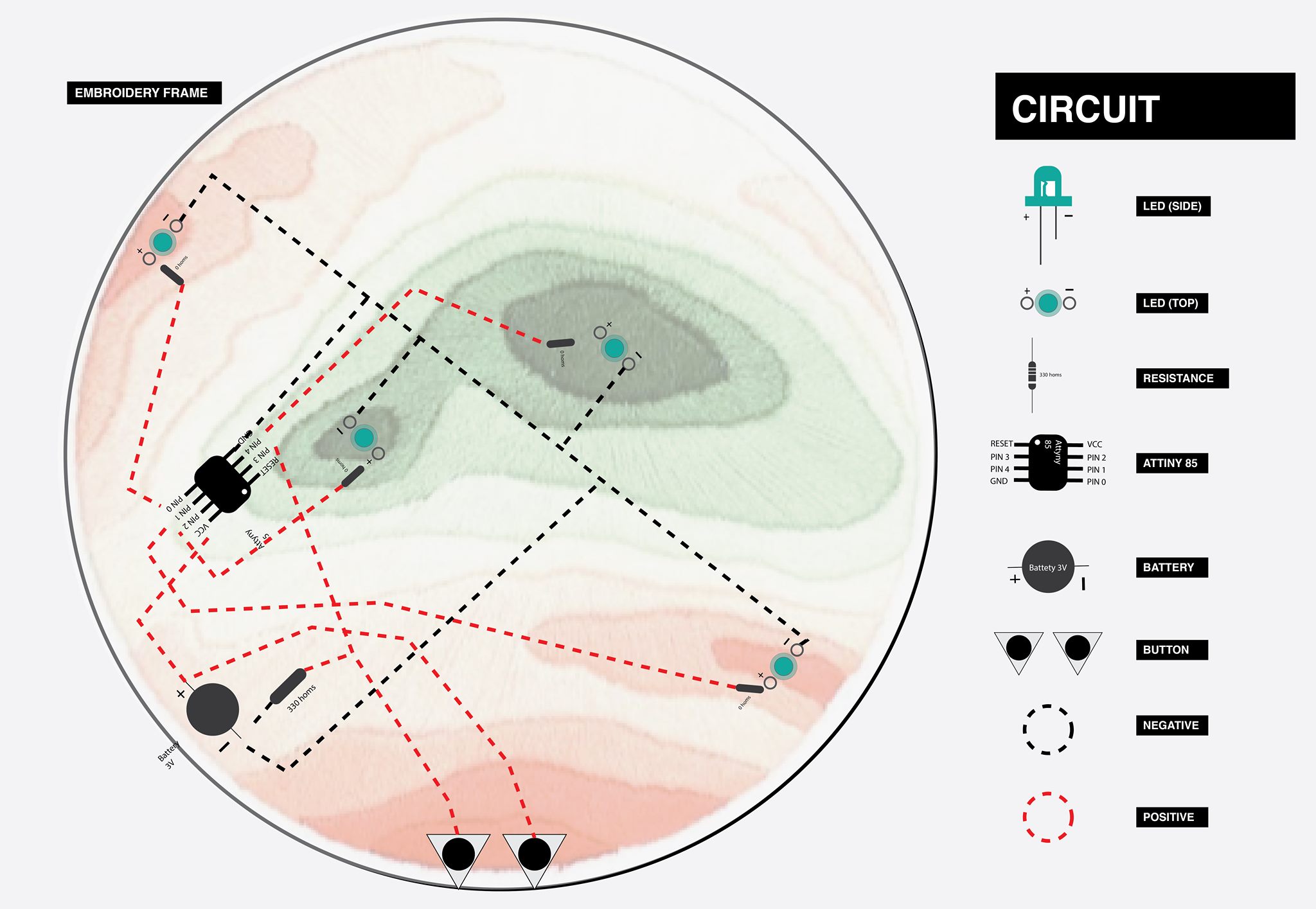
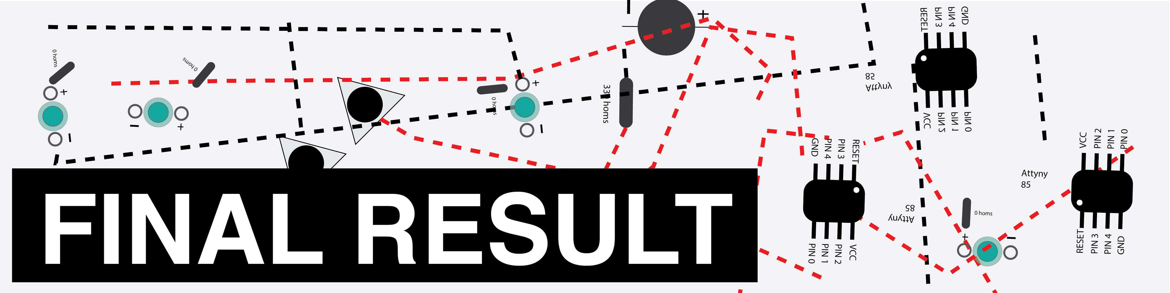
This is my electronic schematic that I will followed in the real world hahaha. Here i have with all the component that i will use, the resistances, the attiny85, everything.
Always when I do workshop of soft circuits or e-textiles, I make this kind of images, do the assistants can understand a little bit better, even for me, it helps me to understand it more.
First I wove the buttons.
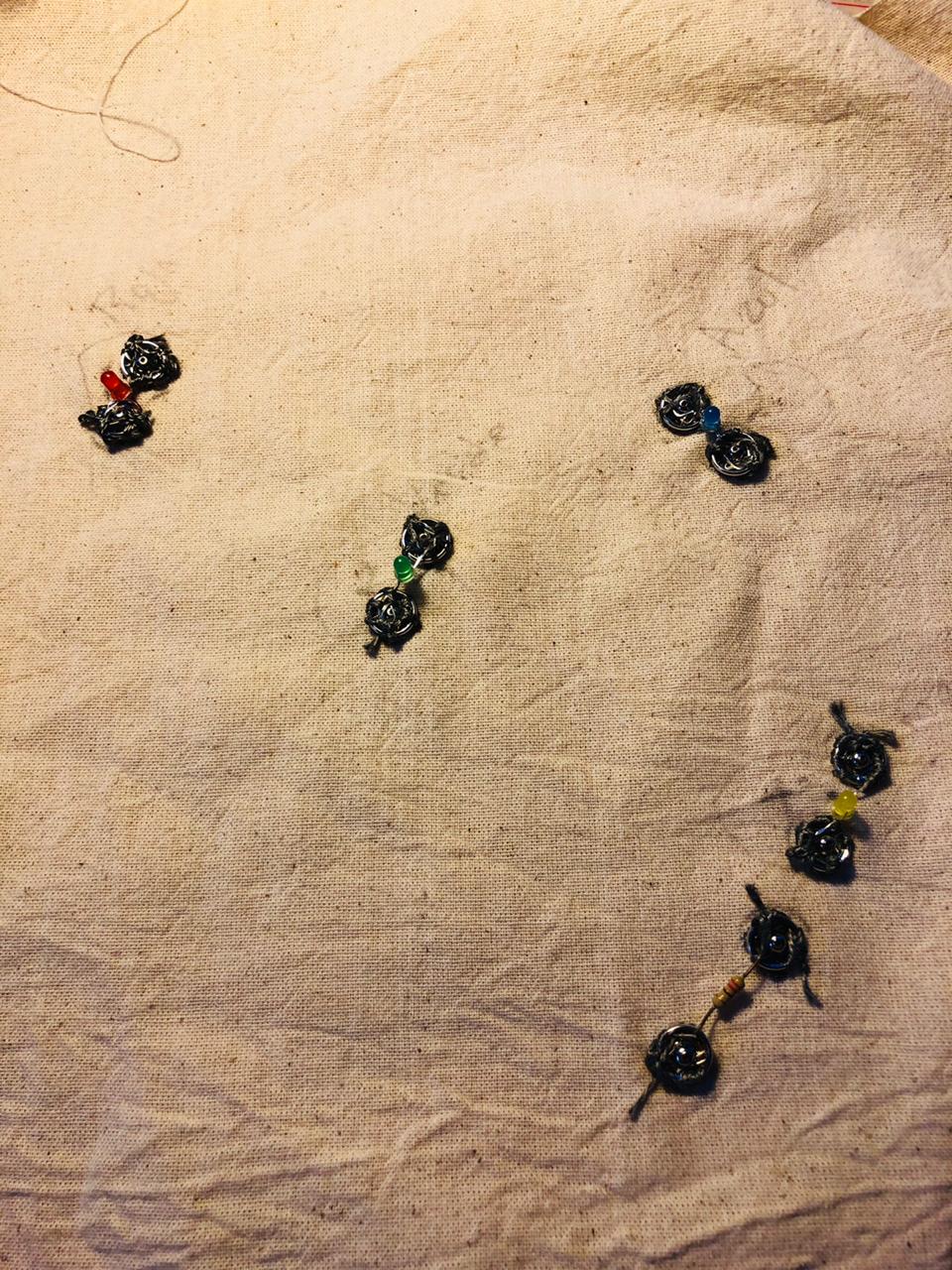
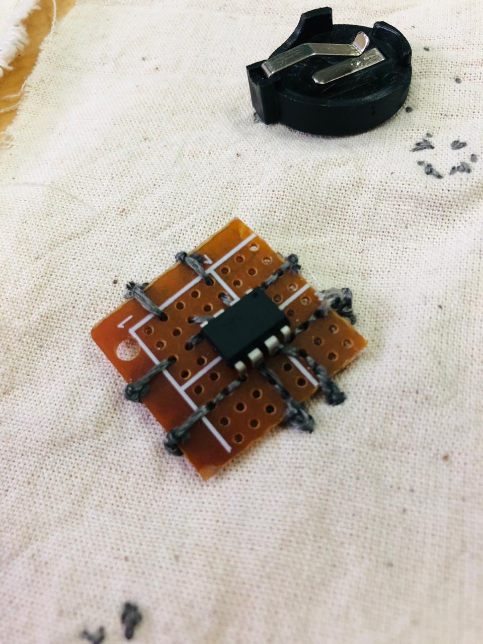
I attached the LEDS in this metallic pins in the case I burned some of the components, I did the same with almost everything or at least the LEDS and the Resistances. It took me a lot of time, more than It will take it if I would sew the components directly in the fabric but I'm very sure this will be better in future.
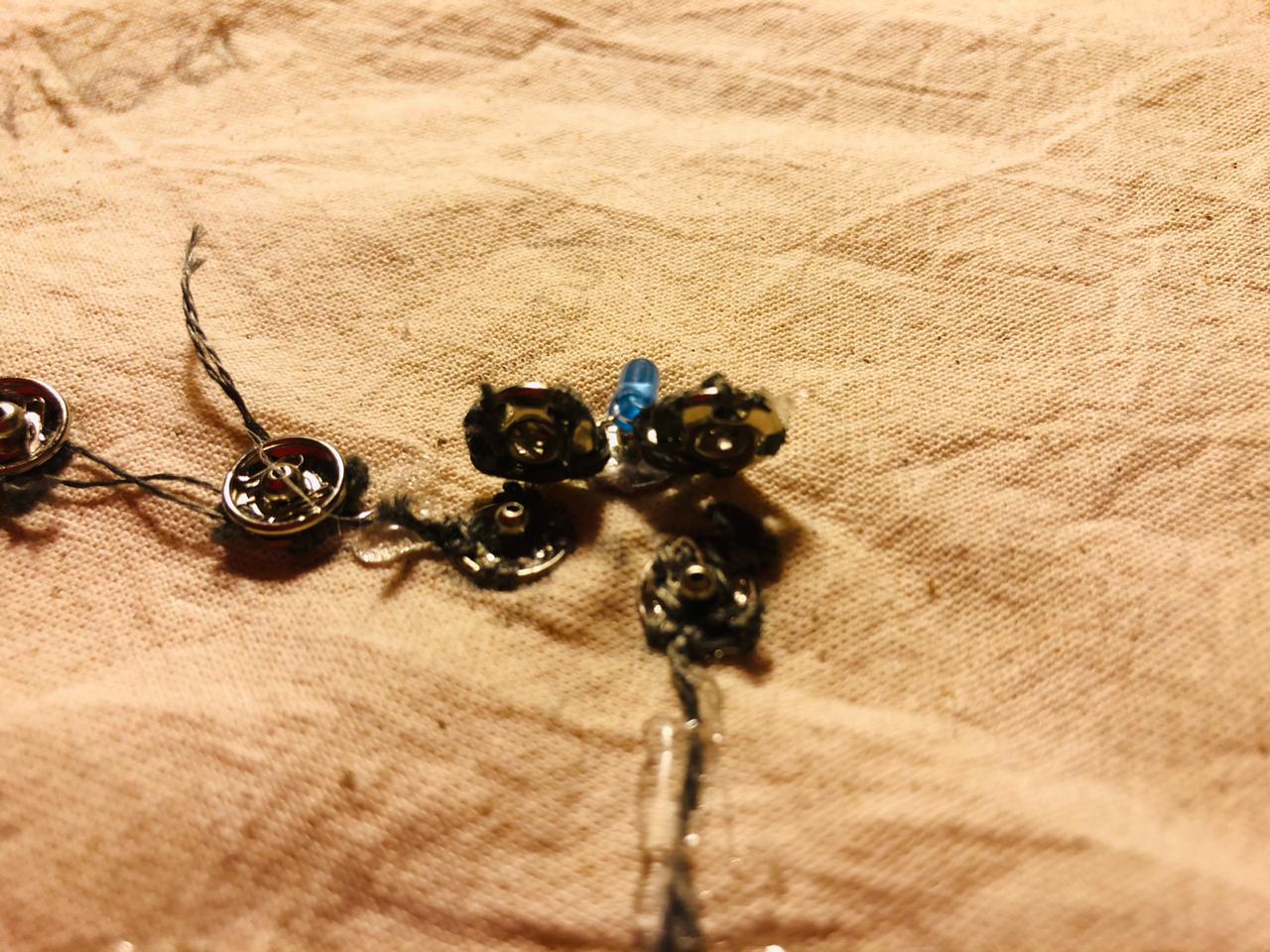
Then i attached my digital button that I made before under my frame, so in the embroidery part I can push and this is going to react.
One of the most difficult parts is to sew the Attiny, the pins are so little that if they touch each other it won't work, that is why every time I finished to sew a pin, I insulate the conductive line. It was hard honestly but with the practice I finished fast hahaha.
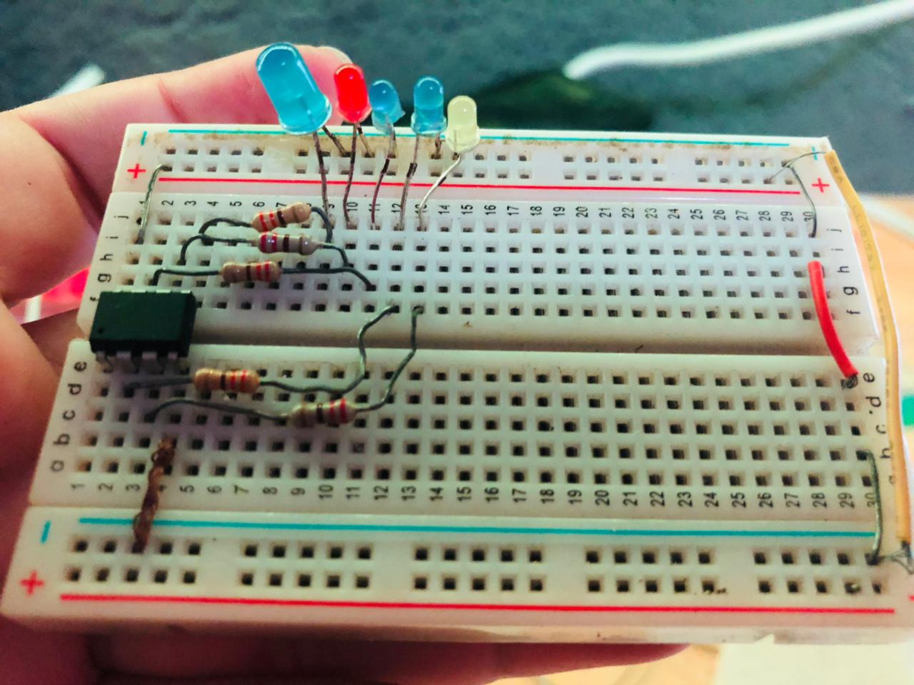
Here I have almost all the components of my circuit, so every time I have to sew them, I took some of them that were before in the arduino. Always before to sew the soft circuit, you have to programmed in the Arduino.
You need to do this to verify your circuit other wise if it is not working it will be harder to fixed with the soft circuit than moving all with the jumper wires.
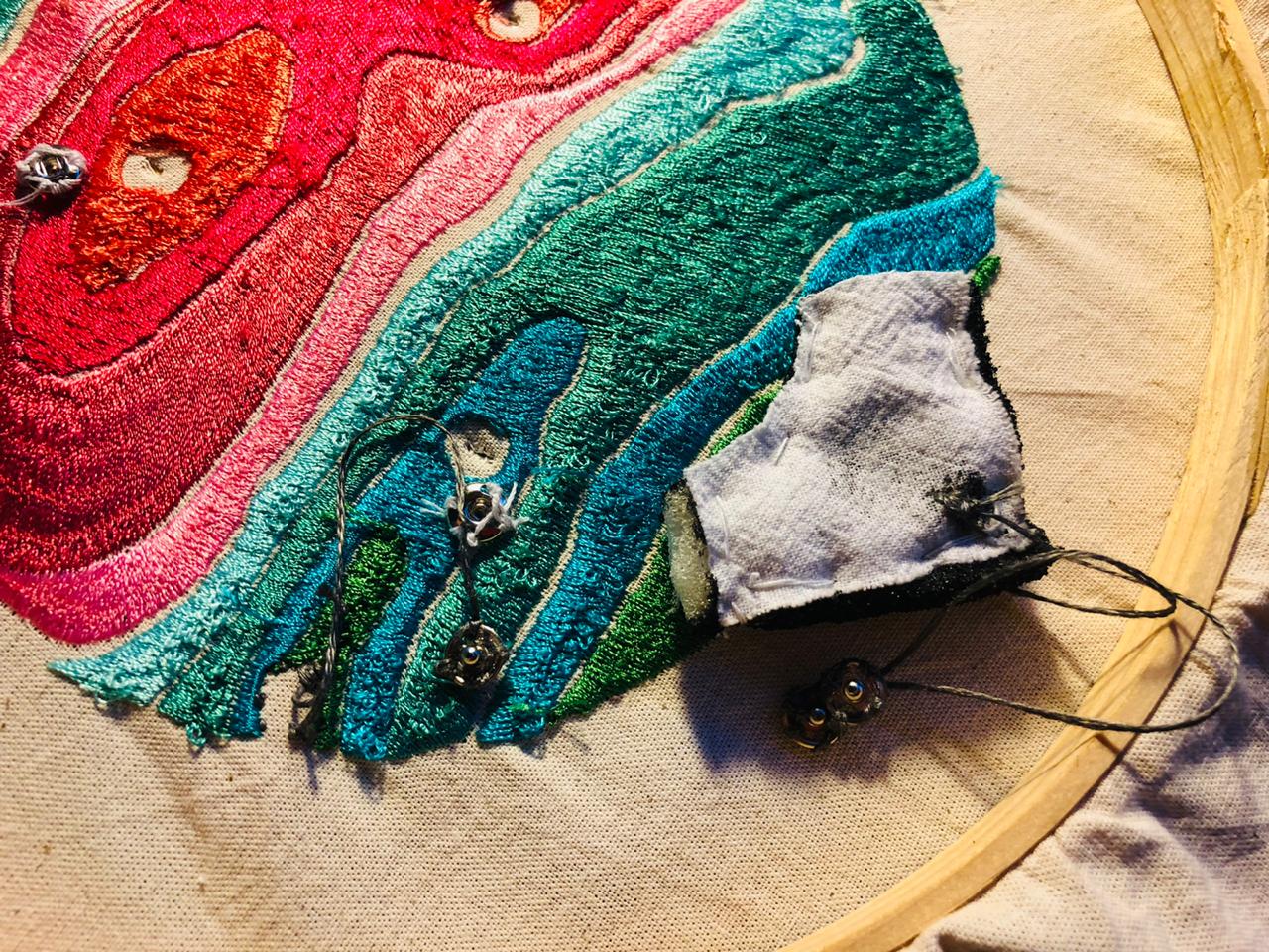
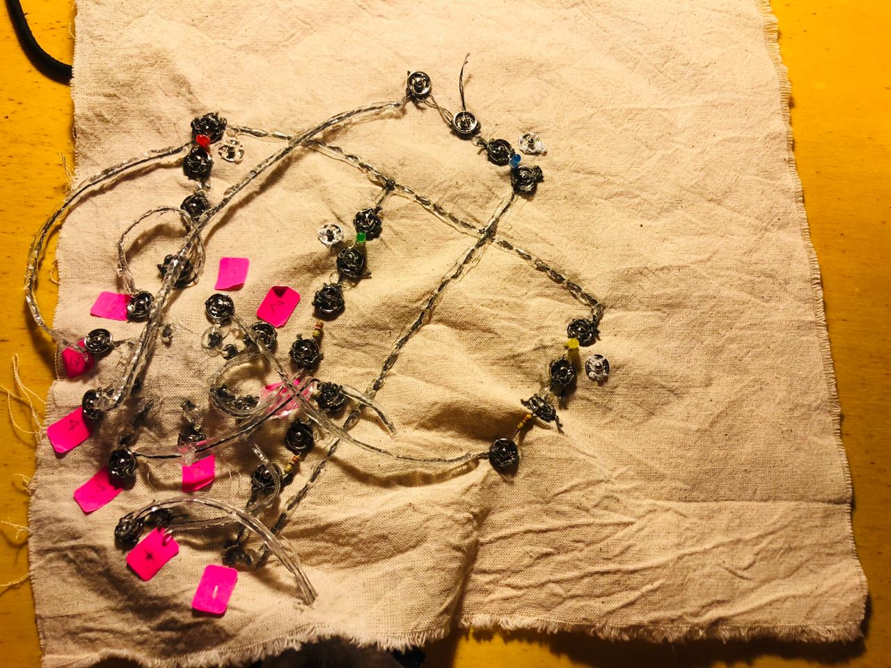
And here is my final circuit, It looks horrible and dirty, I thought it will be look good but with the silicone is not, and also, I really had to work very hard to insulated all the components very perfectly because if they touch each other it wont work. I did it like this way because, once I did a exercise with the lily pad where if you change the pins, you will activate a different component. Even it looks horrible, it works very well hahahahaha
This was my idea, but mine looks horrible hahahaha :(
And finally I sew this pins with normal thread to hold the circuit with the embroidery fabric.
This is the final soft circuit, I know that it looks horrible and dirty but it is working, honestly I though it was not going to work hahahaha. I sew the attiny and the battery in the other way, so, in case i want to re program or change the battery, i don't need to take everything.
circuito horrible from Trinidad Machuca on Vimeo.
Try number one, i pushed my soft button and it turn on two LEDS, its working!
Try number one! from Trinidad Machuca on Vimeo.
Try number two, I pressed the button and all the four LEDs turn on. I feel so happy and grateful with Pablo, He helped me to fixed all, the problem was some resistors that wasn't touching each other.
video todos los leds from Trinidad Machuca on Vimeo.
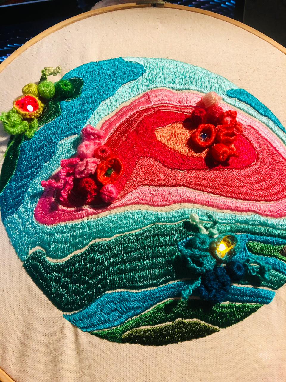
Here you can see how all they look at night. I love it! The circuit is working.
LEDS AT NIGHT from Trinidad Machuca on Vimeo.
FINAL RESULT
IMPORTANT INFORMATION ABOUT THE ASSIGNMENT
LINKS
Download files
Tutors
- Adriana Cabrera General Tutor
- Adriana Cabrera Electronics Tutor
PERSONAL NOTES
- Need to improve my circuit knowles I got too excited in this assignment, I know since more than five years how to make soft circuit but without attiny85, so, at the end I was traying to do something cool but the result was ugly and dirty circuit, I learnt a lot from the mistakes hahaha. Next time I will try to keep it simple.
NECESSARY MATERIALS FOR THIS ASSIGNMENT
| Qty | Description | Price | Link | Notes |
|---|---|---|---|---|
| 0 | Conductive tread | 00.00 $ | ----------- | USD |
| 0 | LED | 00.00 $ | ----------- | USD |
| 0 | RESISTANCE | 00.00 $ | ----------- | USD |
| 0 | FRAME | 00.00 $ | ----------- | USD |
| 0 | NEADLE | 00.00 $ | ----------- | USD |
| 0 | COLOR YARNS | 00.00 $ | ----------- | USD |
CLASS
LEARNING OUTCOMES
- Understand how we can produce soft circuits, sensors and actuators
- Learn how to embed them in garments, soft objects or wearables
- Study and learn soft-hard connections
- Discover necessary materials, components, tools
- Explore and replicate existing projects
STUDENT CHECKLIST
- [x] Build at least one digital and one analogue soft sensors, using different materials and techniques.
- [x] Document the sensor project as well as the readings got using the AnalogRead of Arduino
- [x] Integrate the two soft sensors into one or two textile swatches using hard soft connections
- [x] Document the circuit and it’s schematic
- [x] Document your swatches
- [x] Upload a small video of the swatches functioning
- [x] Integrate the swatch into a project (extra credit)