5. E-textiles
ASSIGNMENT WEEK5
- Build at least one digital and one analogue soft sensors, using different materials and techniques.
- Document the sensor project as well as the readings got using the AnalogRead of Arduino
- Integrate the two soft sensors into one or two textile swatches using hard soft connections
- Document your swatches
- Upload a small video of the swatches functioning
- EXTRA POINT Integrate the swatch into a project
Inspiration

Hello World in Arduino
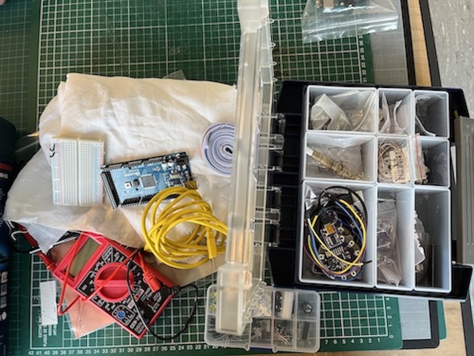
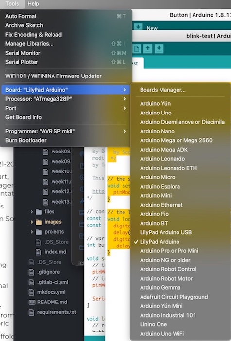
Preparing the needed material. I then set up the arduino with a lily pad board and the USB port.
| The material | Set up the arduino |
|---|---|
 |
 |
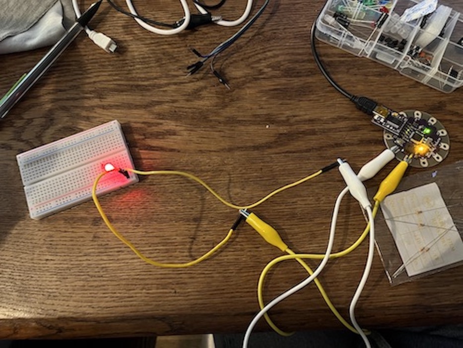
I run the blinking code that turns on the led, then that turns on the LED on for one second, then off for one second, repeatedly. I then added a conductive material into the circuit
/*

// the setup function runs once when you press reset or power the board
void setup() {
  pinMode(5, OUTPUT);
}

// the loop function runs over and over again forever
void loop() {
  digitalWrite(5, HIGH); // turn the LED on (HIGH is the voltage level)
  delay(1000);
  digitalWrite(5, LOW); // turn the LED off (HIGH is the voltage level)
   delay(1000);
}
| Blinking code on breadboard | blinking code with conductive textile |
|---|---|
 |
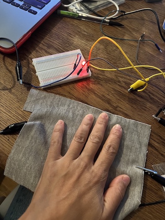 |
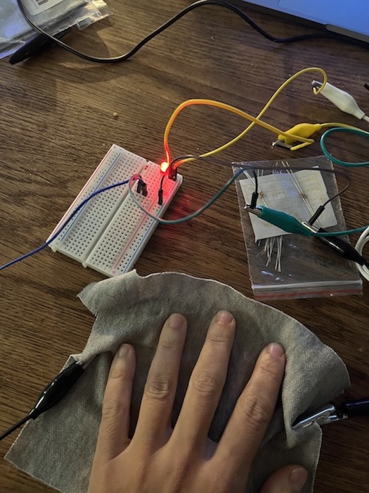
I tested this with the fabric, with copper and with conductive thread. I then tested how manipulating the material would change the power of the led, but it didnt affect it. So I decided to use the fabric as a controler and test the range of it's resistance depending on how to fold it
| Conductive Material | Test with conductive textile |
|---|---|
 |
 |
Analogue input
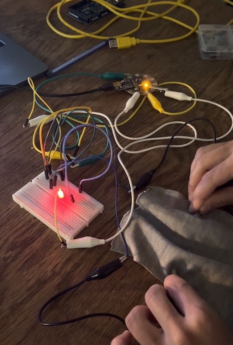
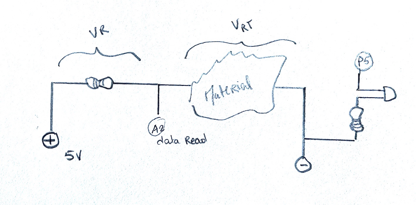
I designed the following circuit, that would read the value of the resistance that comes from the material and calibrate it so that it can map to a frequency that would control the blinking of a LED.
| Circuit | Test on breadboard with conductive material |
|---|---|
 |
 |
The code in arduino is :
/*
  Analog Input
*/

int sensorPin = A2;    // select the input pin for the potentiometer
int ledPin = 5;      // select the pin for the LED
int sensorValue = 0;  // variable to store the value coming from the sensor
float sensorValueCalib = 0;
void setup() {
  // declare the ledPin as an OUTPUT:
  pinMode(ledPin, OUTPUT);
    // initialize serial communication at 9600 bits per second:
  Serial.begin(9600);
}


// H_out = Highest possible output
// L_out = Lowest possible output
// H_in = Highest possible input
// L_in = Lowest possible input
// calib = final calibration
// input = the scaling start-off (probably te analog input)
float mapCalibrate(float H_out, float L_out, float H_in, float L_in, float Calib, float Input){

  return  L_out +  ((Input - L_in) /(H_in - L_in)) * (H_out - L_out) + Calib;
}

void loop() {
  // read the value from the sensor:
  sensorValue = analogRead(sensorPin);
  sensorValueCalib = mapCalibrate(1, 0, 13, 9, 0, sensorValue) * 1000;


  Serial.println(sensorValue);
 Serial.println(sensorValueCalib);
   // turn the ledPin on
  digitalWrite(ledPin, HIGH);
  // stop the program for <sensorValue> milliseconds:
  delay(sensorValueCalib);
  // turn the ledPin off:
  digitalWrite(ledPin, LOW);
  // stop the program for for <sensorValue> milliseconds:
  delay(sensorValueCalib);
// print out the value you read:

}
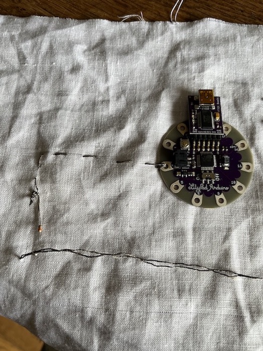
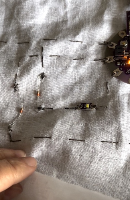
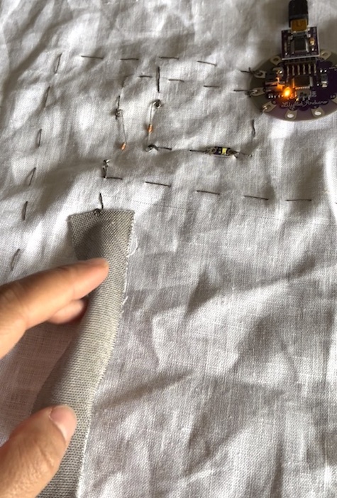
I tested it on the Breadboard.Then integrated it into fabric with the lilypad using conductive thread. I curled and connected the resitors and the LED. I tested it, and it works !!! It blinks with the frequency that depends on how I manipulate the fabric
| test with conductive textile on lilypad | integrating the resistors |
|---|---|
 |
 |
 |
Digital input
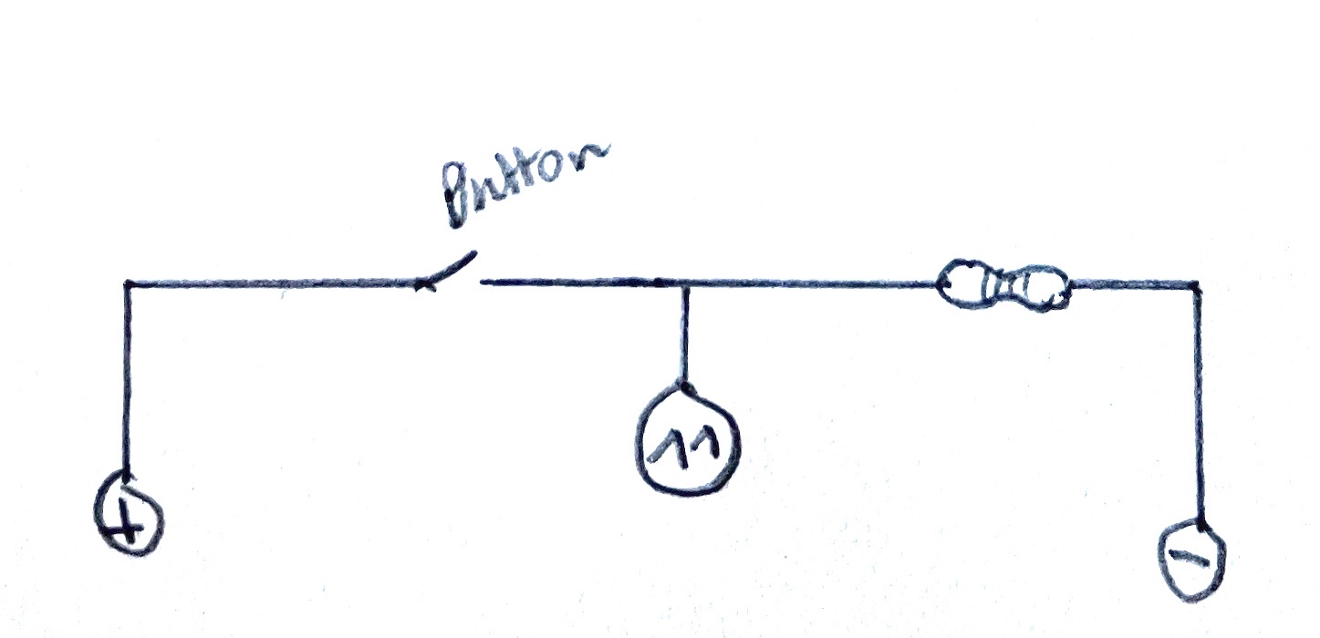
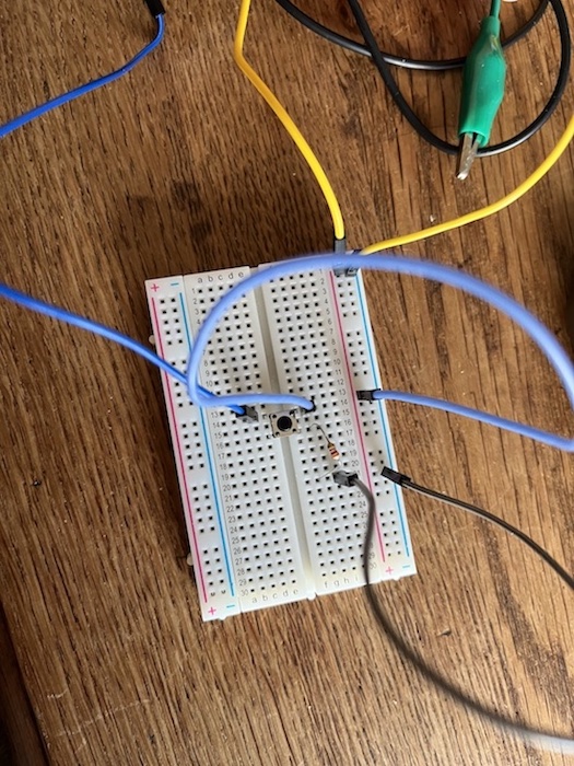
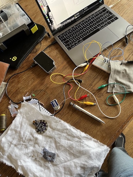
In order to design a button, first I tried the following code with an actual button on the Breadboard.
The circuit is very simple. I tested the circuit on the Breadboard using an industrial button :
| Circuit | Test on breadboard |
|---|---|
 |
 |
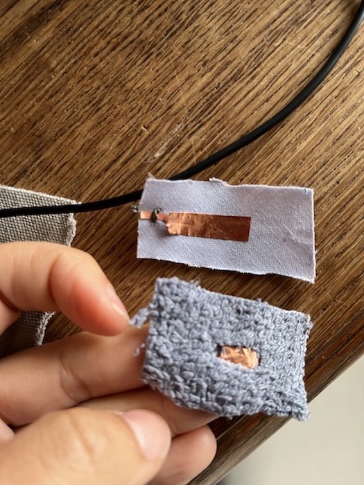
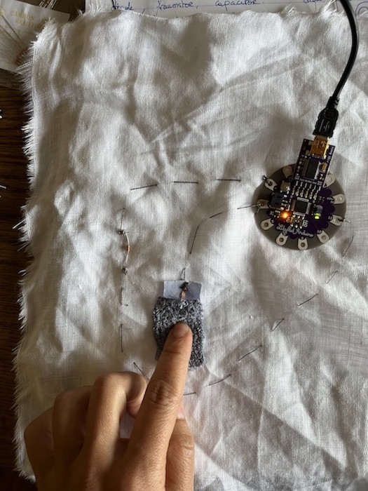
I then designed a fabric based button - so a digital sensor- that when pressed would close the circuit:
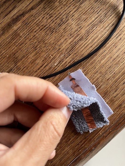
| Inside the sensor: | When you push the two sides one against the other: |
|---|---|
 |
 |
I run the following code on both, it worked, it made the LED go on when both buttons are pressed.
/*
  Button

// constants won't change. They're used here to set pin numbers:
const int buttonPin = 11;     // the number of the pushbutton pin
const int ledPin =  13;      // the number of the LED pin

// variables will change:
int buttonState = 0;         // variable for reading the pushbutton status

void setup() {
  // initialize the LED pin as an output:
  pinMode(ledPin, OUTPUT);
  // initialize the pushbutton pin as an input:
  pinMode(buttonPin, INPUT);

  Serial.begin(9600);
}

void loop() {
  // read the state of the pushbutton value:
  buttonState = digitalRead(buttonPin);

  // check if the pushbutton is pressed. If it is, the buttonState is HIGH:
  if (buttonState == HIGH) {
    // turn LED on:
    digitalWrite(ledPin, HIGH);
  } else {
    // turn LED off:
    digitalWrite(ledPin, LOW);
  }

  Serial.println(buttonPin);
  delay(1000);
}
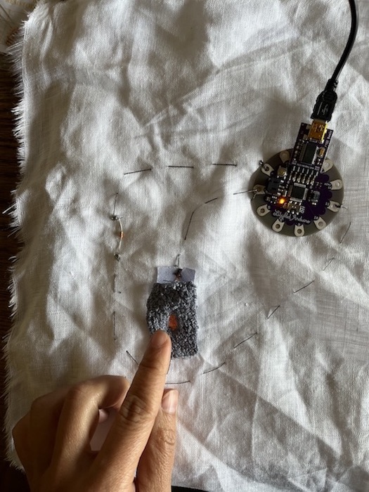
I integrated that into fabric with a circuit with conductive thread
| The sensor in the fabric | The circuit in the fabric |
|---|---|
 |
 |
The result works, when I press the LED goes on:
| Controling the LED with the sensor | More images |
|---|---|
 |
 |