8. Wearables
ASSIGNMENT WEEK8
- Document the concept, sketches, references also to artistic and scientific publications
- Create a swatch using an ATtiny with one input and one output, using hard-soft connection solutions and battery
- Create 2 actuator swatches. Test them with the Arduino or ATtiny.
- Learn how to program and ATTiny , add the libraries and links used for the code
- Document the schematic and the programming code, the libraries added and the power requirements
- Upload a small video of your object working
- EXTRA POINT Integrate it to a project
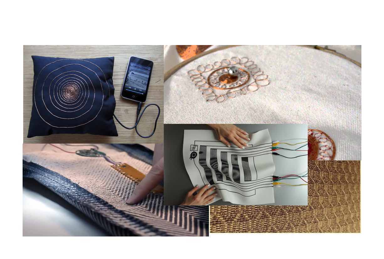
Inspirations :
Swatch using ATiny with input and output:
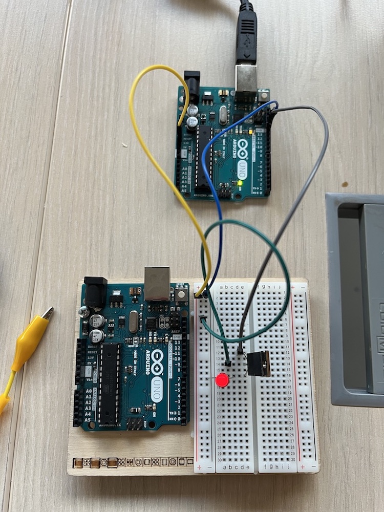
In order to program the ATiny, I followed the following tutorial
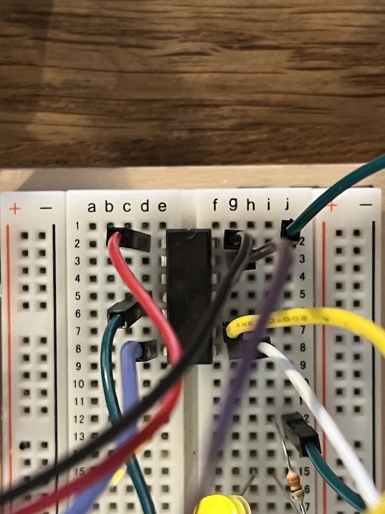
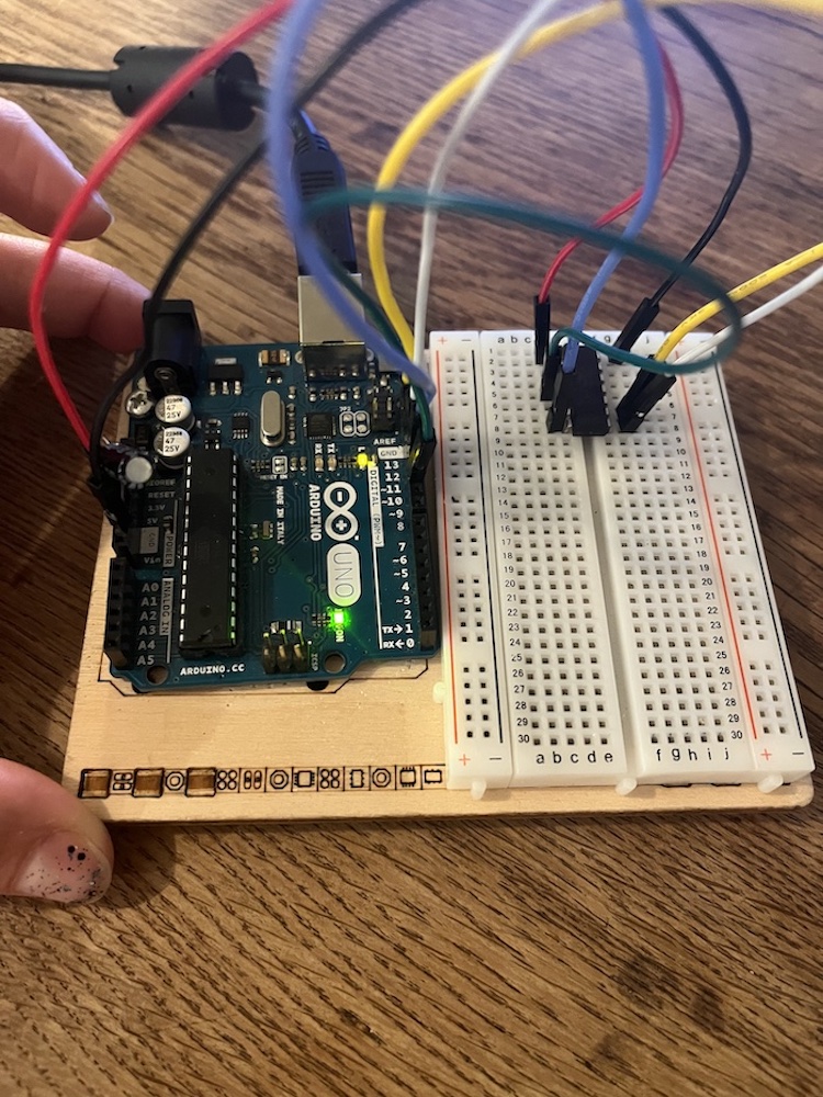
I used the Arduino Uno as an In-System Programmer or ISP. An ISP allows AVR microcontrollers to be programmed and reprogrammed without having to remove them from the circuit. To program any AVR microcontroller six wires are needed. Three of these wires are referred to as the Serial Peripheral Interface (SPI) and are the Master In - Slave Out (MISO), Master Out - Slave In (MOSI), and Serial ClocK (SCK). The "Master" is the ISP or the device you are using to program the AVR chip. The "Slave" is the AVR chip being programmed. The other three wires are for the 5V power supply (VCC), Ground (GND), and Reset (RESET).
Here is the wiring schematic for the ATiny84 (which is what I used)
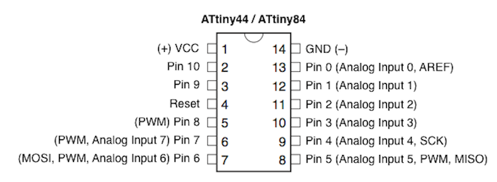
-
step 1 : Add Support for ATtiny - adding the following link into Additional Boards Manager URLs in the preferences : https://raw.githubusercontent.com/damellis/attiny/ide-1.6.x-boards-manager/package_damellis_attiny_index.json
-
step 2 : Setup Arduino As ISP - open the example ArduinoISP upload it to the Arduino
-
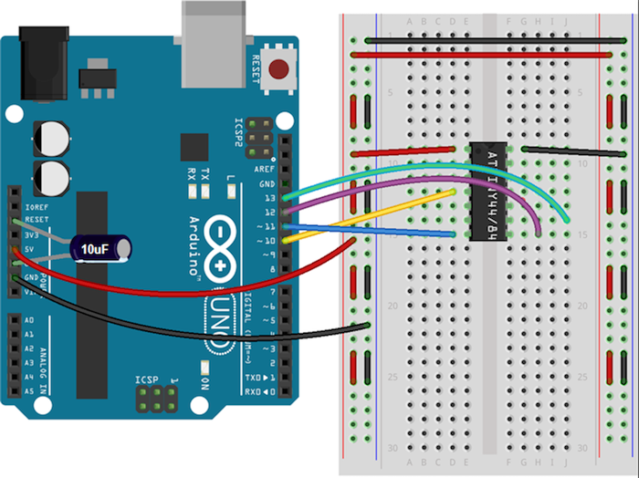
step 3: Connect Components -
- 10 μF Capacitor to the Ground and Reset Pins
- Arduino Pin 13 ---> SCK
- Arduino Pin 12 ---> MISO
- Arduino Pin 11 ---> MOSI
- Arduino Pin 10 ---> RESET
- Arduino 5V ---> VCC
-
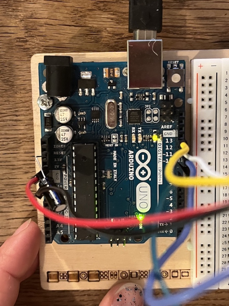
Arduino Ground ---> GND Here is how I linked the Atiny84 to Arduino
-
change the frequency of the communication with arduino - The ATtiny runs at 1 MHz by default. You will need to change this to be 8 MHz so that it can communicate with the Arduino at the same frequency.
- Select ATtiny from Tools > Board.
- Select the specific ATtiny you are using (44/45/84/85) from Tools > Processor.
- Select "8 MHz (Internal)" from Tools > Clock
- Select "Burn Bootloader" under tools and wait for it to complete.
| The wiring of the ATiny84 | More images |
|---|---|
 |
 |
 |
- Make a Led Blink on the Atiny Upload the blink basic example on Arduino
/*
  Blink

  Turns an LED on for one second, then off for one second, repeatedly.
  This example code is in the public domain.

  https://www.arduino.cc/en/Tutorial/BuiltInExamples/Blink
*/
int led = 0;

// the setup function runs once when you press reset or power the board
void setup() {
  // initialize digital pin LED_BUILTIN as an output.
  pinMode(led, OUTPUT);
}

// the loop function runs over and over again forever
void loop() {
  digitalWrite(led, HIGH);   // turn the LED on (HIGH is the voltage level)
  delay(1000);                       // wait for a second
  digitalWrite(led, LOW);    // turn the LED off by making the voltage LOW
  delay(1000);                       // wait for a second
}
-- See video downwards for a demo of the blinking led.
Actuator swatche : speakers
We made a circuit that amplifies sound.
The circuit is as such :
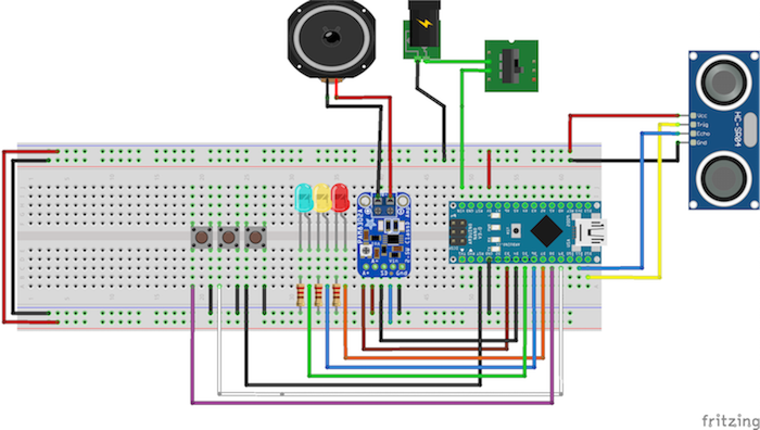
The instructions to make it work are to be found in the following link.
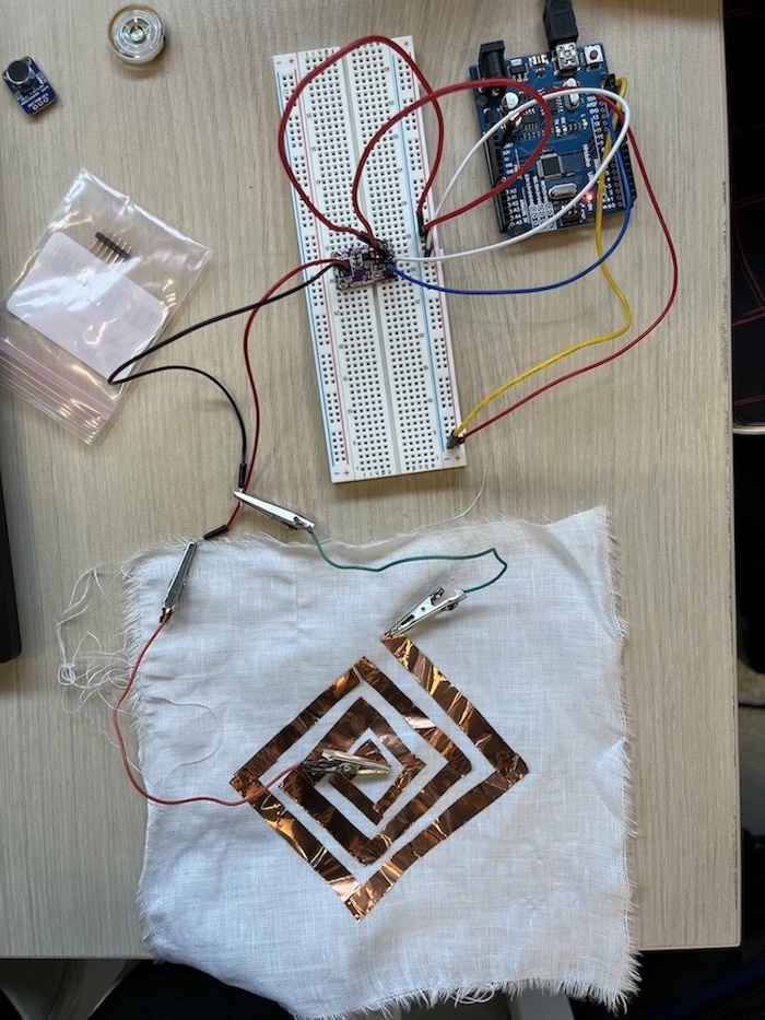
- We simplified the circuit using the amplifier and with an actual speaker to test that it works.
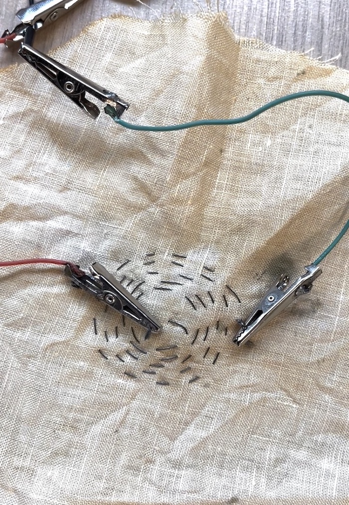
- We then used a fabric with a spiral of conductive thread and a magnet underneath the fabric. We could hear a very low sound, which was not well captured by video. But still the textile and magnet worked as a speaker.
- We tried to replicate another spiral with coper on fabric and a magnet underneath but it seem to be more difficult to hear it, perhaps the spiral was not tight enough...
| Testing with amplifier | Speaker on fabric |
|---|---|
 |
|
 |
 |
-- See video downwards for a demo of the speakers.
Actuator swatche : colour
-
In order to change the color of a fabric we applied a thermochromic paint onto coton textile.
-
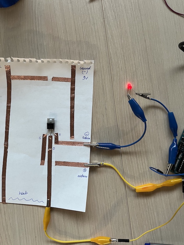
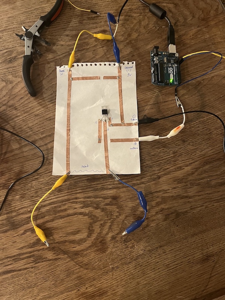
We then designed a circuit that uses coper paper and a mosfet in order to pass 9V voltage into a conductive thread that would heat the textile and thus change its color.
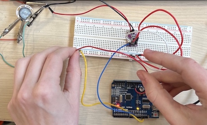
In order to understand how the mosfet fonctions, I used it on the breadboard with a LED. I then used the arduino to pass electricity and the close the gate of the mosfet with a LED :
| Testing the mosfet with a led | testing the coper circuit |
|---|---|
 |
 |
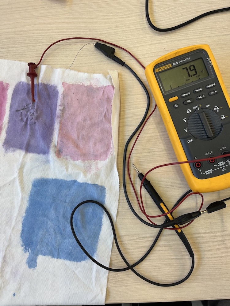
I then tried to use the circuit with a conductive wire to be heated. The problem with the conductive wire was that it did not have much resistance and therefore could not transform electricity into heat and change the color of the textile.
I decided to use a conductive wire Nitinol, that has a high resistance and can get very hot with 9V electric voltage passed by it:
| Testing the resistance of conductive wire | testing with the nitinol wire |
|---|---|
 |
 |
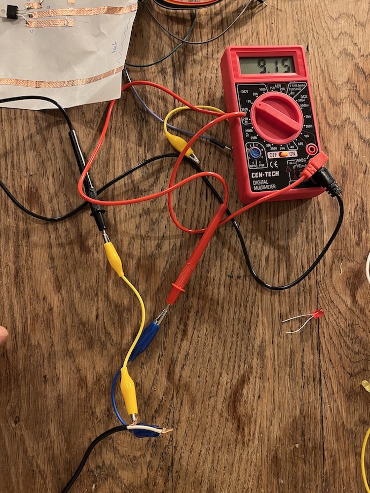
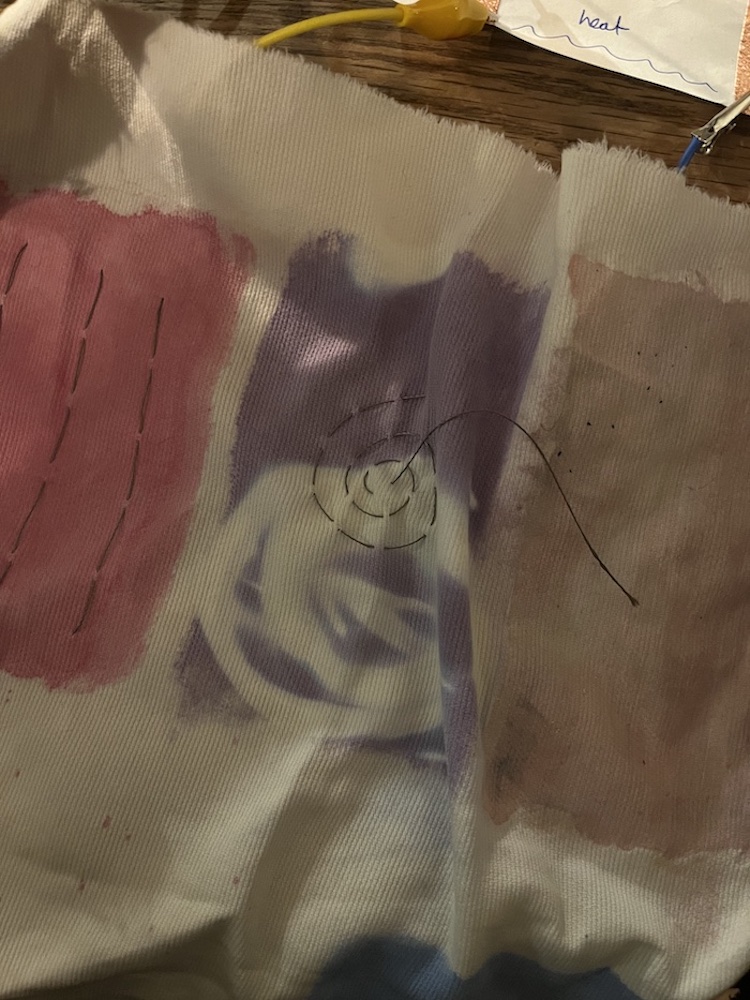
I hacked an electric power supply and tested that it delivered a 9V electric voltage through the paper circuit. It worked pretty well ! The nitinol heated the textile and changed its color as following :
| Hacking the power supply for 9V | using the nitinol wire on thermochromic textile |
|---|---|
 |
 |
-- See video downwards for a demo of the changing color.