13. Skin Electronics
Tuesday's Class
Fabricademy 2022-23 Week 7 - Skin Electronics
I see this week as the continuation of the week 5 E-TEXTILE and the week 8 WEARABLES. However, we crossed the construction of electronic circuits and our body, more precisely our skin and human gestures. My objective of this week is to include an ATtiny in a portable electronic circuit and to understand how a matrix works.
Research
MALOU BEEMER
with the partners: Fraunhofer IZM, Profactor, EMPA and Wear It Berlin.
This projet is an intelligent Textile, crossing electronique with humain. I find this project both very technical and very poetic. It is very sensory, the touch and the sight are very present.
The question initiating the project :
‘How is it possible that we surround ourselves with passive and polluting garments, while we live in a world that is becoming “smarter” every day?’ Malou Beemer
Second Skins
It is hard for me to imagine putting an electronic circuit on my own skin. I don't know if it could cause burns because of the energy lost when the circuit is running. Also, the electrical energy could potentially affect the internal energies of the body. Therefore, this week I did not try to create an electronic system to put on my skin, but rather a suit.
Setting up before starting a project
Preparation to program an ATtiny with an Arduino board
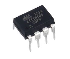
The ATtiny 85 can be seen as a small transportable Arduino with a more limited memory. It is a microcontroller that can only be programmed with an Arduino (relay).
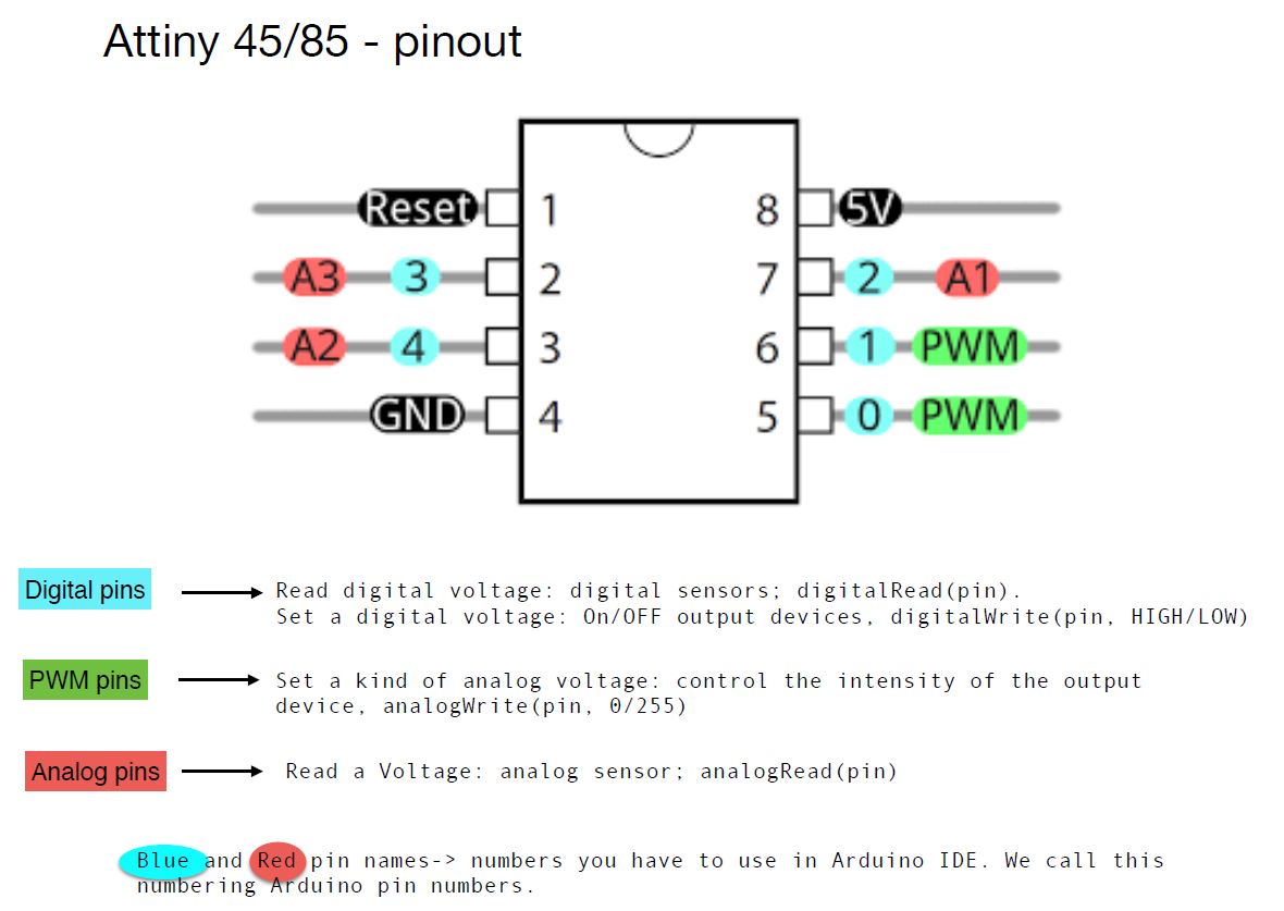
Attiny has its own way of working that is important to understand for writing code and also for the realization of future wearable electronic circuits.
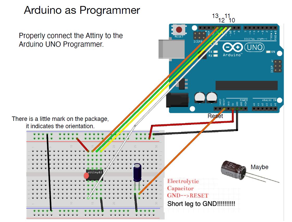
Arduino must become a relay
Before you can really use this object, you must configure the arduino and the arduino IDE to include a code in the Attiny.
- Connecting the arduino board to the computer
- Connect to IDE Arduino
- The port of the Arduino must be recognized by the computer
- Go in File -> Examples -> Arduino ISP -> Arduino ISP
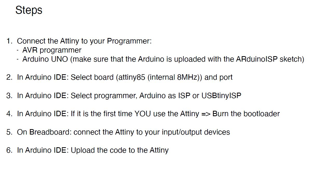
Make the connection to code the ATtiny with Arduino
After connecting, you must check that the computer recognizes the ATtiny and if necessary download the attiny library. If not, here is the link to upload in Board Manager : https://raw.githubusercontent.com/damellis/attiny/ide-1.6.x-boards-manager/package_damellis_attiny_index.json.
It is important to check if the Arduino IDE recognizes the attiny 85 with the port. Follow the steps that Emma gives in her class :
When the connection is made, the ATiny is well recognized, the library is present in the Arduino IDE, you just have to write the code script with the right pins (according to the ATtiny and not the Arduino) and go to SKETCH -> UPLOAD USING PROGRAMMER.
If no error message is displayed, the ATtiny is ready to be included in an electronic circuit.
Projet : Illuminated glove
Goal: Code an attiny and create a portable circuit near the skin.
The next project is directly inspired by Thanos' glove. For this week, it was difficult for me to think of an object with wearable electronics that would have a function other than aesthetic. Therefore, and after discussing with Lauriane, I decided to opt for a project where the movement of the handle activates a digital button and thus turns on neo pixels. The anatomical action of the hand closes an electrical circuit with an electronic component.
Inspiration
Thanos' glove in The Avengers

Sketch circuit and glove
The idea to activate the neopixels of the glove is to use the middle finger to press in the palm of the hand and press the digital switch.
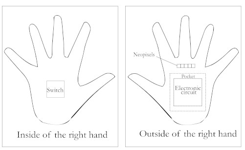
Something like this
At this stage, it was necessary to draw a circuit to understand all the necessary connections to set up.
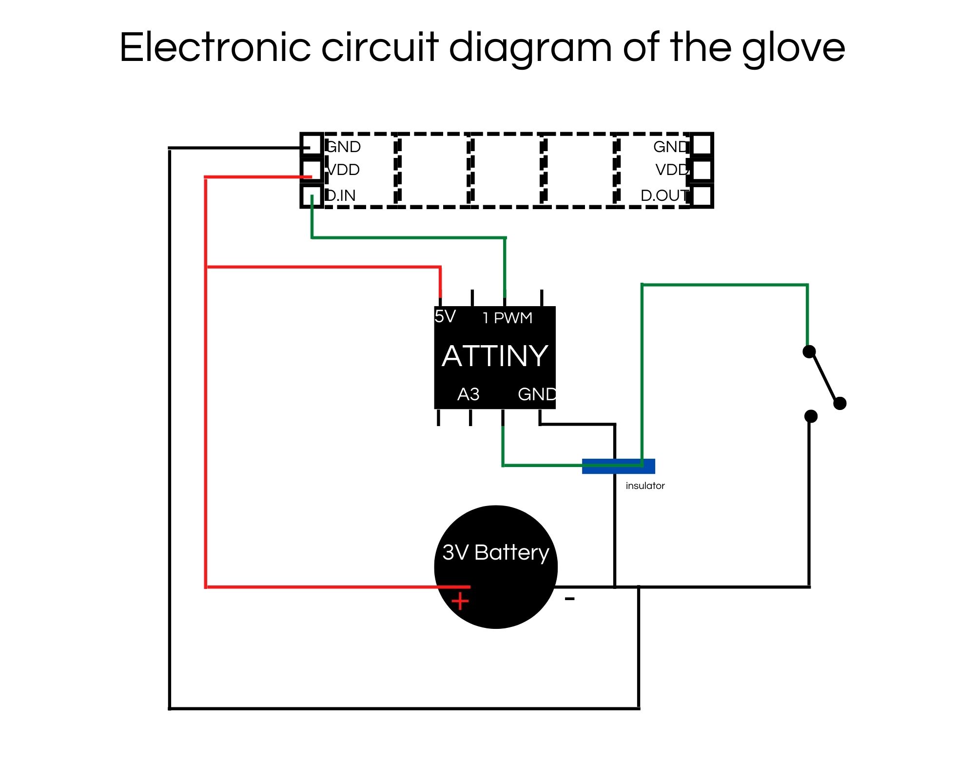
Tools
- ATtiny 85
- 5 Neopixels
- Conductive threads
- Non-conductive threads
- Sewing needle
- 3V Battery
- Digital sensor
Code Arduino
To program the attiny, I used Emma's class which you can find here. I used Emma's wipe code, changing the delay and adding a color.
#include <Adafruit_NeoPixel.h>
#define LED_PIN    1
#define LED_COUNT 5
Adafruit_NeoPixel strip(LED_COUNT, LED_PIN, NEO_GRB + NEO_KHZ800);
uint32_t off = strip.Color(0, 0, 0);
int sw_pin = 3;
int sw_status = 0;

void setup() {
  strip.begin();
  strip.show();
  strip.setBrightness(50);
  pinMode(sw_pin, INPUT_PULLUP);

}
void loop() {
   sw_status = digitalRead(sw_pin);
   if (sw_status == 0){
      colorWipe(strip.Color(255,   0,   0), 50);
      strip.fill(off, 0, 10);
      strip.show();
      colorWipe(strip.Color(0,   0,   255), 50);
      strip.fill(off, 0, 10);
      strip.show();
      delay(500);
    }
}
void colorWipe(uint32_t color, int wait) {
  for(int i=0; i<strip.numPixels(); i++) {
    strip.setPixelColor(i, color);
    strip.show();
    delay(wait);
  }
}
Testing electronic circuit
Before we started sewing on a textile backing, Diane strongly recommended that we test the circuit. So I used a sheet of paper, pieces of tape and conductive thread to test it. This step took longer than expected, because the smaller the circuit, the more meticulous you have to be.
After this circuit validation, it was time to move on to sewing to include my circuit on a textile.
... 6 HOURS LATER...
Wearable circuit
Creation of the glove to include the circuit.
For this part, I used Lauriane's modules that she created in week 3. The link to her page is here. At this point, I had to build a glove with the modules and also design the pocket to hide my electronic circuit.
This part was a bit chaotic for me. I needed patience and I was out of patience. It was the end of the week, my energy gauge was empty. So I tried to make a glove, I promise you this thing is a glove or rather the beginning of a glove.
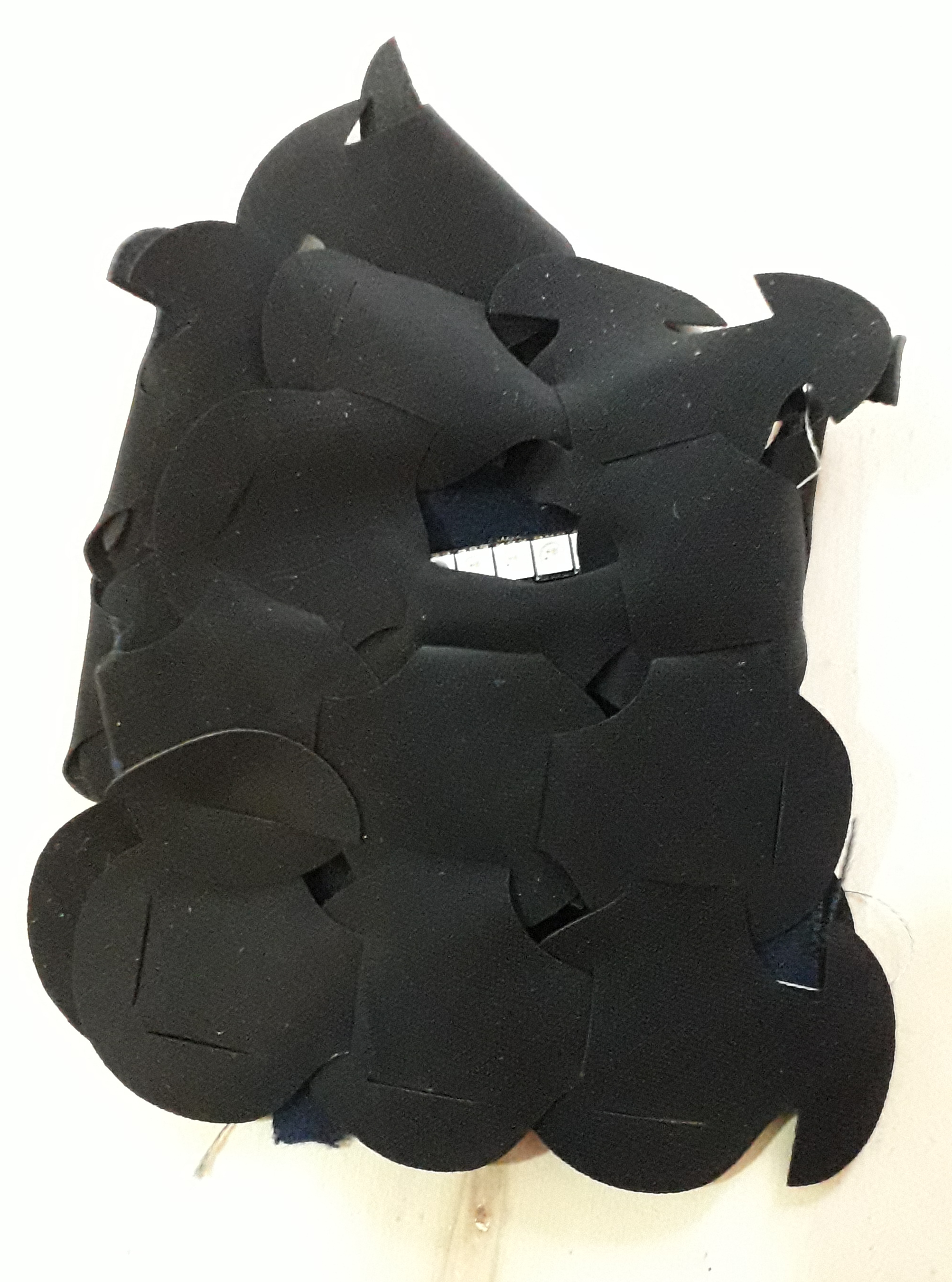
The result after one week :
I ran threads around the sides of the hand to put the digital button in the palm of the hand. The circuit is so sensitive that the neopixels didn't always work. Sometimes only four would light up and the blue would disappear. The wires would wear out and the battery would run down...
Experience Feedback : We should think about a more rigid electrical circuit with sheathed conductor lines to avoid wear and tear of the wires by friction. The second important element that I did not realize in this project is to size the current (A), voltage (V) and resistance (Ohms) to match the power source to the power needed for the neopixels. I strongly believe that the blue wipe is no longer displaying due to lack of power.
Approach a new abstract logic : Matrix
What is a matrix ?
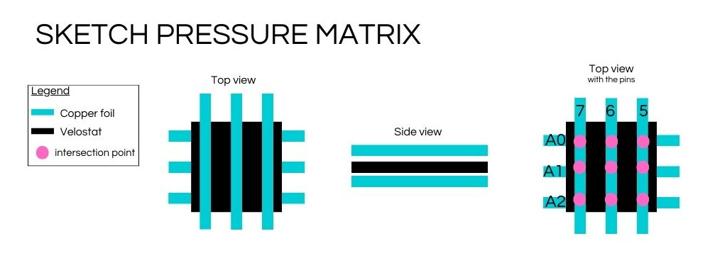
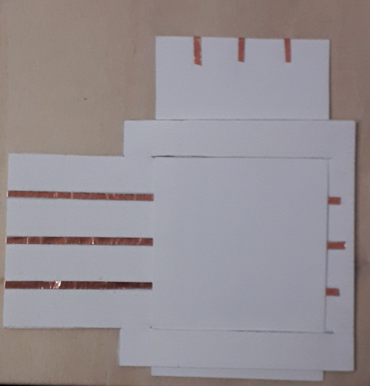
A matrix is an array of values containing a number of elements, organized in columns and rows. The number of elements is variable, as are the number of columns and rows. Each element of the matrix is a given piece of information (a color, a sound, etc.). . In this week's lesson, we created a matrix system to set up a multi-value touch pad.
Creating a matrix
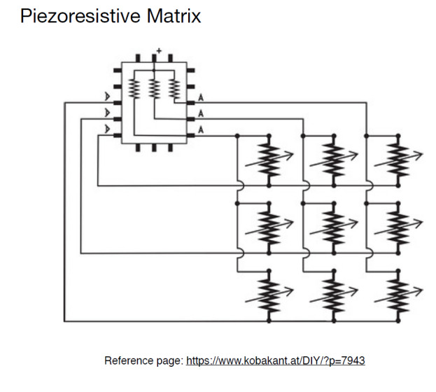
To make a matrix, we used the Kobakant’s tutorial, we can find here.
This matrix made by Audrey :
Code matrix :
The code used comes from Emma's tutorial.
#define numRows 3
#define numCols 3
#define sensorPoints numRows*numCols

int rows[] = {A0, A1, A2};
int cols[] = {5,6,7};
int incomingValues[sensorPoints] = {};

void setup() {
for (int i = 0; i < numRows; i++) {
pinMode(rows[i], INPUT_PULLUP);
}
for (int i = 0; i < numCols; i++) {
pinMode(cols[i], INPUT);
}
Serial.begin(9600);
}

void loop() {
for (int colCount = 0; colCount < numCols; colCount++) {
pinMode(cols[colCount], OUTPUT);
digitalWrite(cols[colCount], LOW);

for (int rowCount = 0; rowCount < numRows; rowCount++) {
incomingValues[colCount * numRows + rowCount] = analogRead(rows[rowCount]);
}

pinMode(cols[colCount], INPUT);
}

for (int i = 0; i < sensorPoints; i++) {

  Serial.print(incomingValues[i]);
  if (i<(sensorPoints-1)){
  Serial.print("\t");}
}
Serial.println();
delay(10);
}
Electrical connection for the matrix
Testing
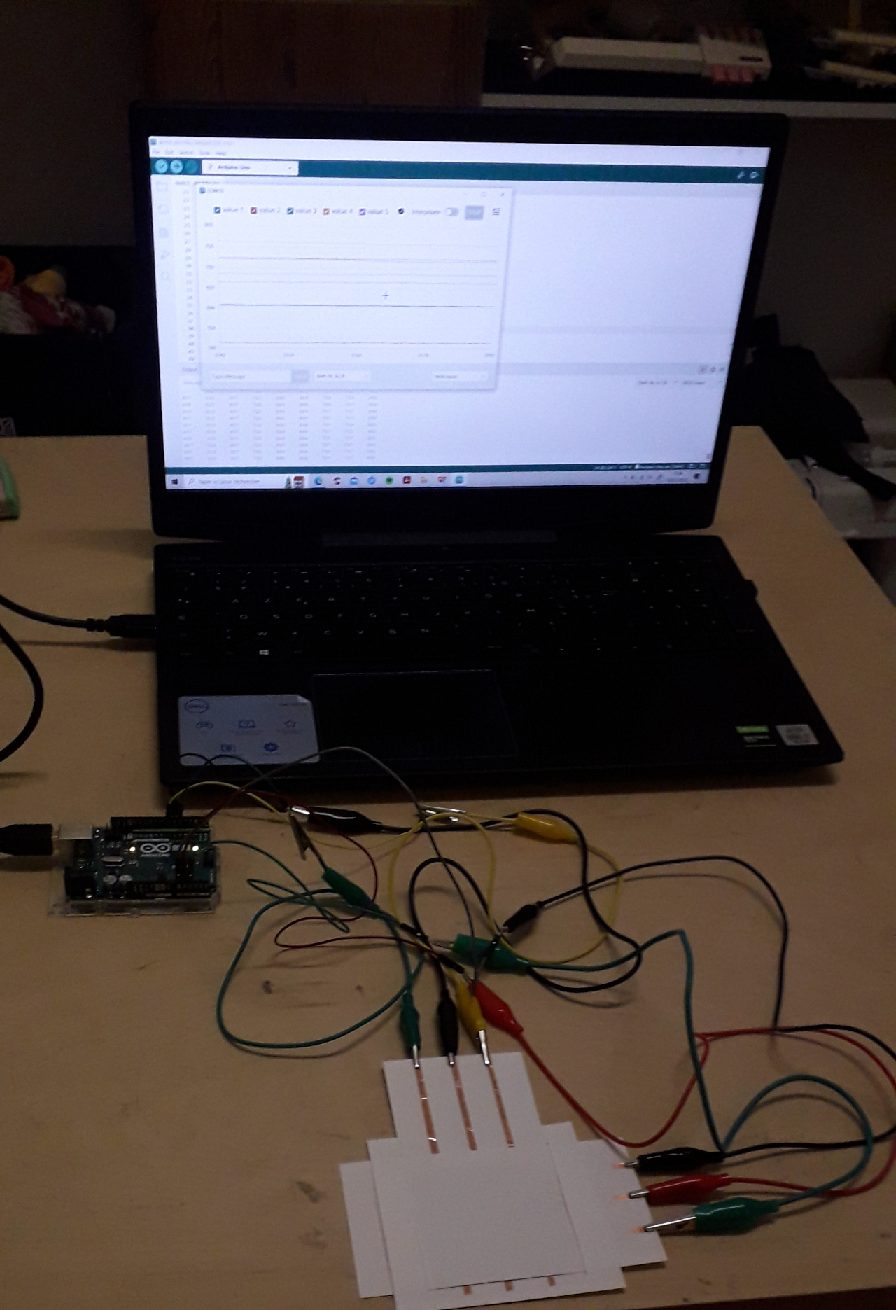
The following videos were made by Lauriane. I had not succeeded in making Processing 3D work with last year's codes. So I accompanied Lauriane when she made this connection with this year's Arduino codes.