08 WEARABLES
RESEARCH
I'm interested in making my own fabric speakers for this week so I looked into how speakers work.
And whether or not speaker polarity impacts sound quality. ( the answer is no!)
I still have some things left unclear from the e-textiles week so some videos for myself to understand better the function of different components in electronics.
A transistor is a miniature semiconductor that regulates or controls current or voltage flow in addition amplifying and generating these electrical signals and acting as a switch/gate for them.
When working as an amplifier, a transistor transforms a small input current into a bigger output current. As a switch, it can be in one of two distinct states -- on or off -- to control the flow of electronic signals through an electrical circuit or electronic device.
How do you know which resistor to use:Types of Resistors and How To Choose One
ARDUINO
Arduino Language for coding.
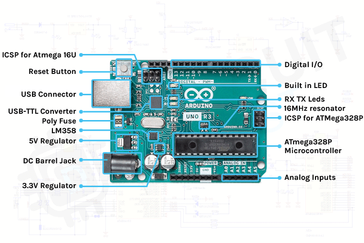
ARDUINO BOARD
Arduino UNO is a low-cost, flexible, and easy-to-use programmable open-source microcontroller board that can be integrated into a variety of electronic projects. This board can be interfaced with other Arduino boards, Arduino shields, Raspberry Pi boards and can control relays, LEDs, servos, and motors as an output.
BREADBOARD
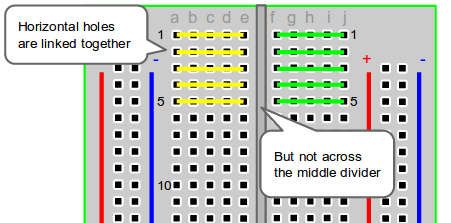
A breadboard is a plastic piece with conductive channels. It’s a solder-less way to connect wires, sensors, and devices to these ports to create prototypes, devices, and electronic circuits.
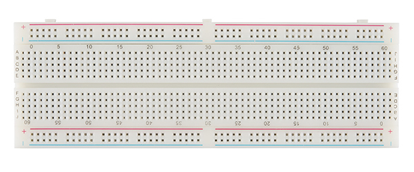
Breadboards are composed of 3 parts:
-
Horizontal Rows (yellow and green lines)
-
Vertical Columns
-
Power (red) /Ground (blue) Rails
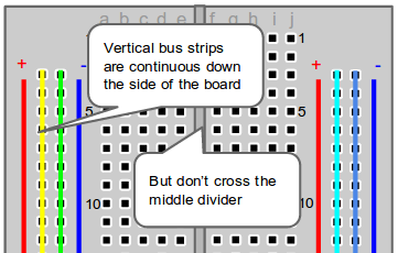
The middle divider separates both sides. So if wire power and ground to one side of the breadboard, you will also need to power/ground the other side.
When wiring a breadboard, be sure that the wires lay flat and are attached neatly to the board. It is important to label wires that are attached to important sensors or actuators.
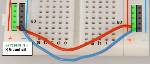
There are two sets of power rails that run along the edges of the breadboard. Rails are marked black/blue for ground (-) and red for power (+).
Each rail is independent of another, so you will have to connect the left positive rail to the right positive rail and the left negative rail to the right negative rail to supply power to both sides of the breadboard.
Once you’ve configured the power rails on the breadboard, you can use it to expand ports on a microcontroller, such as an Arduino by:
-
Connect a red wire from the Arduino Uno 5V to the breadboard + power rail.
-
Connect a black wire from the Arduino GND (ground) to the breadboard – ground rail.
Note: It is common to use red for POWER and black or blue for GROUND, but you don't have to use red and black wires. Whichever colors you use, be consistent so that you don’t mix the POWER and GROUND channels.
NOTES FROM EMMA'S TUTORIAL
If you connect an input you have to select the right pin depending on the sensor
Digital sensors:all the 10 pins are good
Analog sensors: can be connected only the A0/A5 pins
If you connect an output you have to select the right pin depending on how you want to control the device
Digital way: all the IO pins are good
Analog way: you can use only the PWM pins (~)
PROGRAMMING WITH ARDUINO UNO
CODE
int signal_pin = 3; //define the pin where the Arduino pin (signal) is connected

void setup() {

pinMode(signal_pin, OUTPUT); //define pin of the Led as an output
//pinMode(pin, OUTPUT);

//pinMode(pin, INPUT);
//pinMode(pin, INPUT_PULLUP);
}

void loop() {

digitalWrite(signal_pin, HIGH); //turn the Led on
//digitalWrite(pin, HIGH/LOW);
//HIGH -> 5V
 //LOW -> 0V ground
 delay(1000);                 //wait 1000millisecond
 digitalWrite(led_pin, LOW);  //turn off
 delay(1000);                 //wait 1000millisecond

}
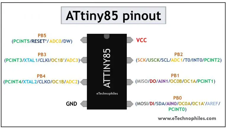
ATTINY 85
ATtiny85 comes with a serial peripheral interface (SPI) that is mainly used for communication between the microcontroller and other peripheral devices such as SD cards, sensors, and shift registers.
I followed this tutorial to program my ATtiny: How to Program an Attiny85 From an Arduino Uno and you can find all the information about the programming process there.
CODE
// the setup function runs once when you press reset or power the board
void setup() {
  // initialize digital pin LED_BUILTIN as an output.
  pinMode(LED_BUILTIN, OUTPUT);
}

// the loop function runs over and over again forever
void loop() {
  digitalWrite(LED_BUILTIN, HIGH);  // turn the LED on (HIGH is the voltage level)
  delay(1000);                      // wait for a second
  digitalWrite(LED_BUILTIN, LOW);   // turn the LED off by making the voltage LOW
  delay(1000);                      // wait for a second
}
TESTING THE CIRCUIT BY CONNECTING IT TO A 3V BATTERY
SPEAKER
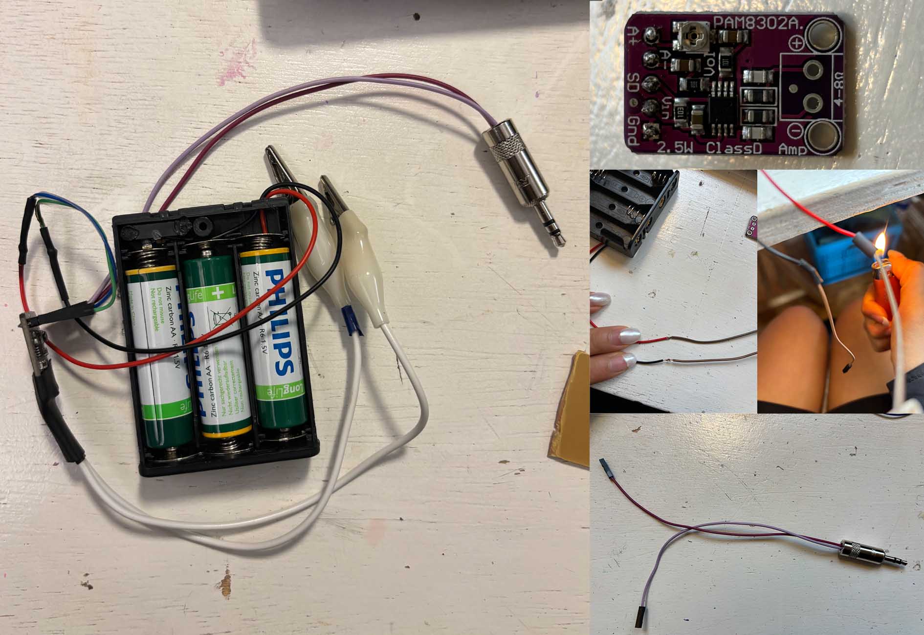
MAKING AN AUDIO AMPLIFER
I followed Liza's tutorial on making a Custom Mono Amp for Textile Speakers.
TOOLS
-
Diagonal snips
-
Wire stripper
-
Soldering iron
-
Lighter
MATERIALS
-
Lipo socket
-
Adafruit PAM8302
-
Audio cable
-
Alligator clip
-
Heat shrink (different sizes)
-
Solder
-
Lipo battery
CONSTRUCTION
- LiPo Battery Holder
TESTING MY AUDIO AMP
I noticed that, in order to get optimal sound quality:
-
your original sound source has to be high quality
-
your volume shouldn't be too high
-
bass creates a lot of buzzing sound
-
classical music normally works really well!
INSPIRATION
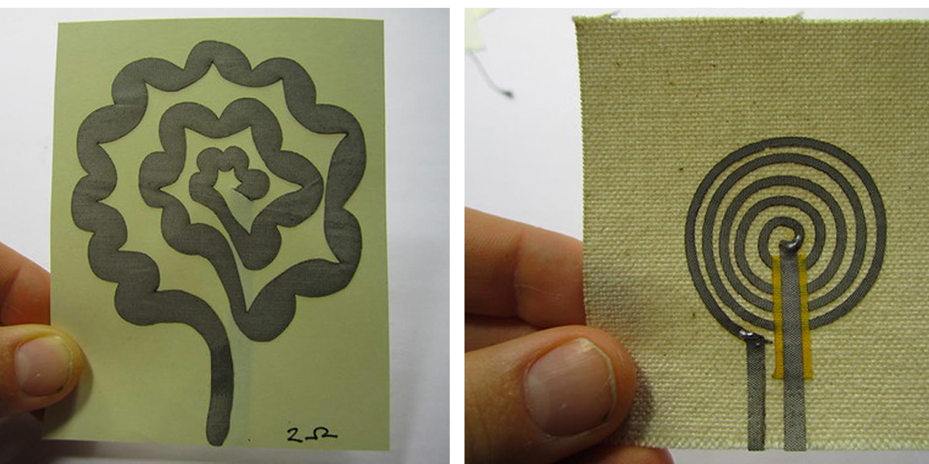
I really like these speakers by Kobakant and would like to make my own fabric speakers.
1ST SPEAKER
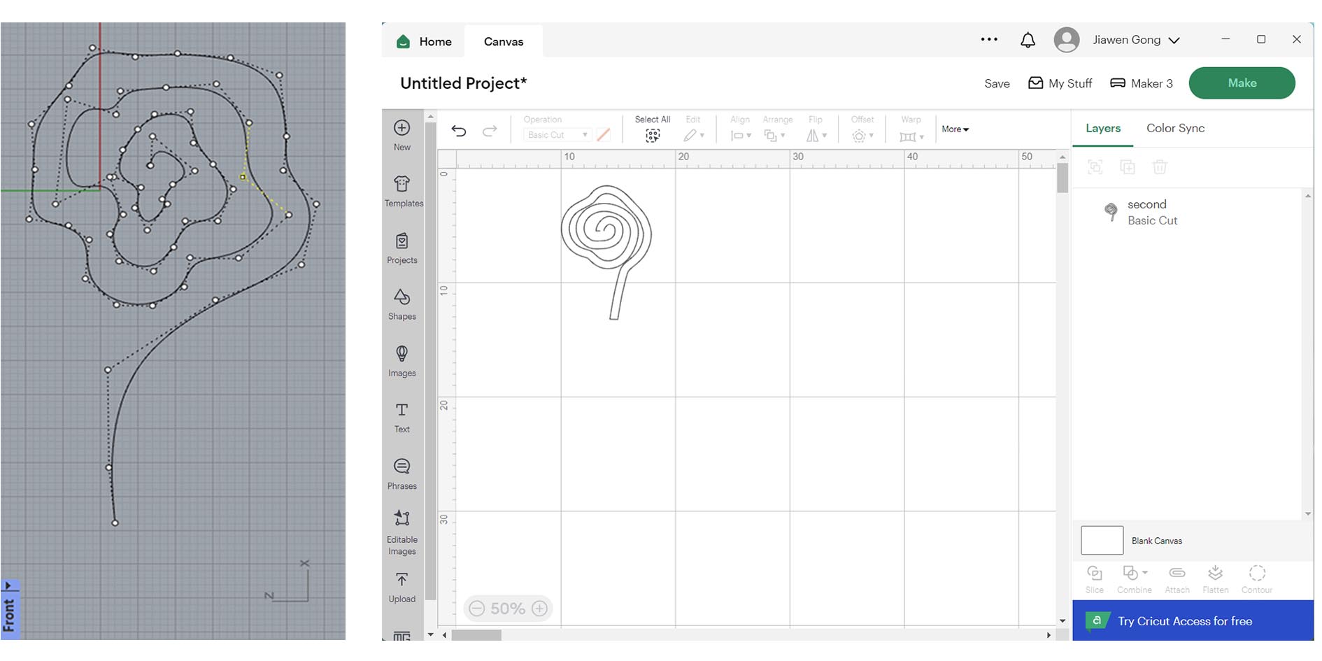
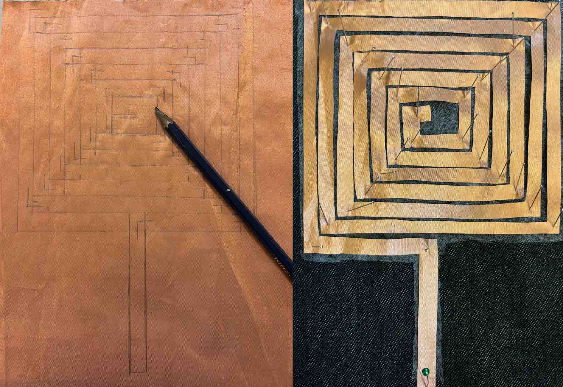
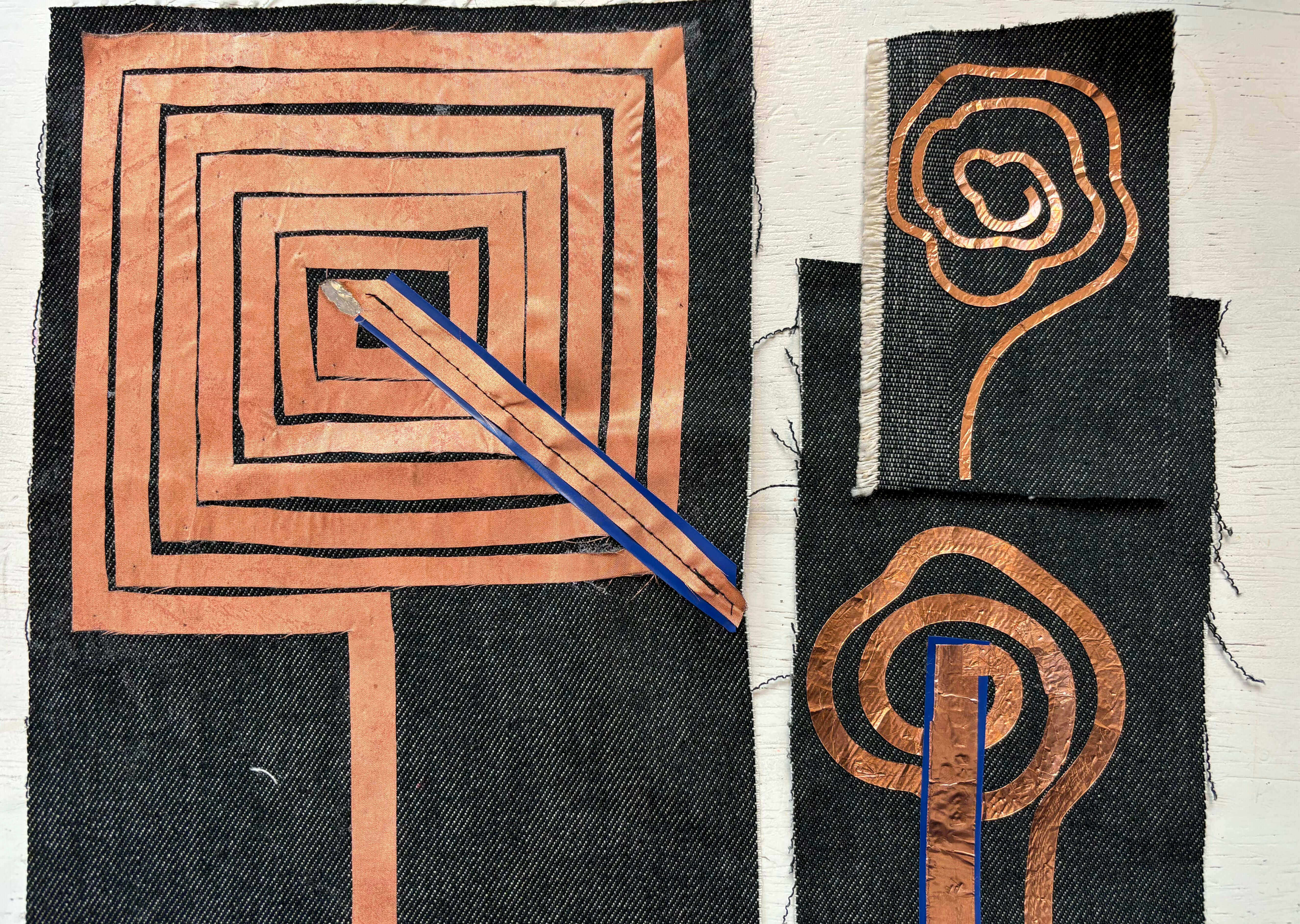
I first drew the spiral on Rhino with the shape of a rose in my mind and ribboned it to get a speaker, and then I saved it into a dxf file and uploaded it onto Cricut Design Space.
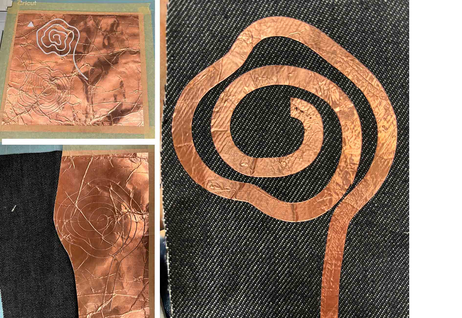
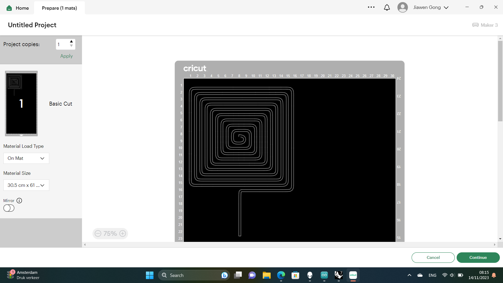
I tried to cut out my first speaker with Cricut Maker 3. The material I used was copper foil with adhesive glue. I thought it would be easier for transfering the speaker onto my fabric later, but it didn't work because the lines were too thin and got tangled in the nozzle.
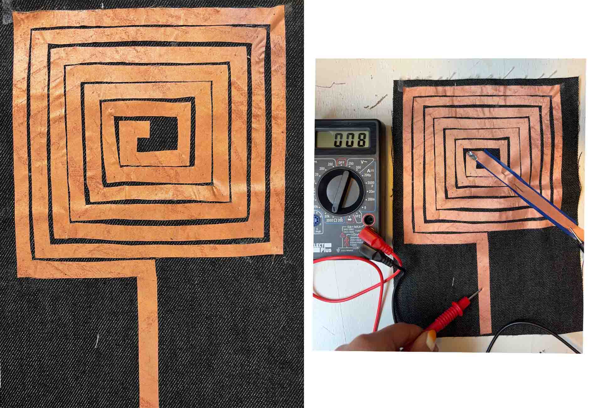
I sketched another model which is wider, and this time it worked with Cricut. But the speaker still didn't work. I tested the connection with a multimeter and realized the electricity doesn't pass through the entire circuit because of the creases on the foil. And this material breaks too easily. So a speaker with copper foil was a bad idea.
2ND SPEAKER
Moving on from copper foil I used a piece of conductive fabric. But the same issue happened when cutting with Cricut.
In the end I decided to it manually...
I glued the speaker onto my fabric with a piece of vliesofix. It was a good idea to pin the speaker in place when ironing.
FINAL SWATCH
A good resistance should be between 4Ω to 8Ω
I don't have a video of it playing music because it requires a big magnet. But during the discussion we thought it can also function as a nice heating pad for experimenting with thermalchromic ink. I will give it a try soon!
FABRICATION FILES
MOTION
DRIVER CIRCUIT
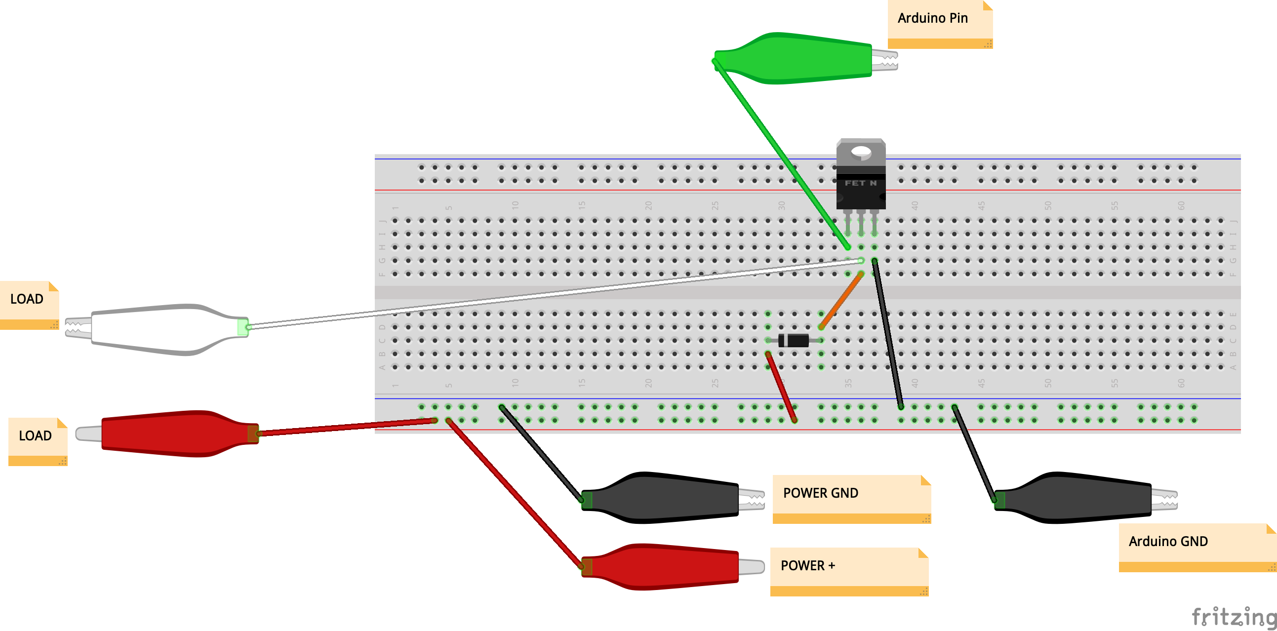
To follow Emma's tutorial on making a flipping wing we first prepared a power circuit.
A driver is a circuit or component used to control another circuit or component.They are usually used to regulate current flowing through a circuit or to control other factors such as other components and some other devices in the circuit. The term is often used, for example, for a specialized integrated circuit that controls high-power switches in switched-mode power converters.
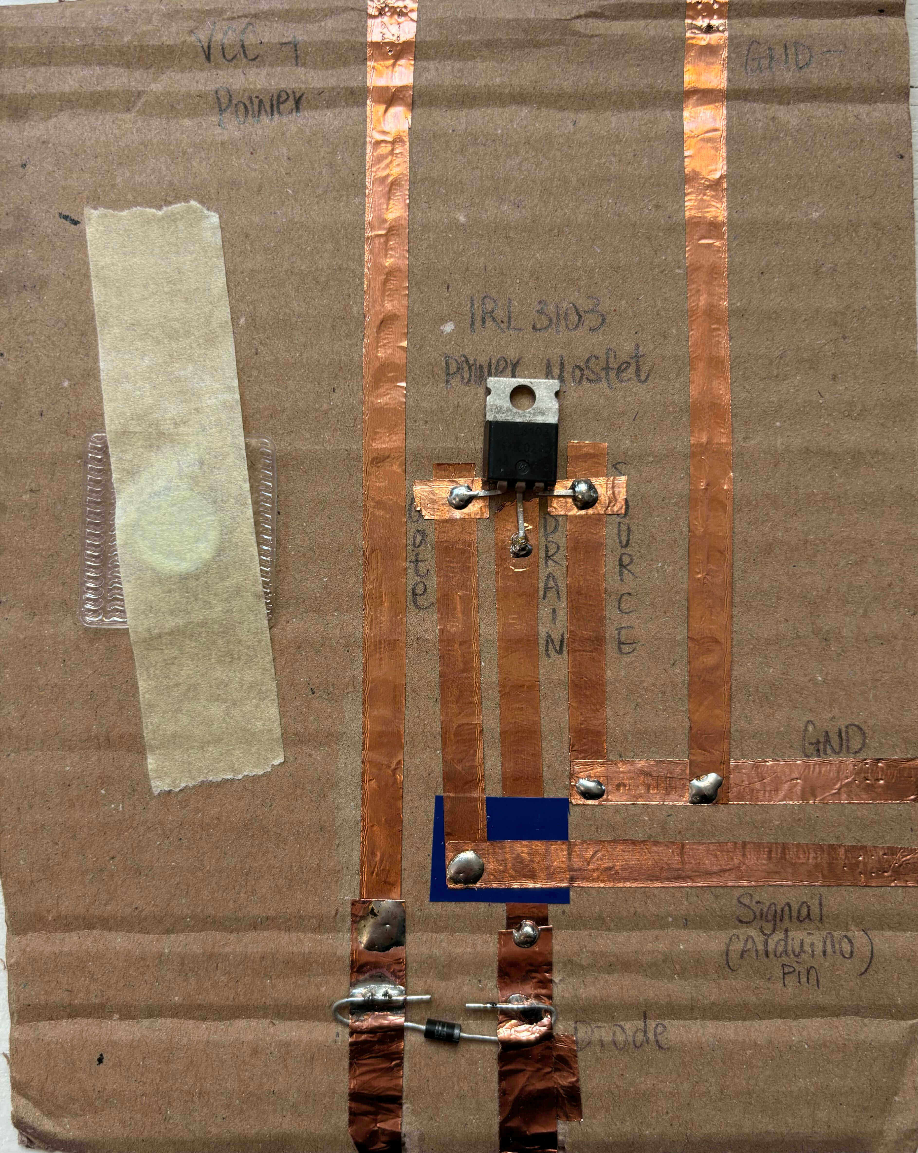
I made a mistake when I was making the circuit. So make sure your diode is put in the right direction.
TOOLS:
- A piece of thick paper or card
- Copper tape
- A piece of regular tape
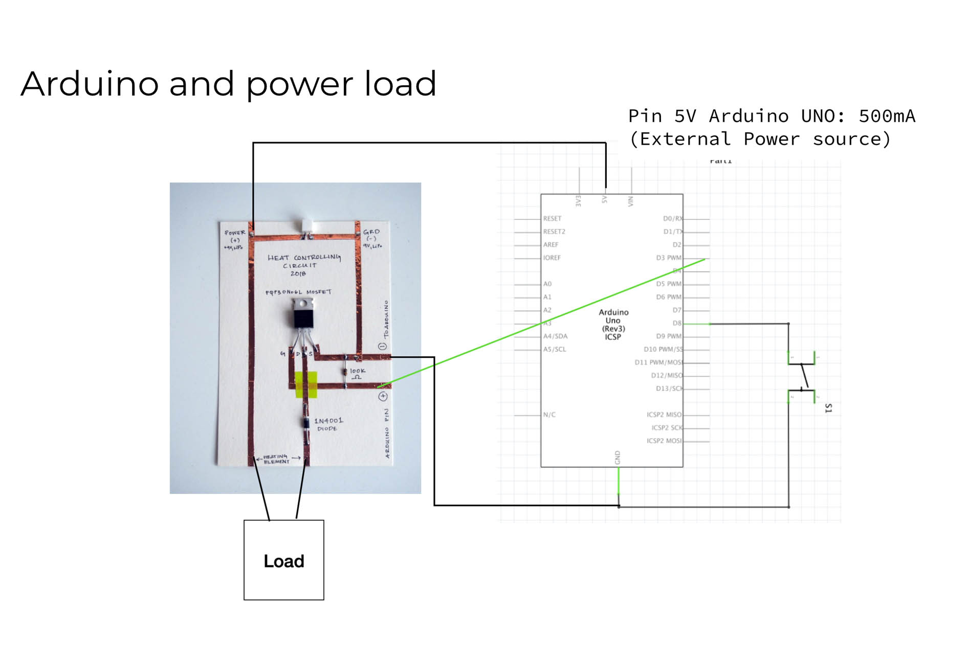
- A MOSFET (ours was an IRF530)
- Soldering iron and solder
- Pliers to bend the legs of the MOSFET
If you don't have the materials to make the driver circuit on the breadboard, you can still build the circuit on the breadboard.
FLIPPING WING
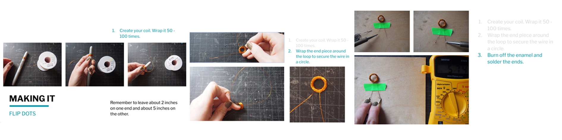
MAKING A COIL (tutorial pictures from Emma's presentation)
CONNECTING YOUR DRIVER TO ARDUINO (tutorial pictures from Emma's presentation)
For a while my coil didn't work and it turned out that the aligator clips could't make enough contact with the wires. So I soldered the wires on another 2 pieces of metal for a better connection.
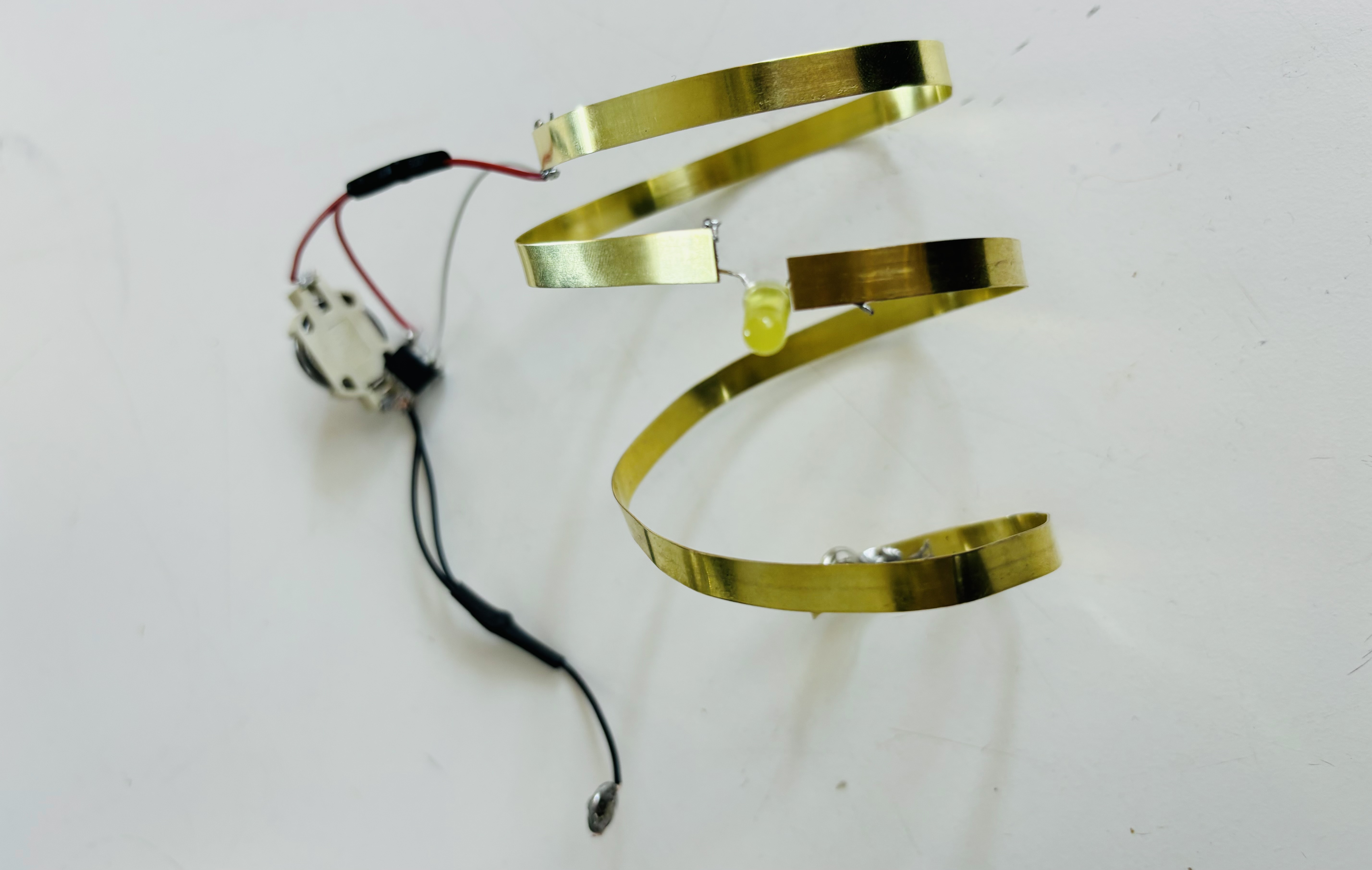
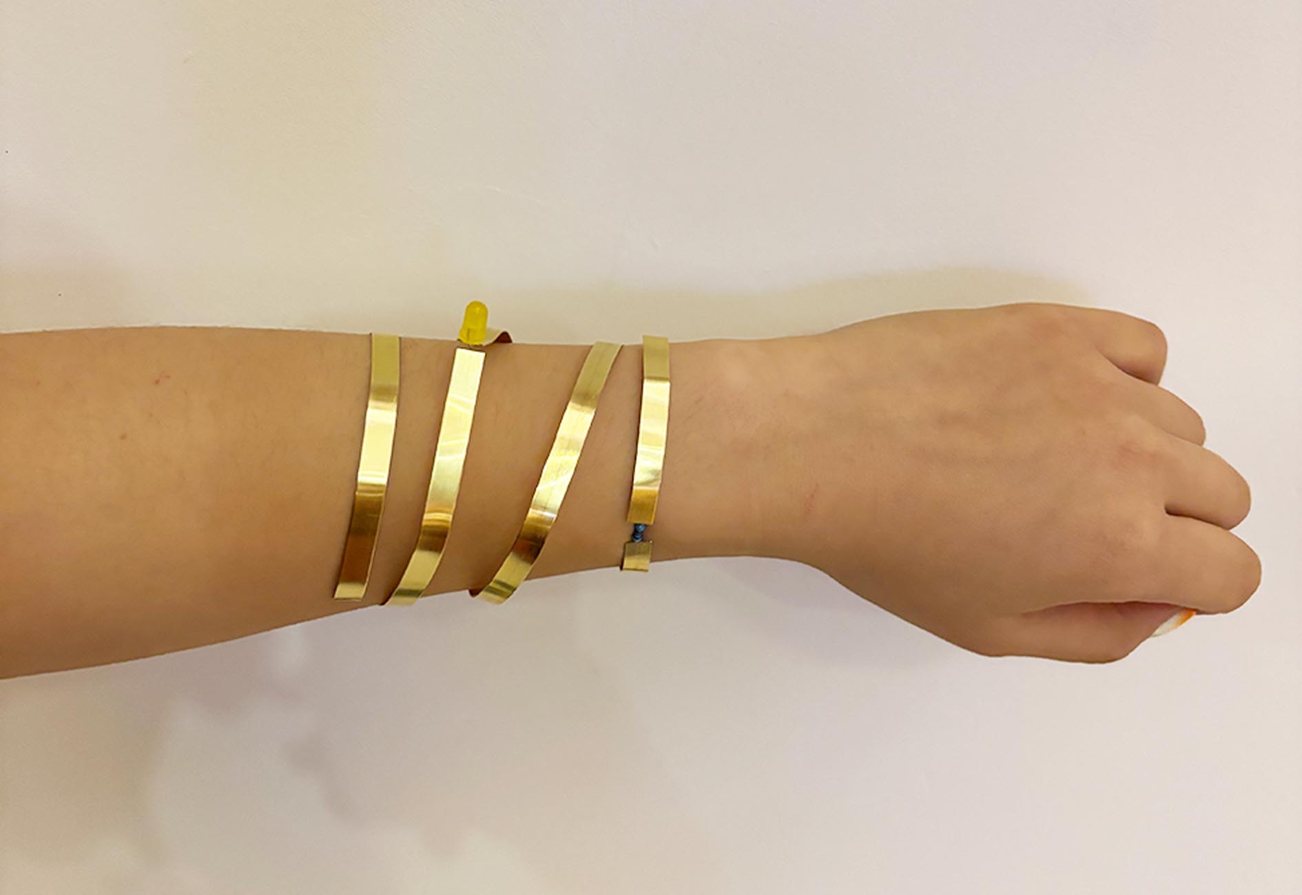
BOUNCING SPIRAL
And the metal pieces gave me the idea to connect my coil to two spiraling copper strips.
MATERIAL
-
4MM Copper Strip
-
Copper wire
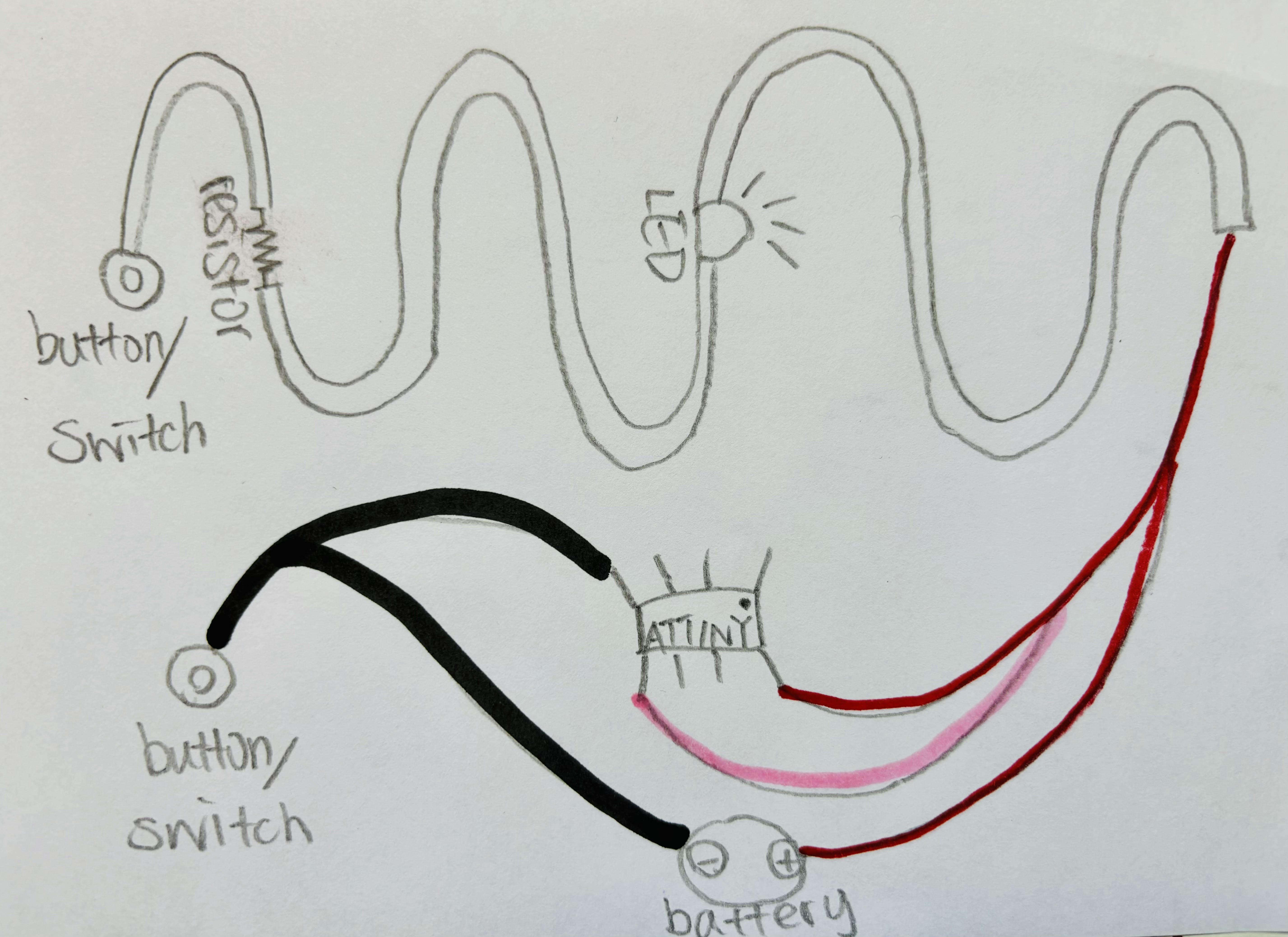
LED
I would like to make a copper bracelet with a blinking led using the ATtiny that I programmed.
MATERIALS
- 4mm Copper Strips
- Snap Buttons
- ATtiny
- 3V Battery
- LED
- SOLER
- Battery socket
- Wires
- Resistor
TOOLS
- Soldering Iron
- Wire Cutter
Making my battery pack for connecting it to my bracelet later.
SCHEMATIC DIAGRAM
I decided to add a digital switch by adding two snap buttons.
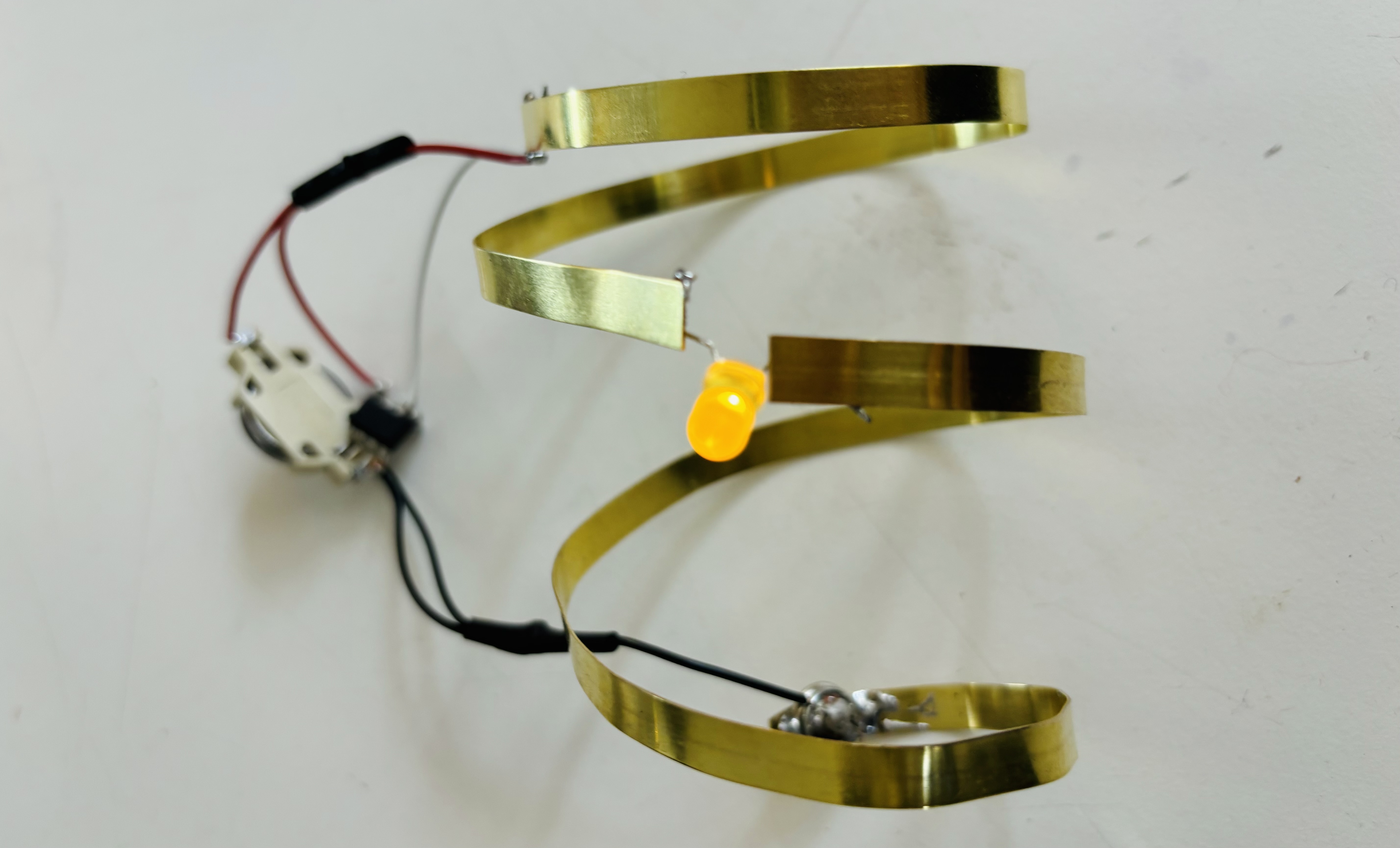
TESTING IT OUT IN THE DARK
I took out the resistor because the LED was giving very dim light. I first thought the resistance was high because the LED was too old, but one of my LED leg broke very soon so I think the high resistance was caused by the almost broken LED light.
Here I broke the leg of the LED during my documentation. I replaced the old LED with a new one and it gives really strong light, so the blinking is less obvious here. I think bringing back the resistor is a good idea now.
POWER ON
POWER OFF