05 E-TEXTILES
RESEARCH
KNITTED KEYBOARD II
TAPIS MAGIQUE
CHROMOSONIC
Chromosonic is an experimental smart textile designed by Hungarian designer Judit Eszter Karpati. It changes colours and pattersn using Arduino open-source platform.
BASIC ELECTRONIC CONCEPTS
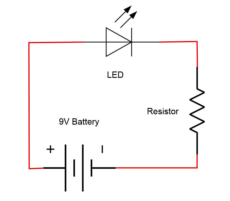
Basic Electronic Circuit
Key Words
Circuit: A complete circular path that electricity flows through.
Current: A flow of charged particles, such as electrons or ions, moving through an electrical conductor or space.
Resistance: A measure of the opposition to current flow in an electrical circuit. Measured in Ohms(Ω).
Trace: A pathway for electricity to flow.
Voltage: THe pressure from an electrical circuit's power source that pushes charged electrons (current) through a conducting loop, enabling them to do work such as illuminating a light.
ELECTRONICAL SYMBOLS AND TERMS
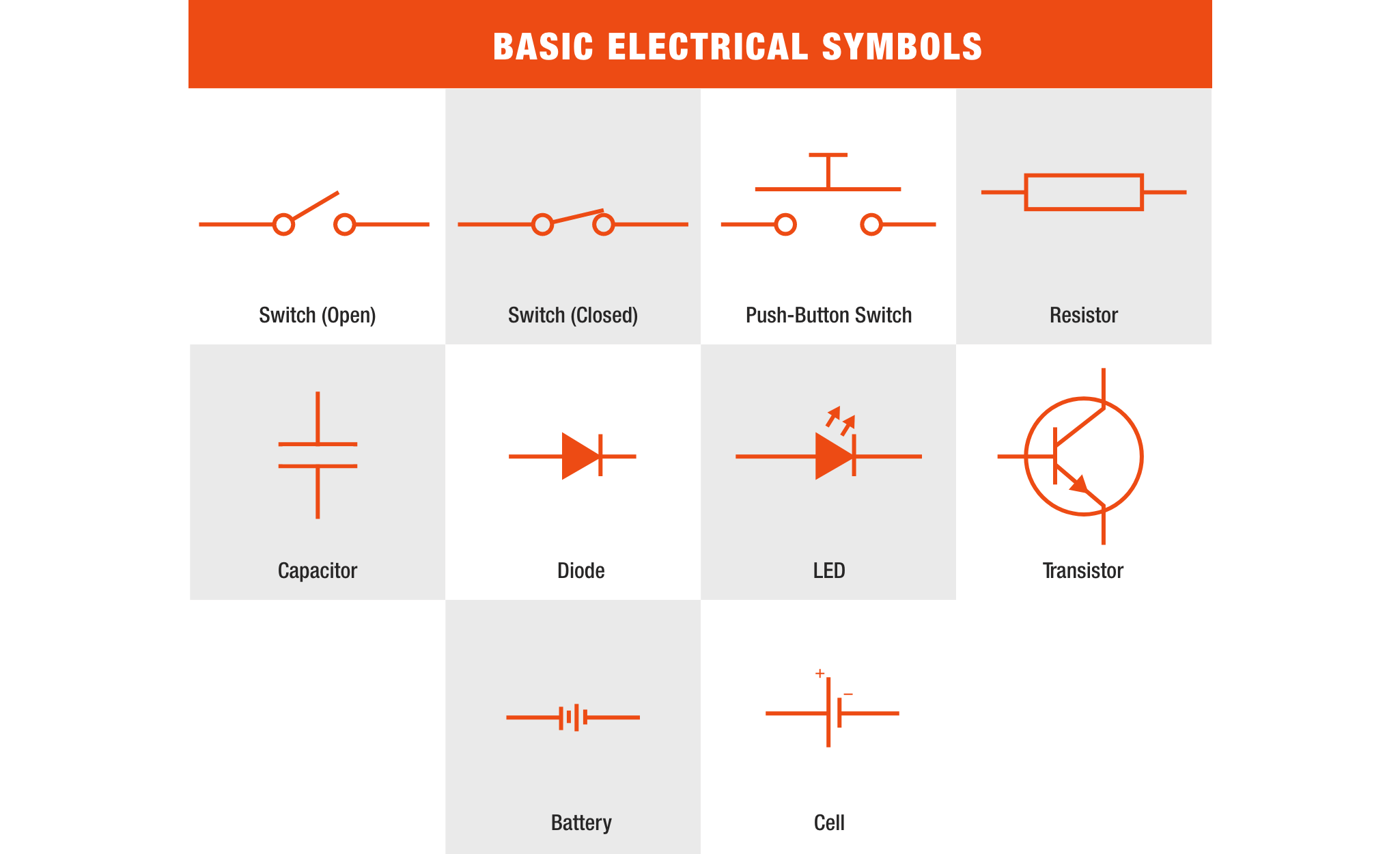
Resister:An electrical device which resists current flow regardless of frequency. Basic unit of measurement is Ohm.
Capacitor: A pair of parallel "plates" separated by an insulator (the dielectric). It stores an electric charge, and tends to pass higher frequencies more readily than low frequencies. Does not pass direct current, and acts as an insulator. Electrically it is the opposite to an inductor. Basic unit of measurement is the Farad, but is typically measured in micro-farads (uF = 1 x 10⁻⁶F) or nano-farads (nF - 1 x 10⁻⁹ F)
Diode: A semiconductor device that essentially acts as a one-way switch for current. It allows current to flow easily in one direction, but severely restricts current from flowing in the opposite direction.
Transistor: A miniature semiconductor that regulates or controls current or voltage flow in addition amplifying and generating these electrical signals and acting as a switch/gate for them.
Cell: one section of a battery.
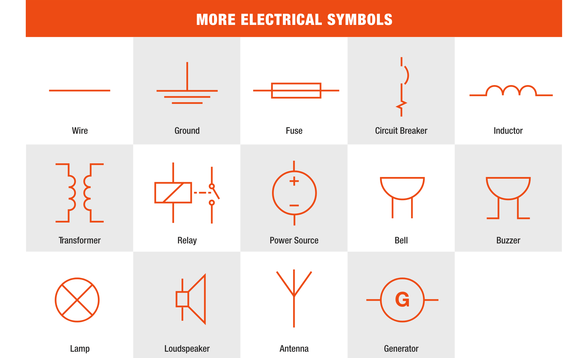
Ground: A reference point that carries a voltage of 0V. Voltage measurements are relative measurements.
Fuse: A safety device that operates to provide overcurrent protection of an electrical circuit.
Circuit Breaker: A switch that automatically interrupts the current of an overloaded electric circuit, ground faults, or short circuits.
Inductor: A coil of wire which exhibits a resistance to any change of amplitude or direction of current flow through itself. Inductance is inherent in any conductor, but is "concentrated" by winding into a coil. An inductor tends to pass low frequencies more readily than high frequencies. Electrically it is the opposite of a capacitor. Basic unit of measurement is the Henry (H), in crossover networks it will typically be measured in milli-henrys (mH = 1 x 10⁻³H) and for RF micro-henrys (uH) are common.
Transformer: A passive component that transfers electrical energy from one electrical circuit to another circuit, or multiple circuits. It steps up or steps down voltage.
Relay: A switch that uses electromagnetism to convert small electrical stimuli into larger currents.
Generator: A machine which transforms mechanical energy or magnetic energy into electric energy.
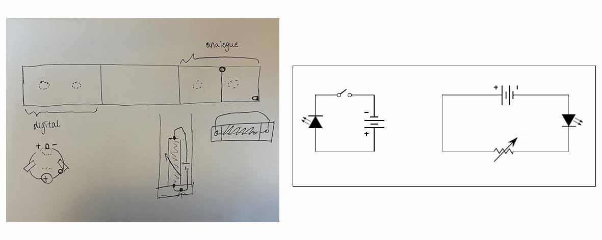
DIGITAL CIRCUIT
Digital Circuit is a circuit where the signal must be one of two discrete levels. It's discontinued and acts like a switch where each level is interpreted as one of two different states,for example, on/off, 0/1, true/false.
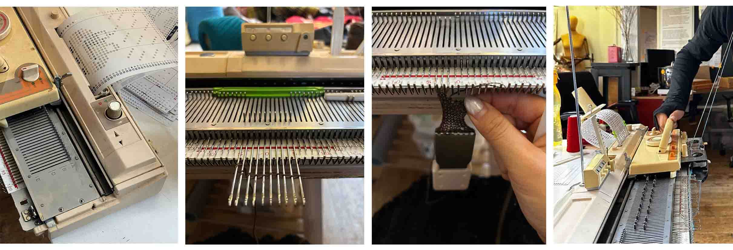
My goal for this week is to make a knitted scarf with the two different types of circuits. For the digital part I knitted it with two regular knitting yarns and a punch card with pattern. The digital circuit will then be added on the scarf. I also knitted two covers to hide the batteries.
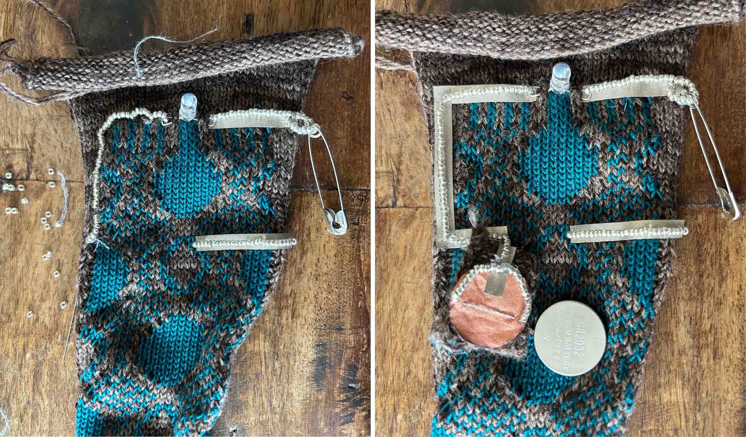
I had multiple fails with creating a path for the electricity to flow smoothly. So for this one I really want to build a strong connection between the LED and the battery. I initially tried with only using the conductive beads and conductive threads. It worked but the resistance was really high, so I tried conductive tape on the other side to see if it would work better, and it did. In the end I made both sides of the circuits combining beads and tape together, and I used a safety as my switch.
FAILED ATTEMPT
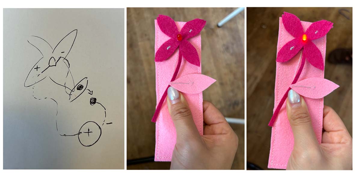
This flower sample was one of my failed samples. I built the circuits with only conductive threads. The problem was that I had to press where I put the battery really hard for the LED to turn on, although my snap buttons (the switch) was closed. I think the reason was because the pink felt fabric I used was quite thick, and the thread was too tight so it went a bit in the fabric, not being able to make contact with the battery properly (short circuit).
ANALOG CIRCUIT
Different from digital circuit, analog signals have continuous electrical signals.
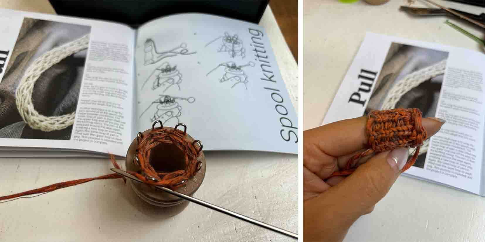
I tried knitting with a knitting nancy, with a regular yarn and a conductive thread. It was not as easy as I thought as the tension was a bit tricky to control. I only managed to knit a tiny bit after half an hour so I switched back to the knitting machine again.
This is a lace knitting sample with a regular knitting yarn and a conductive yarn. But I guess because of the lace pattern (holes) the resistance was really high.
ARDUINO
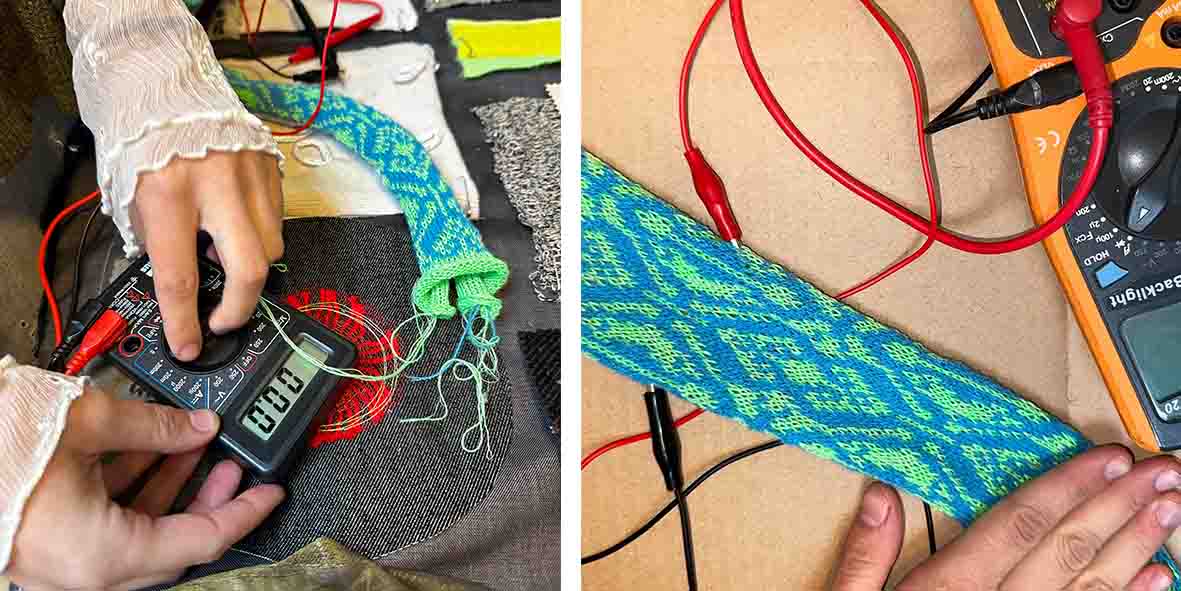
This is a knit sample I worked collectively with Ray and Riley
Pictures by Ray.
Video by Ray.
This is the code we get from the Arduino.
Easiest Code for Analog Read
    // the setup routine runs once when you press reset:
        void setup() {
    // initialize serial communication at 9600 bits per second:
    Serial.begin(9600);
    }

        // the loop routine runs over and over again forever:
        void loop() {
        // read the input on analog pin 0:
        int sensorValue = analogRead(A0);
        // print out the value you read:
        Serial.println(sensorValue);
        delay(100);  // delay in between reads for stability
        }
Modified Resistance Measurement Circuit (with a 9.5k ohm resistor and with custom lower and upper resistance range)
/*
Resistance Measurement - www.circuits4you.com
Reads an analog input on pin 0, converts it to resistance, and prints the result to the serial monitor.
  Using a 9,5k ohm resistor as known resistor
*/
int ledPin = 5;  // LED connected to digital pin 9

    int lowerBoundResistance = 500;
    int upperBoundResistance = 1500;

    // the setup routine runs once when you press reset:
    void setup() {
    // initialize serial communication at 9600 bits per second:
    Serial.begin(9600);
    }

    // the loop routine runs over and over again forever:
    void loop() {
    // read the input on analog pin 0:
    int sensorValue = analogRead(A0);

        // Convert the analog reading (which goes from 0 - 1023) to a voltage (0 - 5V):
        float voltage = sensorValue * (5.0 / 1024.0);

        int resistorvalue = 9500;
        float I = voltage / resistorvalue;
        float VRx = 5 - voltage;
        float Rx = VRx / I;
        Rx = (5 - voltage) / I;

        int mappedValue = map(Rx, lowerBoundResistance, upperBoundResistance, 0, 255);
        mappedValue = constrain(mappedValue, 0, 255);

    // print out the value you read:
    Serial.print("Resistance:");
     Serial.print(Rx);
     Serial.print(" Ohms");
     Serial.print(" and mapped value is ");
     Serial.println(mappedValue);
    analogWrite(ledPin, mappedValue);
     delay(100);
    }
This is an e-textile sample by Michelle Vossen where the closed loop electrical signals send the computer either a keyboard stroke or mouse click signal using Makey Makey.
TOOLS
- Conductive Tape
- Conductive Beads
- Conductive Yarn
- Regular Yarn
- Batteries
- LED
- Knitting Nancy
- Knitting Machine
- Arduino IDE
- Makey Makey