5. E-textiles
Research
In preparation of the Wearables week - "wearables": garments or accessories with embedded electronic devices -, this assignment focuses on learning how to integrate electric circuits in fabric.
At the start of this program, now one month ago, I wrote: "The adventure is: discovering new worlds for me in the form of the beta science community, while crafting beauty for the world to see, and discovering how both my brain and my soul respond to another phase of shape-shifting." This week has been my first actual step towards basic physics principles. I searched in my brain for any useful memories of physics lessons in high school and nothing came up. Zero. Zilch. So, during the lectures and tutorials nothing clicked in my brain. It was merely a vague mush of Ohm's, voltages, conductivity, plusses, minuses, and other stuff that found no home in my neurons. I guess it all comes down to the big - and only - question during this process: does the LED light work or does it not work?
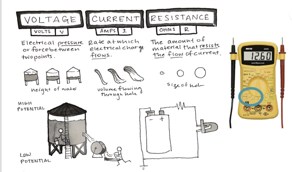
Here are some of the notes that took a long time to make sense to me - and perhaps still don't:

Credit: Liza Stark
Credit: Liza Stark
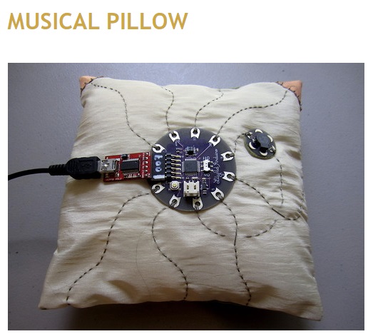
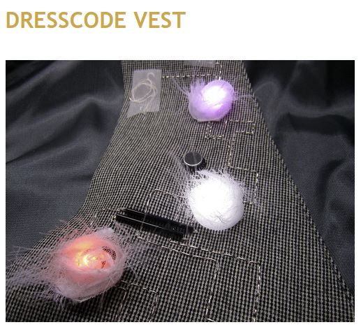
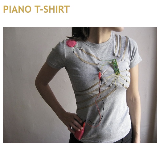
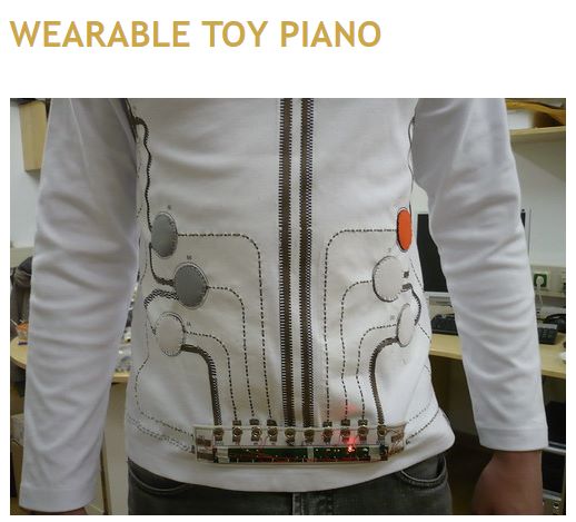
Examples of swatches and garments with integrated circuits:
 |
 |
|---|---|
 |
 |
For this week, I had to build one digital and one analogue soft sensor, using different materials and techniques.
How a digital circuit works
A digital sensor is dichotome, so there are only two options regarding output, such as on or off, no light/light/, sound on/sound of.

Credit: Liza Stark
How an analog circuit works
Analog sensors use varying resistance to get a broader range of values. By varying resistance of your imput -allowing more or less current to get through- you can change the output. Eg. the light will shine brighter or less bright depending on the amount of resistance, or the sound will be louder or less loud.
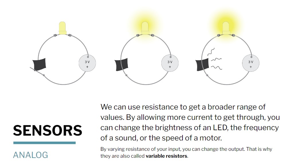
Credit: Liza Stark
Process and workflow
MY BRAIN PROCESS - - - WILL THE LIGHT GO ON?
I did not really understand any of this when I began this momentous task.
Having to build the simplest circuit felt like starting a new job as an engineer at SpaceX, with a law degree.
In the end, I made five swatches:
1 One with beautiful design potential, yet does not work
2 An ugly digital sensor, works
3 A not very pretty analog sensor
4 A nice looking working Book of Light
5 A digital sensor tested for resistance with Arduino (more on Arduino later)
Digital sensor attempt 1
I began the same way as I begin with painting and creative writing. I start by creating chaos and then slowly find my may to something beautiful by adding and substracting things so it eventually 'works'. I call this process 'From Chaos to Beauty'.
I chose a black fabric as a swatch for my first circuit. That fabric itself is not conductive, so I had to integrate conductive material into it, for example by sewing.
These are some examples of fabric or yarn that are conductive.
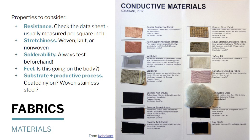
Credit: Liza Stark

Credit: Liza Stark
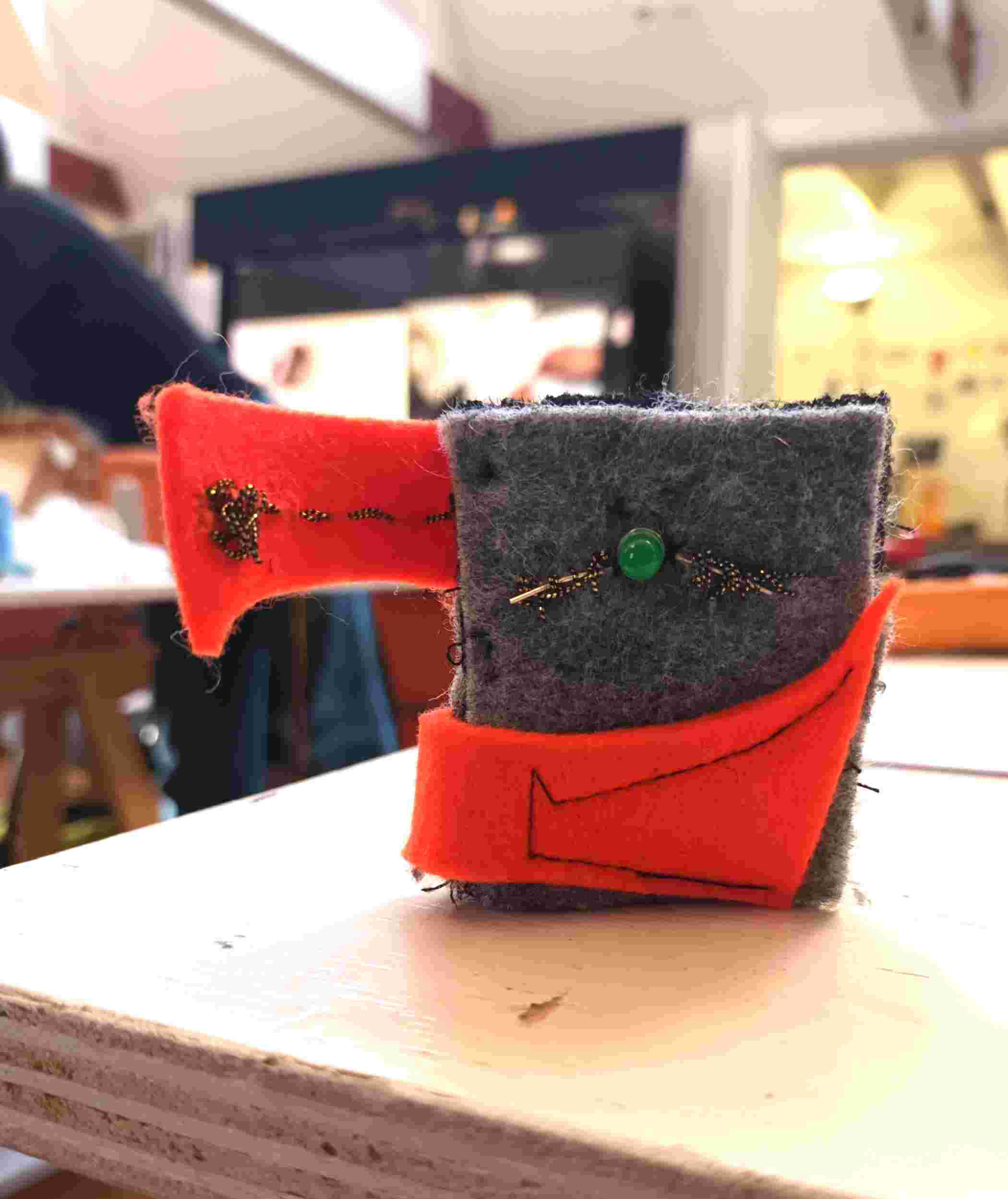
Because I still had no clue how to connect a LED light to a battery in a circuit, that is, in a way that it would actually shine light, I went all out and sewed a whole bunch of tiny strips, squares and dots on my black swatch, using conductive yarn. Then I added a little bit of conductive wool, just for the sake of it, and a book screw, because book screws are way cool.
I tested this design with a multimeter (one of those walkie talkie things with a red and a black wire that sometimes has little crab claws referred to as crocodile teeth), and there was resistance (Ohm) all over the place. This is great, I thought, and the light flickered a bit and then stopped working. Long story short, I wasted two batteries which drained within seconds because of a short in the circuit.
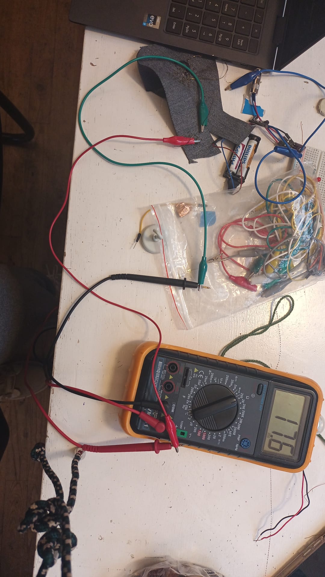 multimeter

Henk the technical guy downstairs patiently tried to help me and in the end we both concluded that I should pause this project and start with something more simple. Apparantly, electricity is 'lazy', flows like water (it goed wherever it can find a way), and I had not so much built a circuit as I did a completely useless thing that would never produce light.

Digital sensor attempt 2
To live is to learn, and because of this failed project I started to think about what I needed to actually make a circuit that works. Our amazing tutor Michelle Vossen had already gave us a drawing of a circuit, but this time I decided to actually look at it. This is the drawing of a circuit:

And I looked at it, and again, and again, and I told my brain to understand it so that I knew what to do.
It was time for my second attempt.
For this second attempt, which I titled 'Pink Toffee', I was inspired by Michelle Vossen's conductive wool swatch. In this swatch, she combined conductive wool with normal wool, and build it into a sensor.

Credit: Michelle Vossen
I used a lot of conductive wool, and made it into a fun chaotic design, and the circuit works, but it is still quite a messy swatch. The horse shoed shape is the circuit, with the open ends connecting to the battery and the LED light.
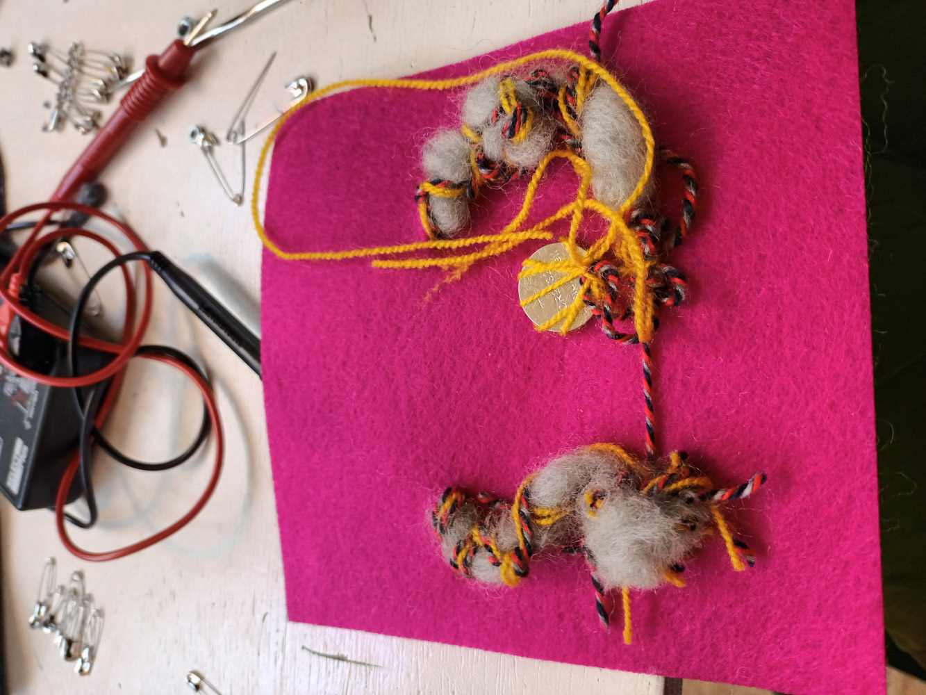
It works, so touché for me and the digital sensor - but I can't say Pink Toffee meets my aesthetic demands.
The analog sensor
I was advised to draw out my circuit before actually making it. This is the drawing I made after I build it and it proved to work, but let's pretend I drew this beforehand.

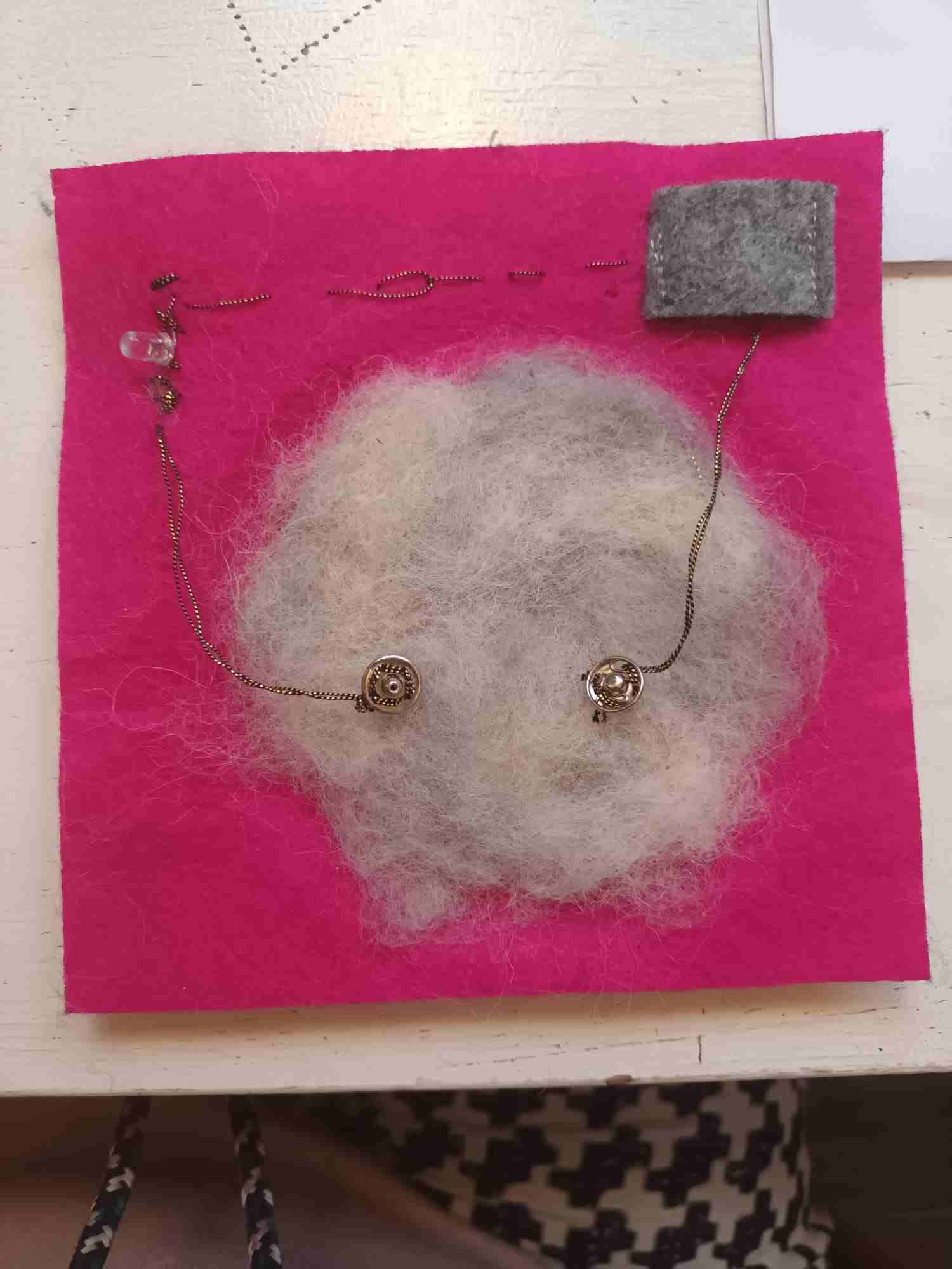
I mixed normal white wool with conductive grey wool by felting. The whole circle is part of the circuit. With both buttons pressed into the wool, the circuit is complete and the light switches on.

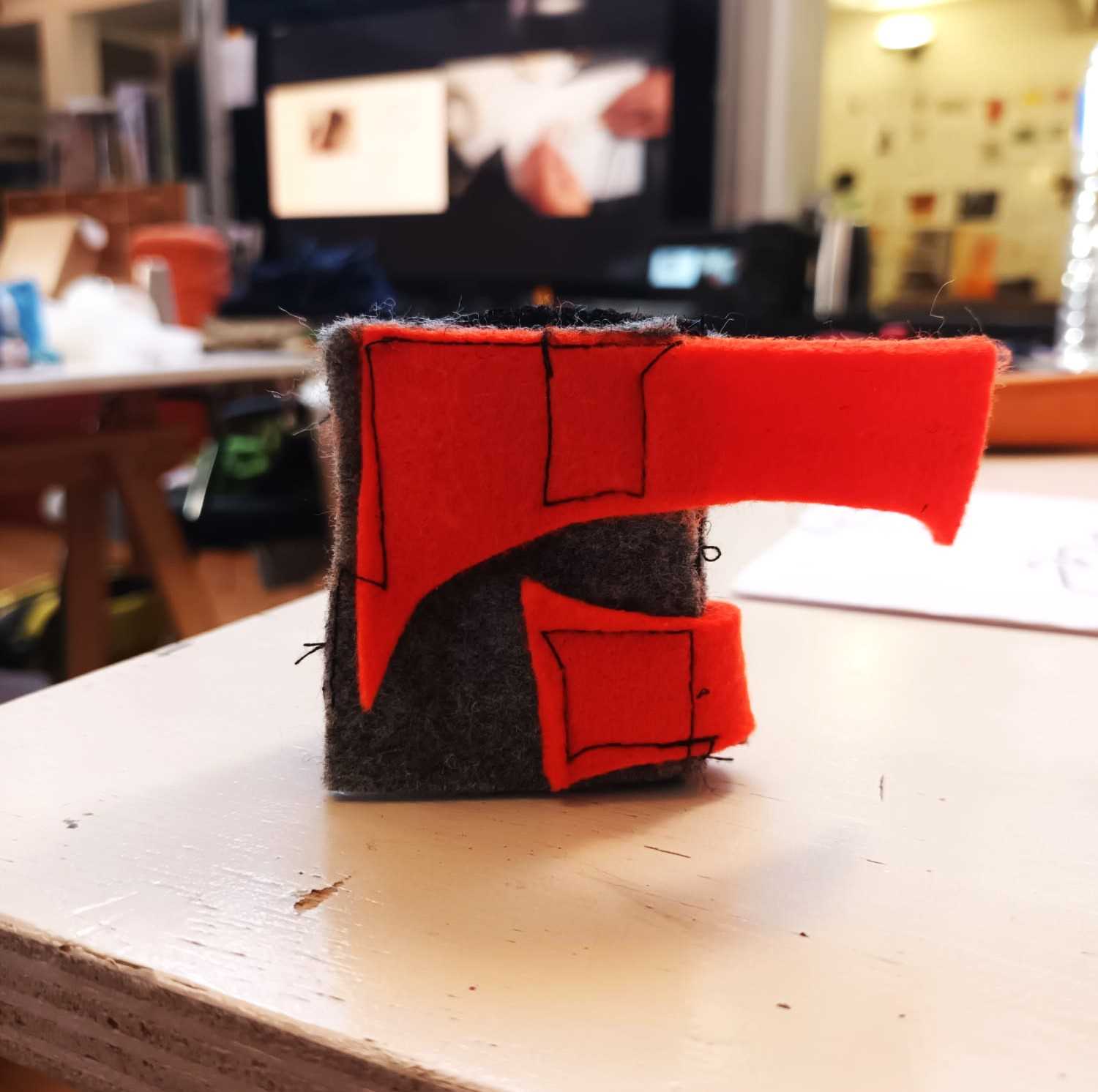
Digital sensor - The Book of Light
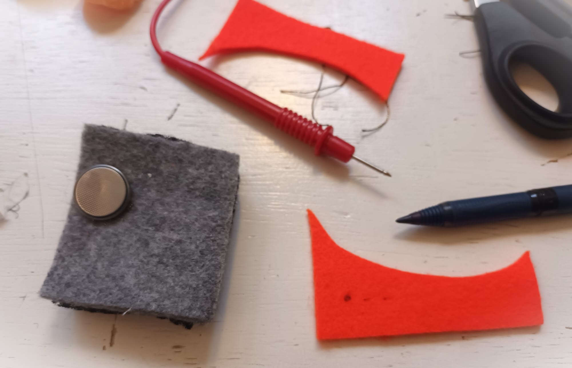
With this Book of Light, the light finally switched on in my head. There is a clear circuit, and a good connection between the battery and the LED light. The 'dust cover' works as the switch, and on the back I sewed in the battery.
Lessons learned: electricity does not like chaos, nor cares about aesthetics.
Arduino
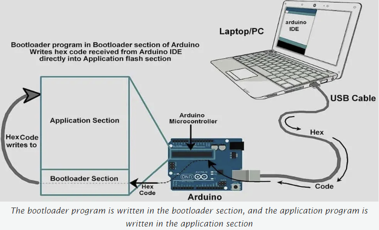 See for a general tutorial on working with an Arduino Board How to setup and burn the Bootloader to any Arduino board
Arduino is an open-source electronics platform based on easy-to-use hardware and software. Arduino boards are able to read inputs - light on a sensor, a finger on a button, or a Twitter message - and turn it into an output - activating a motor, turning on an LED, publishing something online. You can tell your board what to do by sending a set of instructions to the microcontroller on the board. To do so you use the Arduino programming language (based on Wiring), and the Arduino Software (IDE), based on Processing.
(We will use more of this in the Wearables week.)

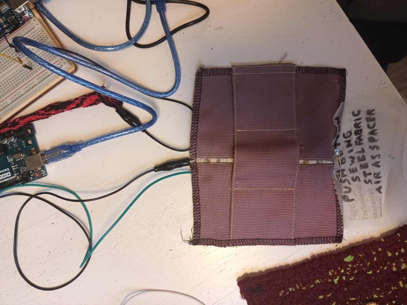
Arduino Swatch
Made a swatch to test the resistance using Arduino.
Inspiration: Michelle's sensor
Credit: Michelle Vossen
My twist to it:
The middle patch with the cross on it has a piece of conductive copper foil sewed into it. When it is pressed on the two copper foil stripes, it makes a circuit. Depending on the amount of pressure used (press lightly, press hard), the value resistance differs. When the circuit is attached to Arduino software, it can read the value.
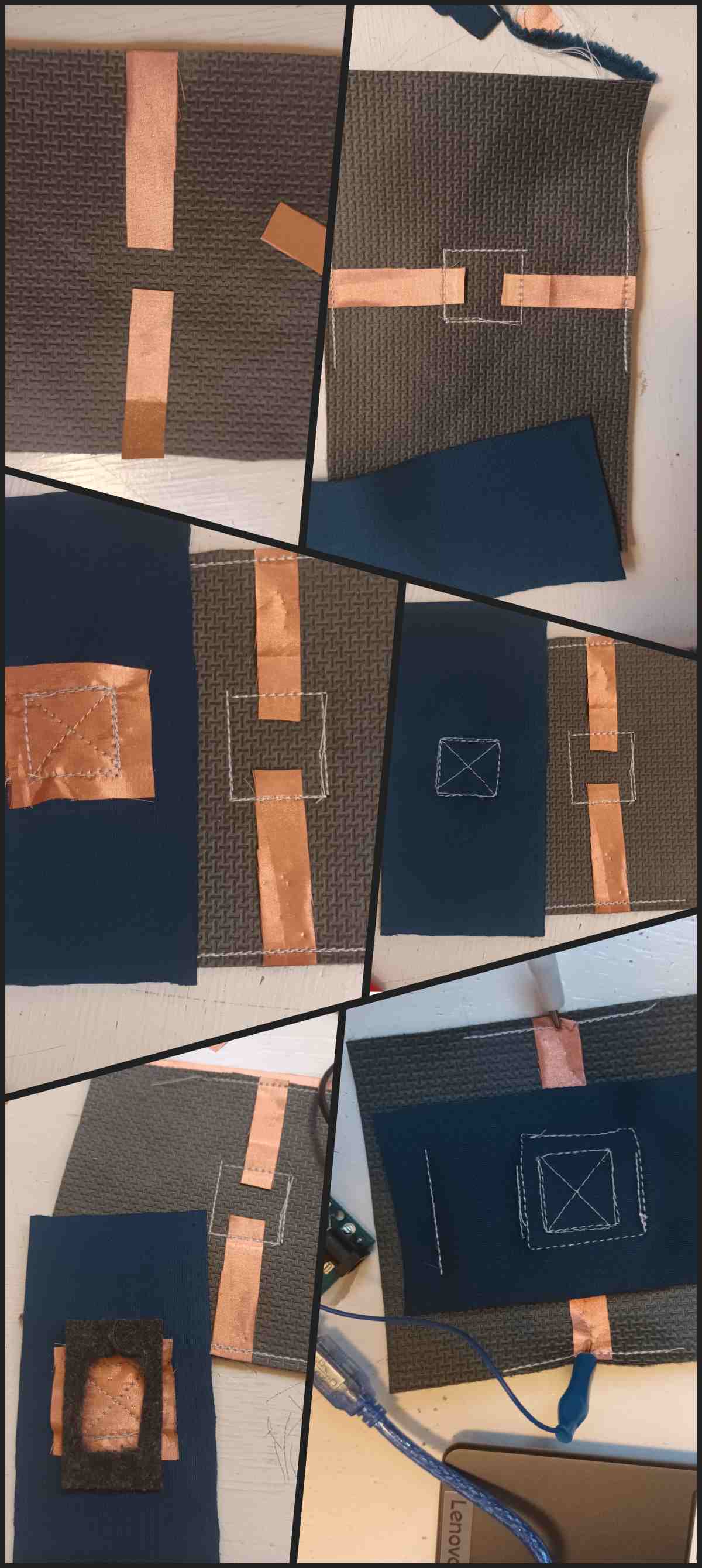
It works!
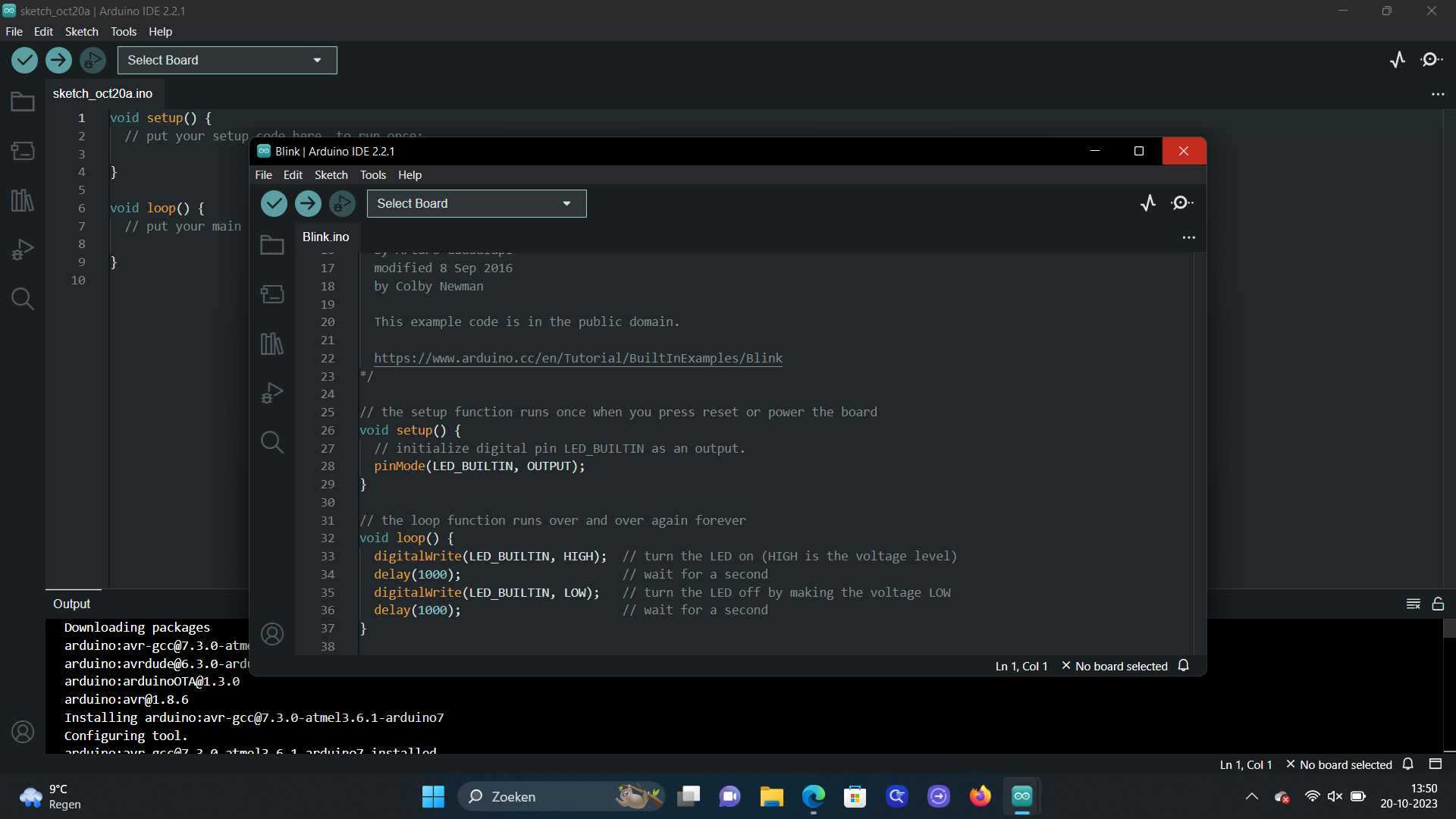
And here is the swatch hooked up to a laptop and the Arduino software, and you can see it shows the amount of resistance:
Arduino Code
Use the three backticks to separate code.
// the setup function runs once when you press reset or power the board
void setup() {
  // initialize digital pin LED_BUILTIN as an output.
  pinMode(LED_BUILTIN, OUTPUT);
}

// the loop function runs over and over again forever
void loop() {
  digitalWrite(LED_BUILTIN, HIGH);   // turn the LED on (HIGH is the voltage level)
  delay(1000);                       // wait for a second
  digitalWrite(LED_BUILTIN, LOW);    // turn the LED off by making the voltage LOW
  delay(1000);                       // wait for a second
}
Tools

Credit: Stephanie Johnson