9. Wearables
Research
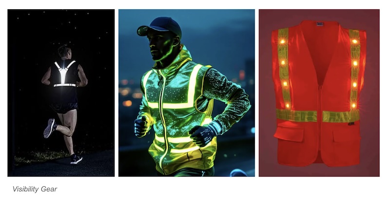
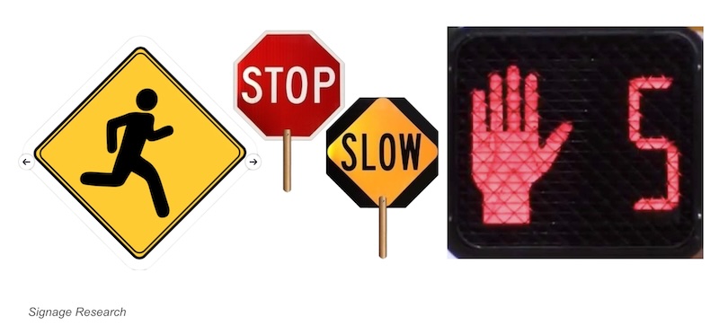
I am interested in using applications from the wearable assignment to solve a very real problem for me around visability when I am walking and running in the evenings. Most of the products available are designed for male bodies and focus on creating reflective surfaces. I am interested in integrating LEDs and incorporating traffic signage into the design. My research included the following links:
References & Inspiration
For this assignment, I had to rely almost entirely on external resouces to teach myself the concepts and skills. Here are the texts and websites that were the most helpful:
-
Kate Hartman's book MAKE: Wearable Electronics This website provides clear step-by-step instructions for how to create the LED actuator. It also does a good job of explaining how the code is written in Arduino.
-
Liza Stark's Computational Craft course. This link supplemented much of the information from Liza's Fabricadmy talk and allowed you the access the links referenced. The YouTube videos linked are much clearer and easier to follow than Zoom recordings. It clarified a lot of my questions around sensors that I had from the Week 5 and I used it for creating the pressure sensor on my STOP mitt.
-
Darcy Neal and Francesca Frattolini's DIY Soft Speakers at the CETI Enchanted Technology E-Textiles Festival. This was a really well done talk and demonstration that focused entirely on the speaker sensors. I wish I had found it earlier in the week. It also referenced a lot of successful applications of the concept that were not covered in the Fabricademy content.
I also had amazing assitance this week from former student and interactive sculptor Genevieve Hildebrand-Chupp
Tools
- Fabrics: Black duvetyne, silk habotai,heat transfer vinyl, polyester batting
- Adafruit Circuit Playground Express
- Conductive Thread
- Sewable and pin LEDs
- Batteries: 9 volt and 3 x AA Battery pack
- Arduino IDE
Process and workflow
LED Actuator
Below is the LED Actuator I created using the step-by-step tutorial in Kate Hartman's book MAKE: Wearable Electronics. I initially planned to use this as the flashing light for my STOP mitt, but it ended up being too bulky to fit on the palm of the glove.
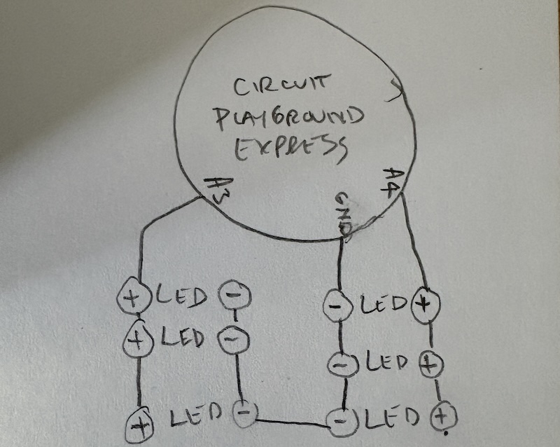
Here are the different images and videos from the different code variations I used to program the microcontroller. The value of the delay entry was what controlled the speed of the flashing from one side to the other.
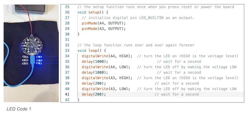
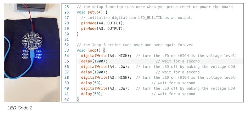
Below is the code for the blink sequence I created for the actuator. I followed the tutorial in Kate Hartmans book for programming the code into the microcontroller using Arduino.
// the setup function runs once when you press reset or power the board
void setup() {
  // initialize digital pin LED_BUILTIN as an output.
  pinMode(A4, OUTPUT);
  pinMode(A4, OUTPUT);
}

// the loop function runs over and over again forever
void loop() {
  digitalWrite(A4, HIGH);   // turn the LED on (HIGH is the voltage level)
  delay(1000);                       // wait for a second
  digitalWrite(A4, LOW);    // turn the LED off by making the voltage LOW
  delay(1000);                       // wait for a second
    digitalWrite(A3, HIGH);   // turn the LED on (HIGH is the voltage level)
  delay(50);                      // wait for a .05 second
  digitalWrite(A3, LOW);    // turn the LED off by making the voltage LOW
  delay(50);                      // wait for a .05 second
}
Speaker Actuator
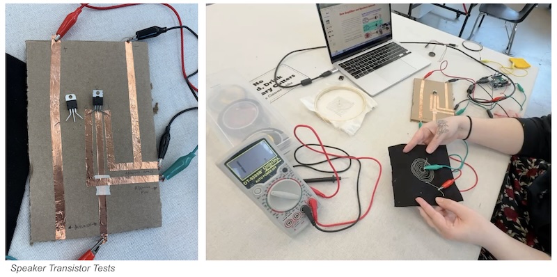
For this part of the assignment I started by creating the MOSFET circut from the class demonstration. Below is a image of what I prepared:
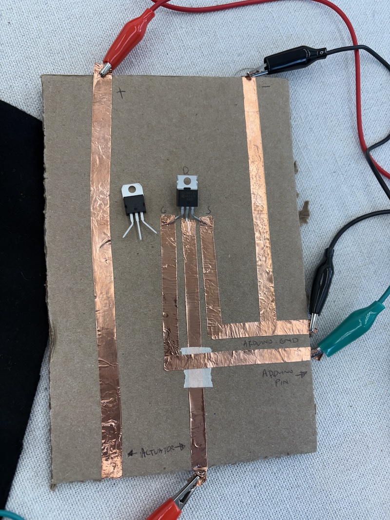
From there I created two speaker options to test relying on images from Liza Stark's presentation materials.
The stitched speakers were created using conductive thead in the bobbin. The silk habaotai speaker was stretched using an embroidery hoop in order to withstand the thickness of the conductive thread.
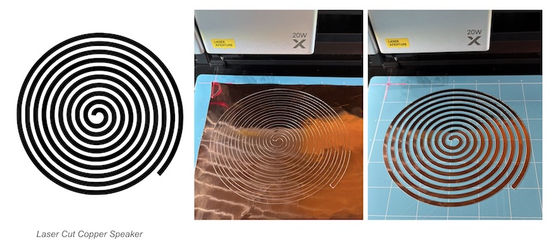
The spiral speaker 1 was created using Inkscspae and laser cut our of adhesive backed copper tape on Xtool vinyl cutter.
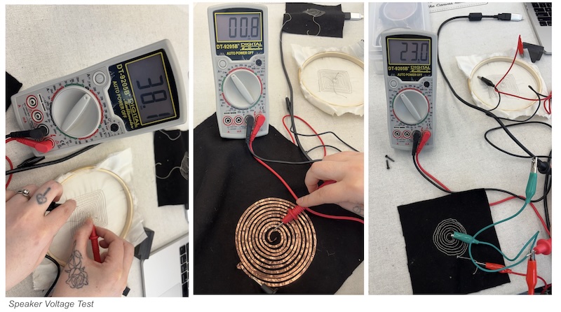
The tutorial for this exercise was very difficult to follow because of the tiny Zoom window. I reached out on Mattermost to for assistance and tried the code from Emma Pareschi tutorials from 2023 shared by another remote student Emma Yanez. Below is an image from the Mattermost conversation for reference and the code used for the speaker test:
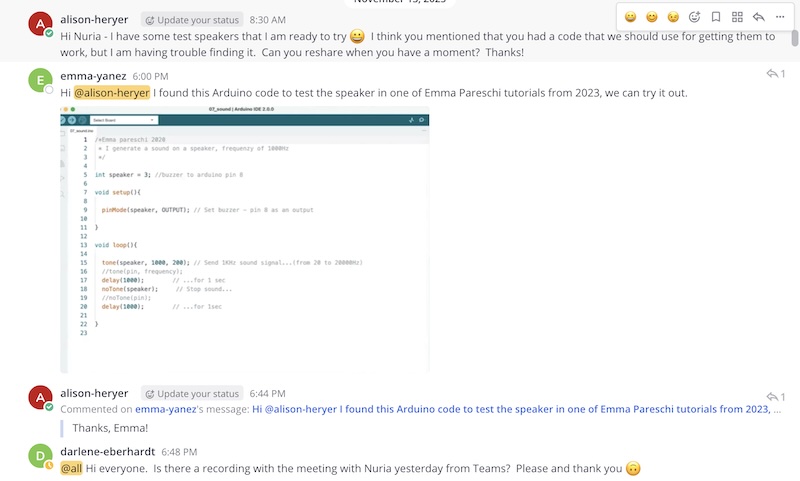
/*Emma pareschi 2020
* I generate a sound on a speaker, frequenzy of 1000Hz
*/

int speaker = 3; // buzzer to arduino pin 8

void setup() {

pinMode(speaker,OUTPUT); //Set buzzer - pin 8 as an output
}

void loo (){
  tone(speaker, 1000,200); // Send 1KHz sound signal... (from 20 to 20000Hz)
  //tone(pin, frequency)'
  delay (1000);   //... for 1 sec
  noTone(speaker);   // Stop sound...
  //noTone(pin);
  delay(1000); // ...for 1sec
}
Below is the schematic used from Liza Stark's to wire the speakers to connect the speaker to the MOSFET, battery, and microcontroller.
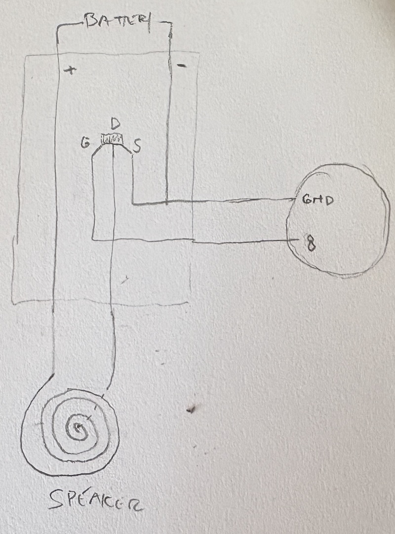
Unfortunatley we were never able to get the speakers to work and there was not time to address the issue in our weekly check in. Below are video links to our tests:
- Speaker Test 1
- Speaker Test 2
- Speaker Test 3
Haptic Actuator
After spending most of the weekend trying to get the speaker to work, we pivoted to the haptic acutator hoping for a win. Below is a video of our test and our buzzing be swatch that we created.
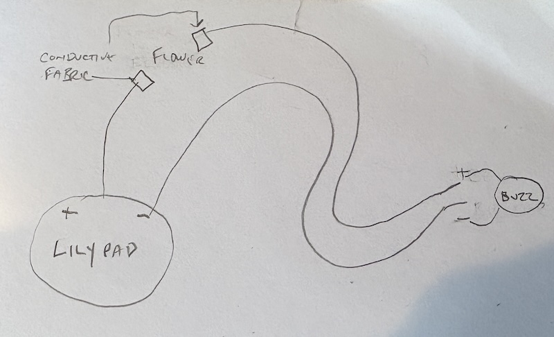
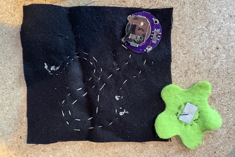
I used a Lilypad Coin Cell Battery Holder for the swatch. There was no code associated with this swatch.Here is the schematic we used to wire the haptic as well as the image of the back of the swatch showing the stiching paths. *We were not really referencing anything specific - just applying the information covered in Kate Hartman's book MAKE: Wearable Electronics
Wearable Project
For the wearable project, I wanted to create something that I could wear when running and walking at night that would get cars to stop at cross walks. Building on the discoveries from the wearable I created in Week 5, I created a mitt that could slide over either my bare hand or a glove depending on the weather. I used an Adafruit Circuit Playground Express microcontroller to create an illuminated STOP sign on the palm that could be activated with the thumb using an analog pressure sensor.
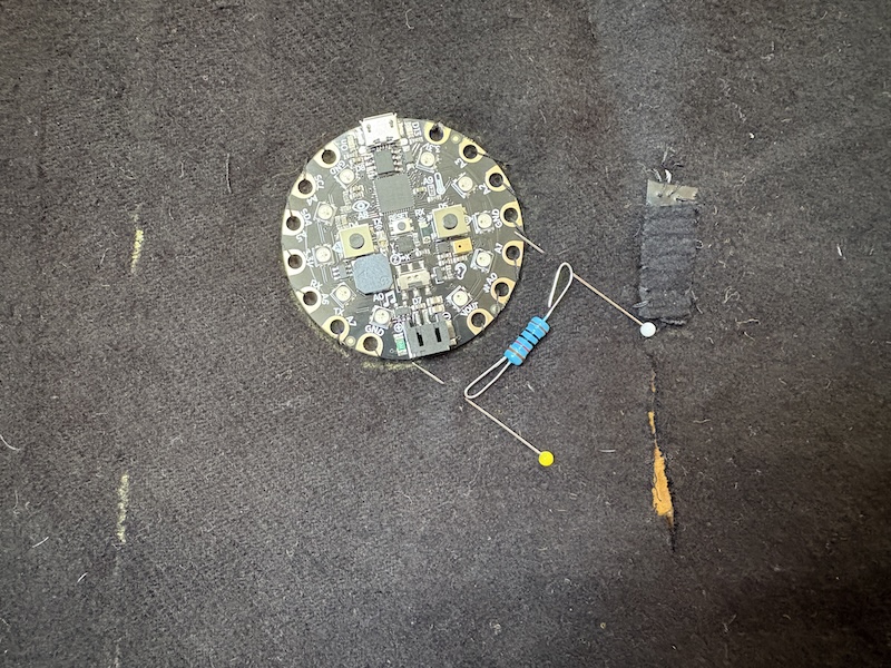
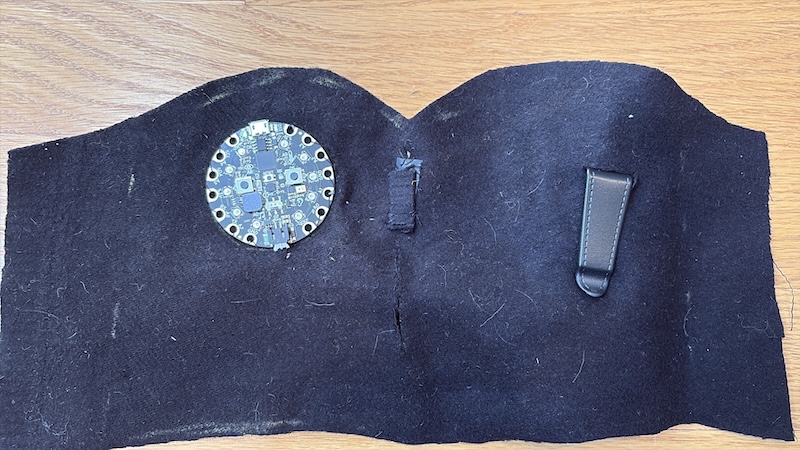
I started by dissambling a swatch from Week 5 to figure out the shape of the mitt and the placement for the microconroller and sensor.
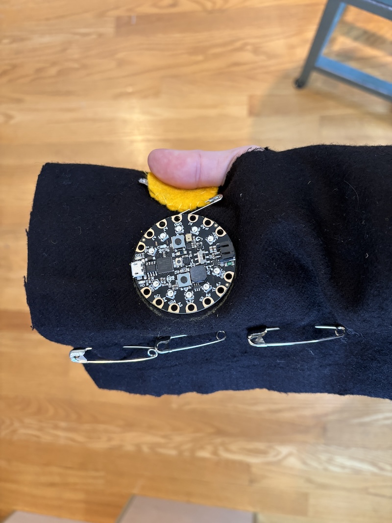
The sensor was created using two thin rectangular strips of conductive fabric. The high side of the sensor was stitched directly onto the outside of the mitt. The conductive material for the signal side of the sensor was attached to a thin strip of duvetyne then threaded to the underside of the mitt just above the thumbhole.
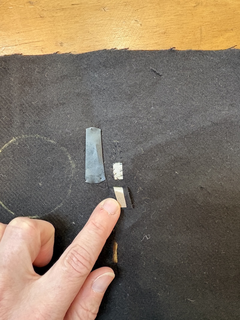
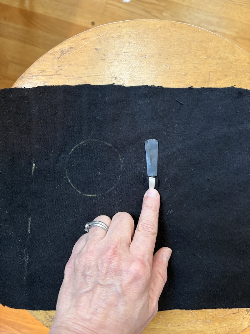
I created the following diagram to track the connection paths on the front and back side of the glove.
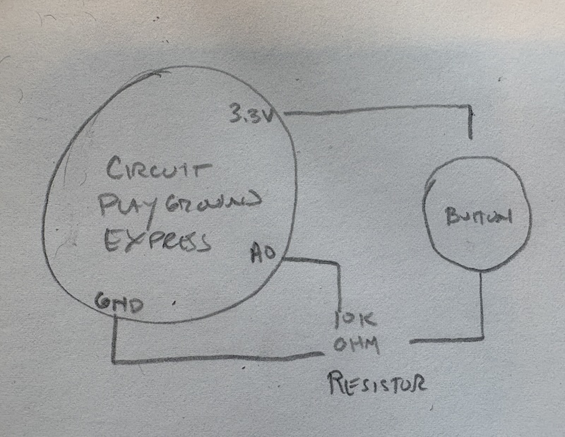
I placed the resistor as close to the microcontroller as possible so the hardware was as close to the flat part of the palm as possible. I stitched conductive thread on the inside of the glove to connect the high side of the sensor to pin 3.3V. One side of the resistor is connected to the signal side of the sensor and pin A1. The other side of the resistor is connected to the GND pin.
I used this conversation with Google Gemeni to reprogram the microcontroller so that the lights lit up red when pressure was applied to the sensor. Below is the video of uploading the code to the microcontroller and the code that was used:
#include <Adafruit_CircuitPlayground.h>

const int sensorPin = A1;
int sensorValue = 0;
int brightness = 0;

void setup() {
  CircuitPlayground.begin();
  Serial.begin(9600);
}

void loop() {
  // 1. Read the pressure
  sensorValue = analogRead(sensorPin);

  // 2. Calculate brightness (using your 720-1000 range)
  brightness = map(sensorValue, 720, 1000, 0, 255);
  brightness = constrain(brightness, 0, 255);

  // 3. Light up RED
  for (int i = 0; i < 10; i++) {
    CircuitPlayground.setPixelColor(i, brightness, 0, 0);
  }

  delay(10);
}
Once the code was uploaded I tested the sensor on the hand to ensue it was working before applying the STOP Sign applique:
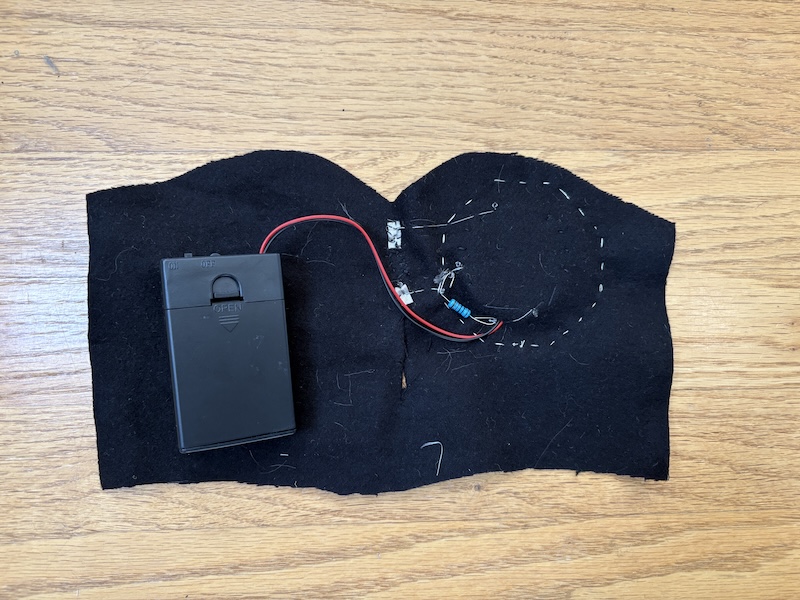
After the successful test, I had to figure out the battery pack placement. This was difficult because it was so bulky. The back of the hand was the most comfortable, but not ideal. I used slits beneath the microcontroller and on the back of the mitt to connect and secure the battery pack. The thickness of the pack also imacted the placement of the lights on the palm. If I ever revisit this project, I would make sure to account for the battery pack when marking the placement of the microcontroller.
Below are images of the front and back of the mitt to show the placement of the elements and wiring"
For the STOP sign applique, I use an Xtool M1 Ultra to cut the red vinyl and ironed it on to muslin.
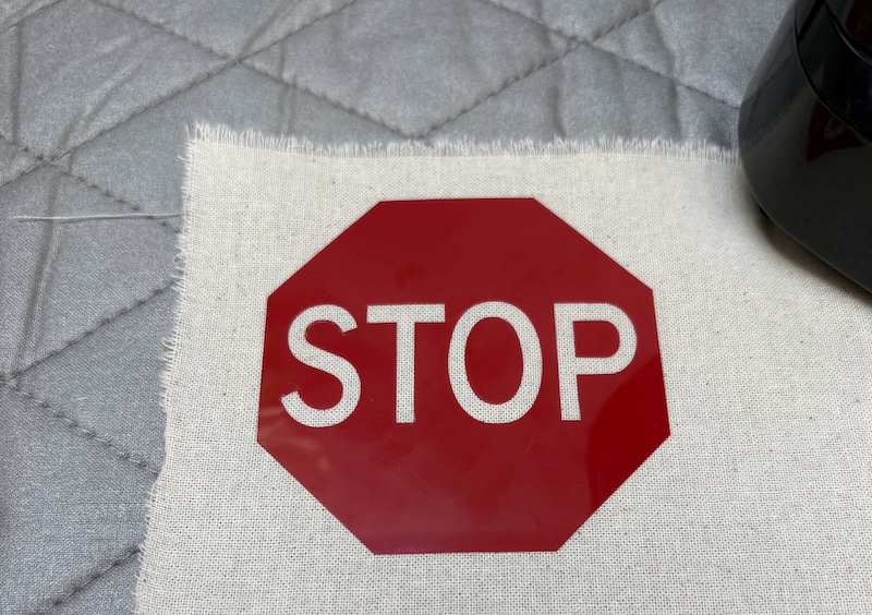
The applique was stitched over the microcontroller and the mitt stitched together on the outside of the palm. Below are images of the wearable in flat view and on the body.