5. E-textiles
Research

Those image shows an early exploration of e-textiles, focusing on how electronics can be integrated into fabric. You can see a combination of textile materials and conductive elements such as threads, sensors, and small components. The setup highlights how soft materials can host electronic circuits, enabling interaction through touch, movement, or embedded light. The visual arrangement suggests an experimental approach: testing connections, understanding how fabric behaves with electronics, and learning how to embed technology inside wearable or flexible materials.
References & Inspiration
These references helped me understand how other designers integrate electronics into soft materials, especially how they hide components, design aesthetic circuit paths, and combine craft with technology.
- Two images side-by-side


- reference
Tools
. Soldering iron (25–40W is enough)
. Solder wire (lead-free or normal 60/40)
. Soldering stand
COMPONENTS NEEDED
- Red LED / Red Bulb
3V to 5V LED (common red LED)
- Resistor
220Ω (ohm) resistor (protects the LED from burning)
- Power Source
Battery 3V coin cell
Battery holder
- Wires
Small connecting wires
Process and workflow
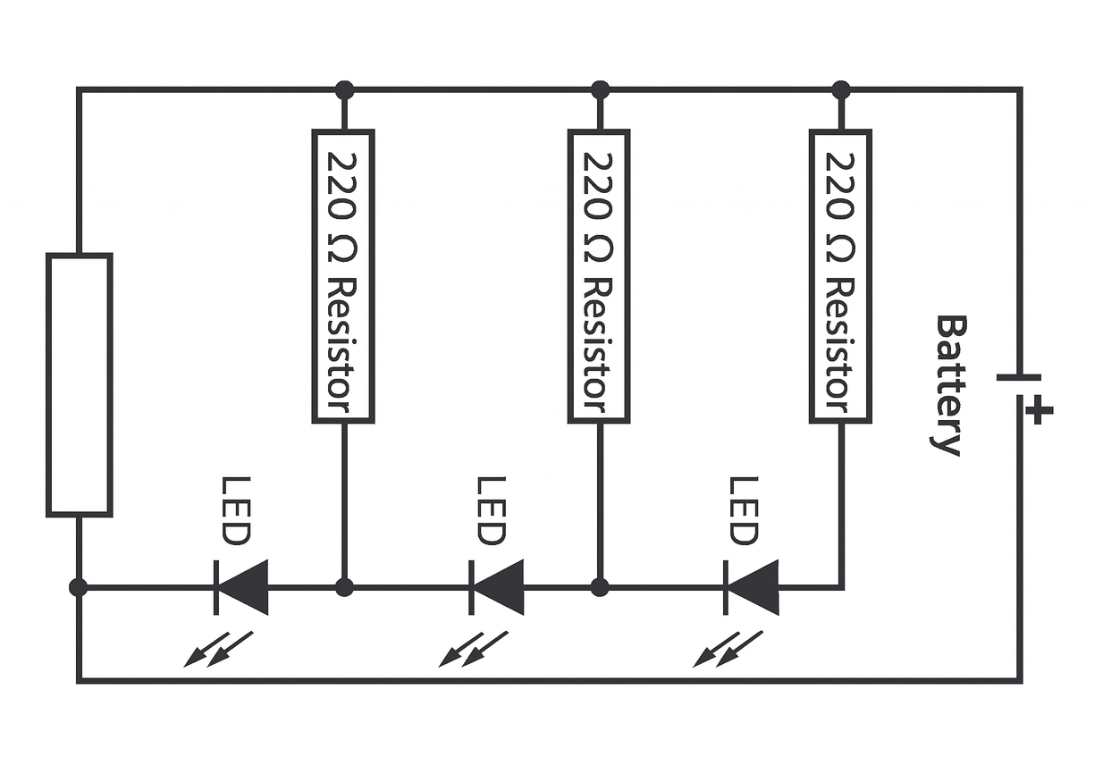
🔧 1. Collecting Tools and Materials To create the circuit with four LEDs, I prepared the following tools and components: • 4 Red LEDs • 4 Resistors (220Ω each) • 1 Battery 3Vwith a battery holder • Soldering iron • Solder wire • Connecting wires • Wire stripper • Electrical tape / heat-shrink tube
🔧 2. Preparing the LEDs
Each red LED has two legs: • Long leg — Positive (+) • Short leg — Negative (–) I first separated all four LEDs and identified their positive and negative legs.
🔧 3. Adding Resistors
To protect the LEDs from burning, I connected one 220Ω resistor to each LED. • I twisted one end of the resistor onto the long leg (positive) of each LED. • Then I soldered the connection to make it strong and stable. This means each LED now has its own resistor, which ensures equal brightness and safety.
🔧 4. Creating the LED Circuit Layout
After attaching the resistors, I arranged the four LEDs in the layout I wanted. You can arrange them: • In series (one after another) • In parallel (all positive together, all negative together) ⭐ For bright and stable light, I connected them in parallel.
🔧 5. Connecting the Positive Side
I joined the free end of all four resistors together and connected them to the positive wire (red wire) from the battery holder. • I soldered the joint • Covered it using electrical tape / heat-shrink
🔧 6. Connecting the Negative Side
I connected all negative legs (short legs) of the LEDs together. Then I soldered a black wire from the battery holder to this negative joint.
🔧 7. Insulating the Circuit
After all soldering was complete, I covered: • Exposed metal • LED joints • Wire joints Using heat-shrink tubing and electrical tape to avoid short circuits.
🔋 8. Powering the Circuit
Finally, I placed the battery in the holder. If connections are correct: ✅ All four LEDs light up smoothly ✅ Brightness is equal ✅ No flickering
My sketches are ...
Results
1ST WAY
SECOND WAY
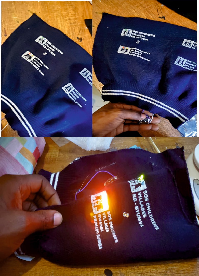
Soft Sensor Zip
Tools & Materials Zip (attached to fabric) LED Coin cell battery (3V) Conductive thread / copper tape Fabric
⚙️ How It Works
This is a basic circuit:
Battery → LED → Zip → back to battery
👉 The zip acts as a switch:
CLOSED (right side) → electricity flows → LED ON OPEN → no connection → LED OFF
Process & Workflow
Step 1: Preparing My Zip I attached the zip to fabric I focused on the right closing side as the trigger
Step 2: Creating Conductive Paths
I used conductive ZIP TEEH One side connected to: Battery (+) Other side connected to: LED
Step 3: Using the Zip as a Sensor I positioned conductive parts so that: When the zip closes → they touch When open → they separate
👉 This turns the zip into a soft switch sensor
Step 4: Completing the Circuit I connected: Battery → LED → Zip → Battery
Experimentation
I tested opening and closing the zip I adjusted the contact points Observations: Full closure → strong light Partial closure → weak or no light
✅ Results The LED turned ON when I closed the zip on the right side
2ND way
Tools AND workflow
1️⃣ Tools & Materials Needed Electronics
1.Arduino Uno or Arduino Nano
2.MPU-6050 sensor module
3.flexible silicone
4.3 × 220Ω resistors
5.Breadboard
6.Jumper wires
7.USB cable
8.Software
9.Arduino IDE
“MPU6050” library (installed from Library Manager)
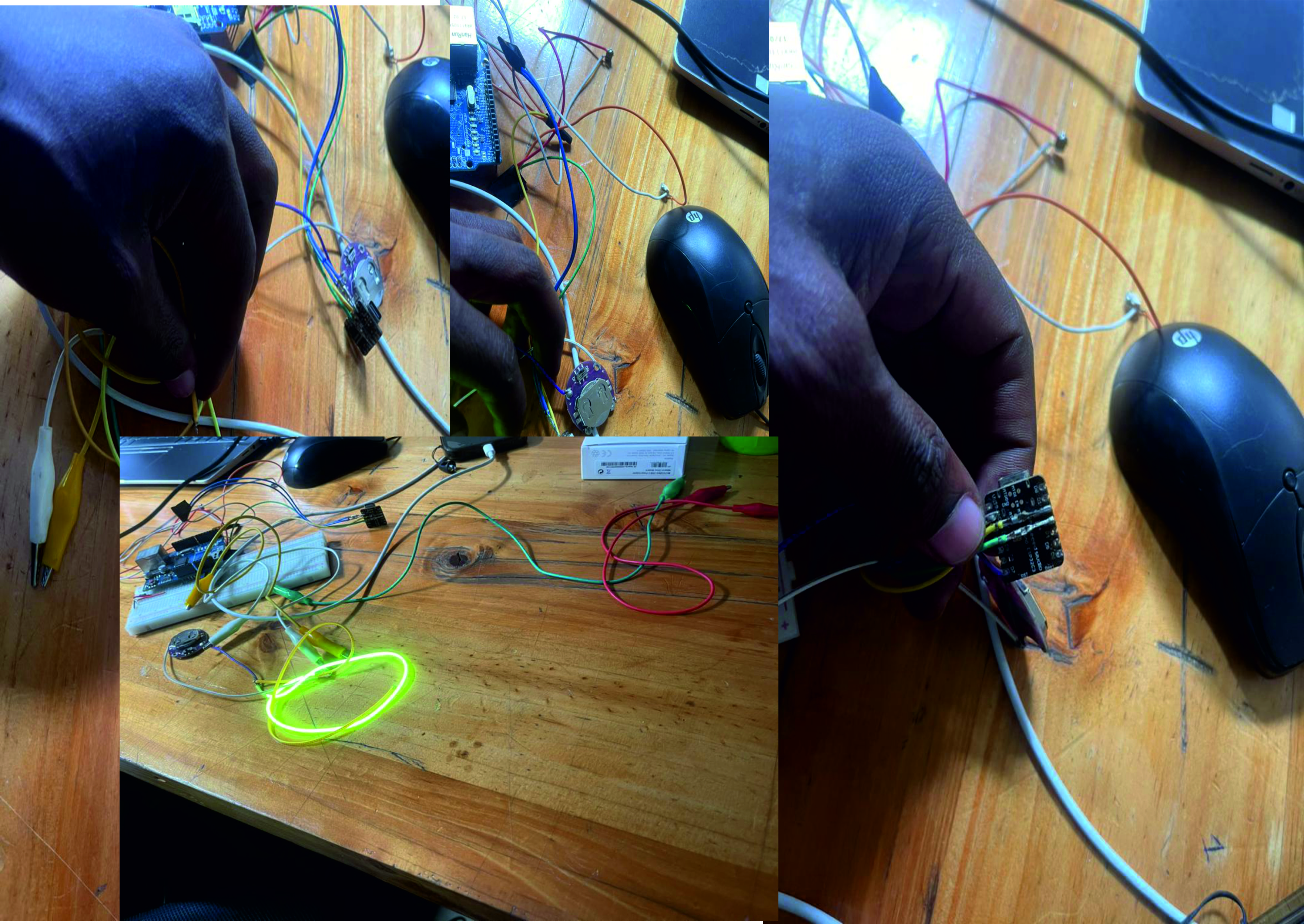
2️⃣Hardware Setup (Wiring Diagram)
A. MPU-6050 → Arduino
MPU-6050 Arduino
VCC → 5V GND → GND SCL → A5 SDA → A4
B. LED Connections
FS1 (+) → D2 through 220Ω resistor
FS2 (+) → D3 through 220Ω resistor
FS3 (+) → D4 through 220Ω resistor
All FS (-) → GND
Software Setup
FS MEANS flexible silicone
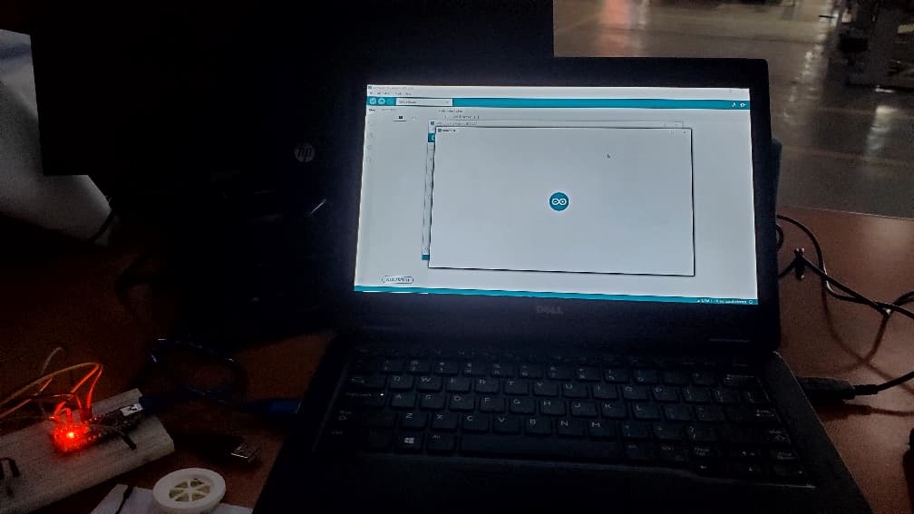
3️⃣Open Arduino IDE
I Install MPU-6050 library: Sketch → Include Library → Manage Libraries → Search “MPU6050” → Install
I Connect TO Arduino using USB
Select:
Board: Arduino Nano
Port: I USE COM3 AS MY POT
4️⃣ Code
MPU6050 mpu;
int ledX = 2; int ledY = 3; int ledZ = 4;
void setup() { Serial.begin(9600); Wire.begin(); mpu.initialize();
pinMode(ledX, OUTPUT); pinMode(ledY, OUTPUT); pinMode(ledZ, OUTPUT); }
void loop() { int16_t ax, ay, az, gx, gy, gz;
mpu.getMotion6(&ax, &ay, &az, &gx, &gy, &gz);
// LED1 - X axis tilt if (ax > 2000) digitalWrite(ledX, HIGH); else digitalWrite(ledX, LOW);
// LED2 - Y axis tilt if (ay > 2000) digitalWrite(ledY, HIGH); else digitalWrite(ledY, LOW);
// LED3 - detect shake if (abs(gx) > 15000 || abs(gy) > 15000 || abs(gz) > 15000) { digitalWrite(ledZ, HIGH); delay(200); } else digitalWrite(ledZ, LOW);
delay(50); }
5️⃣Uploading & Debugging
Steps:
Click ✔ Verify
Click ➡ Upload
Open Serial Monitor at 9600 baud
Move the MPU-6050 and watch the values change
Adjust threshold values if LEDs trigger too fast or slow
6️⃣Testing & Calibration
Test 1 – X-Axis Tilt (Left/Right)
Tilt sensor LEFT or RIGHT → FS1 (D2) turns ON
Test 2 – Y-Axis Tilt (Forward/Back)
Tilt sensor FORWARD or BACK → FS2 (D3) turns ON
Test 3 – Shake Detection
Shake sensor quickly
→ FS3 (D4) BLINKS
Results