9. Wearables
Research
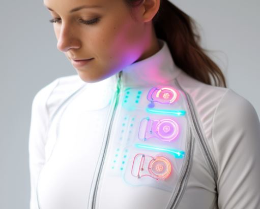
In this image, I see a wearable object designed to interact with the human body. The design combines textiles with electronic components, showing how technology can be integrated into clothing. The materials and shapes suggest flexibility, movement, and the idea of enhancing the body through soft circuitry or light. The image reflects the concept of wearables as both functional and expressive pieces.
"Lorem ipsum dolor sit amet, consectetur adipiscing elit, sed do eiusmod tempor incididunt ut labore et dolore magna aliqua. Ut enim ad minim veniam, quis nostrud exercitation ullamco laboris nisi ut aliquip ex ea commodo consequat. Duis aute irure dolor in reprehenderit in voluptate velit esse cillum dolore eu fugiat nulla pariatur. Excepteur sint occaecat cupidatat non proident, sunt in culpa qui officia deserunt mollit anim id est laborum."
- Two images side-by-side

🧰 Tools Needed
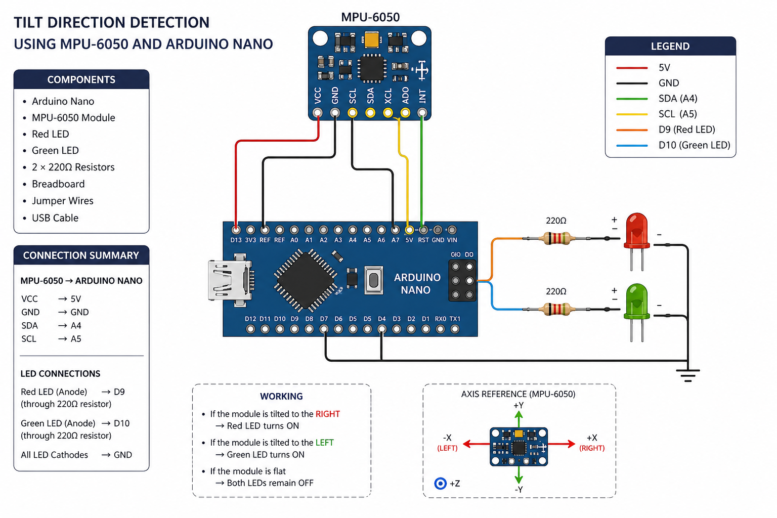
Arduino Nano MPU-6050 Red LED Green LED 2 × 220Ω Resistors Breadboard Jumper wires USB cable (for programming) Computer with Arduino IDE
⚙️ Process and Workflow 1. Understanding the Sensor
The MPU-6050 is an accelerometer + gyroscope module. It detects movement and orientation along X, Y, and Z axes.
👉 In this project:
X-axis tilt is used to detect left and right movement
- Circuit Setup Connections:
MPU-6050 → Arduino Nano
VCC → 5V GND → GND SDA → A4 SCL → A5
LEDs
Red LED → Pin D9 (through resistor) Green LED → Pin D10 (through resistor) All grounds connected together
Tools and Materials
1.Arduino Uno or Arduino Nano
2.MPU-6050 sensor module
3.red right
4.3 × 220Ω resistors
5.Breadboard
6.Jumper wires
7.USB cable
8.Software
9.Arduino IDE
“MPU6050” library (installed from Library Manager)
Hardware Setup (Wiring Diagram)¶¶
A. MPU-6050 → Arduino
MPU-6050 Arduino VCC → 5V GND → GND SCL → A5 SDA → A4
B. LED Connections
FS1 (+) → D2 through 220Ω resistor FS2 (+) → D3 through 220Ω resistor FS3 (+) → D4 through 220Ω resistor All FS (-) → GND Software Setup FS led
My sketches are

Code
```
// #include
include 
MPU6050 mpu;
int redLED = 9; int greenLED = 10;
void setup() { Wire.begin(); Serial.begin(9600); mpu.initialize();
pinMode(redLED, OUTPUT); pinMode(greenLED, OUTPUT);
if (!mpu.testConnection()) { Serial.println("MPU6050 connection failed"); } else { Serial.println("MPU6050 connected"); } }
void loop() { int16_t ax, ay, az; mpu.getAcceleration(&ax, &ay, &az);
Serial.print("X: "); Serial.println(ax);
if (ax > 5000) { // Tilt Right digitalWrite(redLED, HIGH); digitalWrite(greenLED, LOW); } else if (ax < -5000) { // Tilt Left digitalWrite(redLED, LOW); digitalWrite(greenLED, HIGH); } else { digitalWrite(redLED, LOW); digitalWrite(greenLED, LOW); }
delay(300); }() { // initialize digital pin LED_BUILTIN as an output. pinMode(LED_BUILTIN, OUTPUT); }
Results
Video
🧣 Smart Scarf Alert System
📌 Project Description
This project is a smart wearable scarf that can detect when it is removed from the body. The system uses a light sensor connected to an Arduino Nano and Lilypad components.
When the scarf is worn, the sensor is covered and detects low light. When the scarf is removed, the sensor is exposed to light, and a buzzer produces a sound to alert the user.
Through this project, I learned:
How to integrate electronics into textiles (wearable technology) How to use Arduino Nano with sensors and output devices How to connect and test Lilypad components How to solve problems during wearable system development
🧰 Materials and Tools
Arduino Nano Lilypad light sensor Lilypad buzzer Conductive thread / jumper wires Scarf fabric Needle and thread Battery pack Breadboard (for testing)
⚙️ Working Principle
The system works based on light detection:
When the scarf is worn → the sensor is covered → low light detected When the scarf is removed → the sensor is exposed → high light detected The Arduino reads this change and activates the buzzer
🔌 Circuit Connections
Sensor → Analog pin A0 Buzzer → Digital pin D9 VCC → 5V GND → GND
💻 Code Explanation
The Arduino reads the sensor value continuously. If the value is higher than a set threshold, it means the scarf is removed, and the buzzer is turned on. Otherwise, the buzzer stays off.
int sensorPin = A0; int buzzerPin = 9; int threshold = 500; // adjust based on testing
void setup() { pinMode(buzzerPin, OUTPUT); Serial.begin(9600); }
void loop() { int sensorValue = analogRead(sensorPin); Serial.println(sensorValue);
if(sensorValue > threshold) { digitalWrite(buzzerPin, HIGH); // scarf removed } else { digitalWrite(buzzerPin, LOW); // scarf worn }
delay(200); }
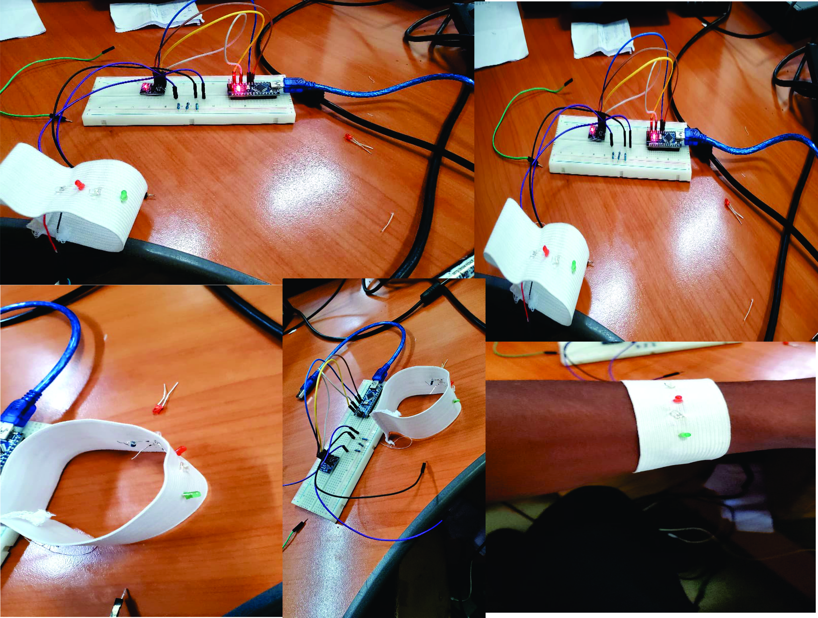
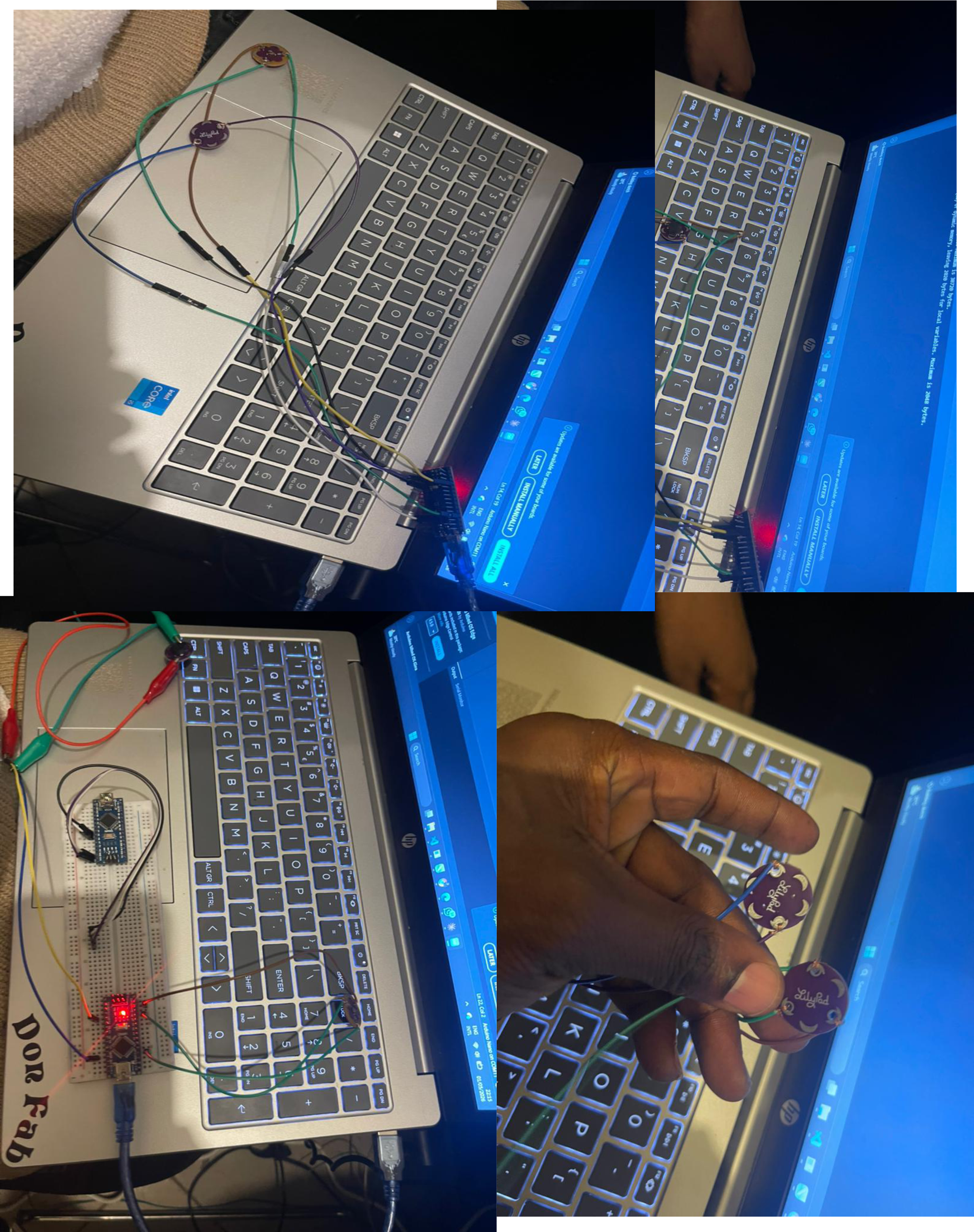
🧪 Testing Process
First, I tested the circuit using a breadboard before integrating it into the fabric.
When I covered the sensor → no sound When I exposed the sensor to light → buzzer produced sound
This confirmed that the system works correctly.
🧵 Textile Integration
After testing, I integrated the electronics into the scarf:
I sewed the Lilypad components onto the fabric I used conductive thread to connect the circuit I placed the sensor inside the scarf fold near the neck I hid the buzzer inside the scarf
## ✅ Results
The final scarf successfully detects when it is removed. The buzzer gives an immediate alert. The system is wearable and functional.
Future Improvements
Add LED for visual feedback Use a vibration motor instead of a buzzer Add Bluetooth for phone notifications Make electronics detachable for washing