12. Skin Electronics
Research
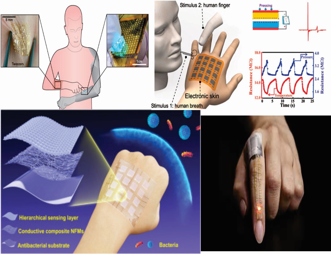
Skin electronics explore the integration of soft, flexible, and body-safe electronic components directly onto the skin or close to the body. These systems commonly use temporary tattoo circuits, conductive inks, silicone substrates, flexible PCBs, and wearable sensors. The goal is to create electronics that feel natural, stretch with the skin, and provide interaction without traditional rigid hardware.
They are used in applications such as:
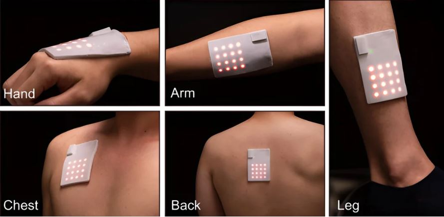
Health monitoring (heart rate, hydration, movement sensors)
Interactive performance (light-reactive tattoos, gesture control)
Fashion and body art
Soft robotics and prosthetics
Researchers in this field focus on material softness, biocompatibility, sensor accuracy, and user comfort. Different fabrication techniques include screen-printing conductive inks, laser cutting circuits, vinyl cutting, flexible microcontrollers, and temporary tattoo substrates.
Skin electronics push the boundaries of how technology blends into daily life, enhancing personal expression, healthcare, and interactivity.
References & Inspiration
Tools AND workflow
🧩 1. Materials & Components
- 🔌 Electronics
- Seeed Studio XIAO ESP32-C3
- × RGB LEDs (4-pin, common cathode)
- 9 × resistors (220Ω–330Ω)
- wires
- 🔋 Power Supply
- USB cable (5V)
- Cumputer
- RGB LED (4-pin)
NOTE: Each RGB LED contains:
Red channel Green channel Blue channel Common pin (long leg)
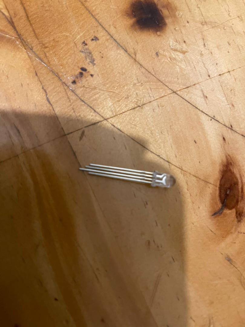
👉 The long leg = COMMON (connected to GND for this project)
Resistors
Each color channel requires a resistor:
Prevents LED damage Controls current flow
Total resistors:
3 LEDs × 3 colors = 9 resistors Microcontroller
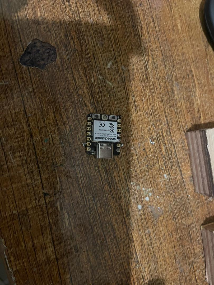
The Seeed Studio XIAO ESP32-C3 controls the LED using PWM (Pulse Width Modulation), allowing smooth color mixing.
2. System Architecture
Input
No input (autonomous system) (Expandable with sensors)
utput
RGB LEDs (light-based feedback) Processing Microcontroller generates PWM signals
3 Circuit Design
| Function | XIAO Pin |
|---|---|
| Red | GPIO3 |
| Green | GPIO4 |
| Blue | GPIO5 |
| GND | GND |
All LEDs share the same control pins:
All Red pins → GPIO3 (via resistors)
All Green pins → GPIO4 (via resistors)
All Blue pins → GPIO5 (via resistors)
All Common pins (long legs) → GND
Full Circuit Diagram
            GPIO3
              │
    ┌─────────┼─────────┐
    │         │         │
 [220Ω]    [220Ω]    [220Ω]
    │         │         │
  LED1 R    LED2 R    LED3 R

            GPIO4
              │
    ┌─────────┼─────────┐
    │         │         │
 [220Ω]    [220Ω]    [220Ω]
    │         │         │
  LED1 G    LED2 G    LED3 G

            GPIO5
              │
    ┌─────────┼─────────┐
    │         │         │
 [220Ω]    [220Ω]    [220Ω]
    │         │         │
  LED1 B    LED2 B    LED3 B
All LED COMMON (long legs) ─────────── GND
💻 7. Programming Software Arduino IDE ESP32 board package installed
 Code Explanation
PWM channels control brightness
Colors are mixed using RGB values
Loop cycles through color patterns
Code Explanation
PWM channels control brightness
Colors are mixed using RGB values
Loop cycles through color patterns
int redPin = 3;
int greenPin = 4;
int bluePin = 5;
void setup() {
ledcAttachPin(redPin, 0);
ledcAttachPin(greenPin, 1);
ledcAttachPin(bluePin, 2);
ledcSetup(0, 5000, 8);
ledcSetup(1, 5000, 8);
ledcSetup(2, 5000, 8);
}
void setColor(int r, int g, int b) {
ledcWrite(0, r);
ledcWrite(1, g);
ledcWrite(2, b);
}
void loop() {
// Primary colors
setColor(255, 0, 0); delay(500);
setColor(0, 255, 0); delay(500);
setColor(0, 0, 255); delay(500);
// Secondary colors
setColor(255, 255, 0); delay(500);
setColor(255, 0, 255); delay(500);
setColor(0, 255, 255); delay(500);
// White
setColor(255, 255, 255); delay(500);
}
<## Results
All 3 RGB LEDs function correctly
Smooth color transitions achieved
System stable under continuous operation>