Digital Bodies

1. Objective
Design and develop an original piece through 3d scanning, modelling and mesh repair, starting from the ideation to production with laser cutting, resulting in an assembled piece and it's documentation so others can replicate it.
2. References, research & inspiration
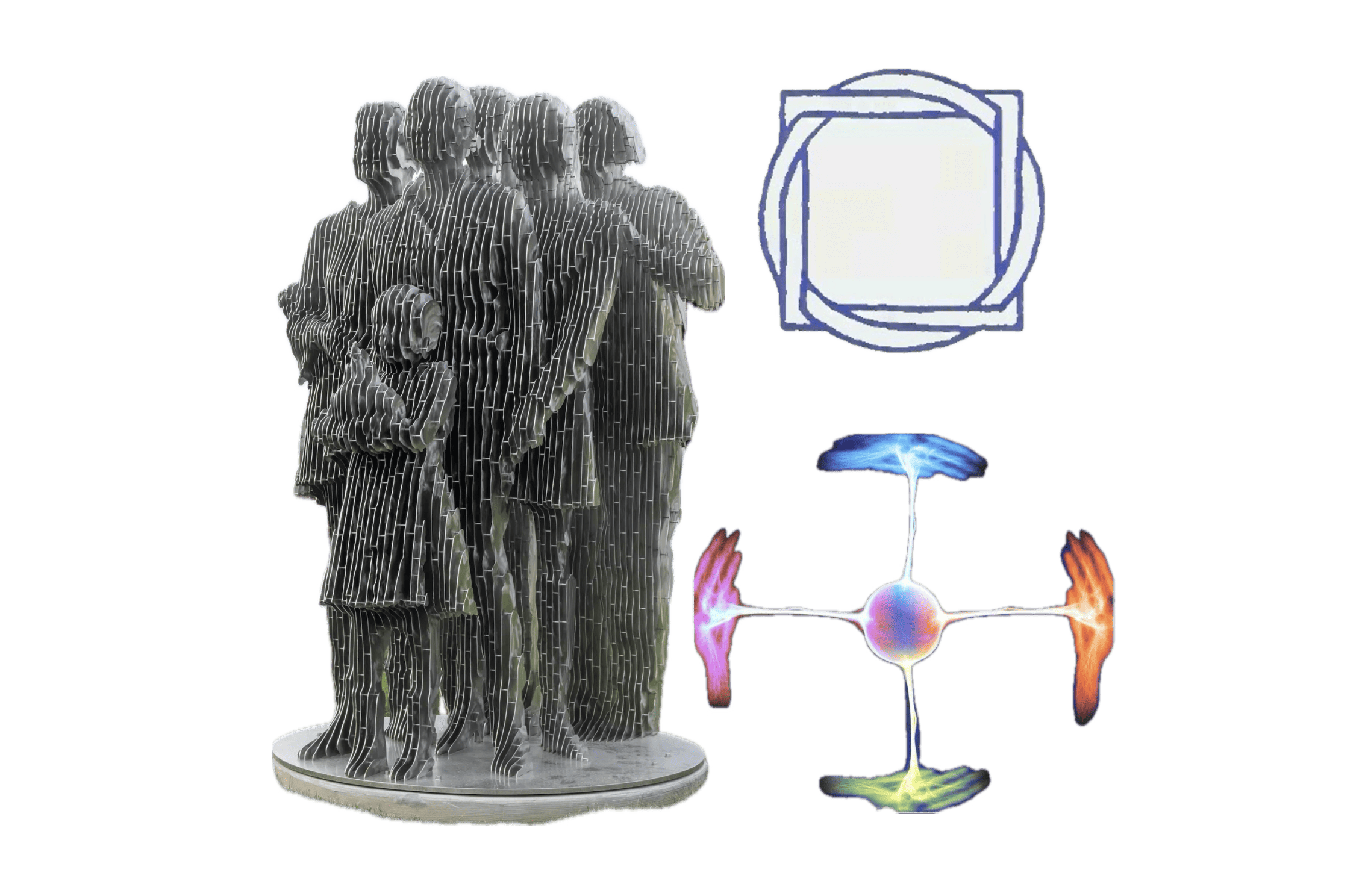
For this assignment I took some inspiration from Julian Voss-Andreae sculptures. I liked how these can give certain optical illusion, when seen from certain angles, they seem to disappear.
I also took one of my beliefs as what I wanted to transmit with this piece: Interconnectivity
I think there's an interconection between every being in this dimension and others. I perceive humans as a whole consciousness divided in different bodies, as a team of reflections.
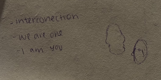
For the creation of it I first did a small draft with the idea and what I wanted it to mean.
3. Tools
- MakeHuman - To make different faces
- Creality scanner - Exploration scanning
- Blender - Mesh repair
- SmartCarve - For laser cut
- Slicer for fusion360 - For slicing my 3d model
- Polycam - To scan
4. Process and workflow
4.1 Creation
I started doing some different looking people in makehuman software, I intended to make them as different as possible between each other.
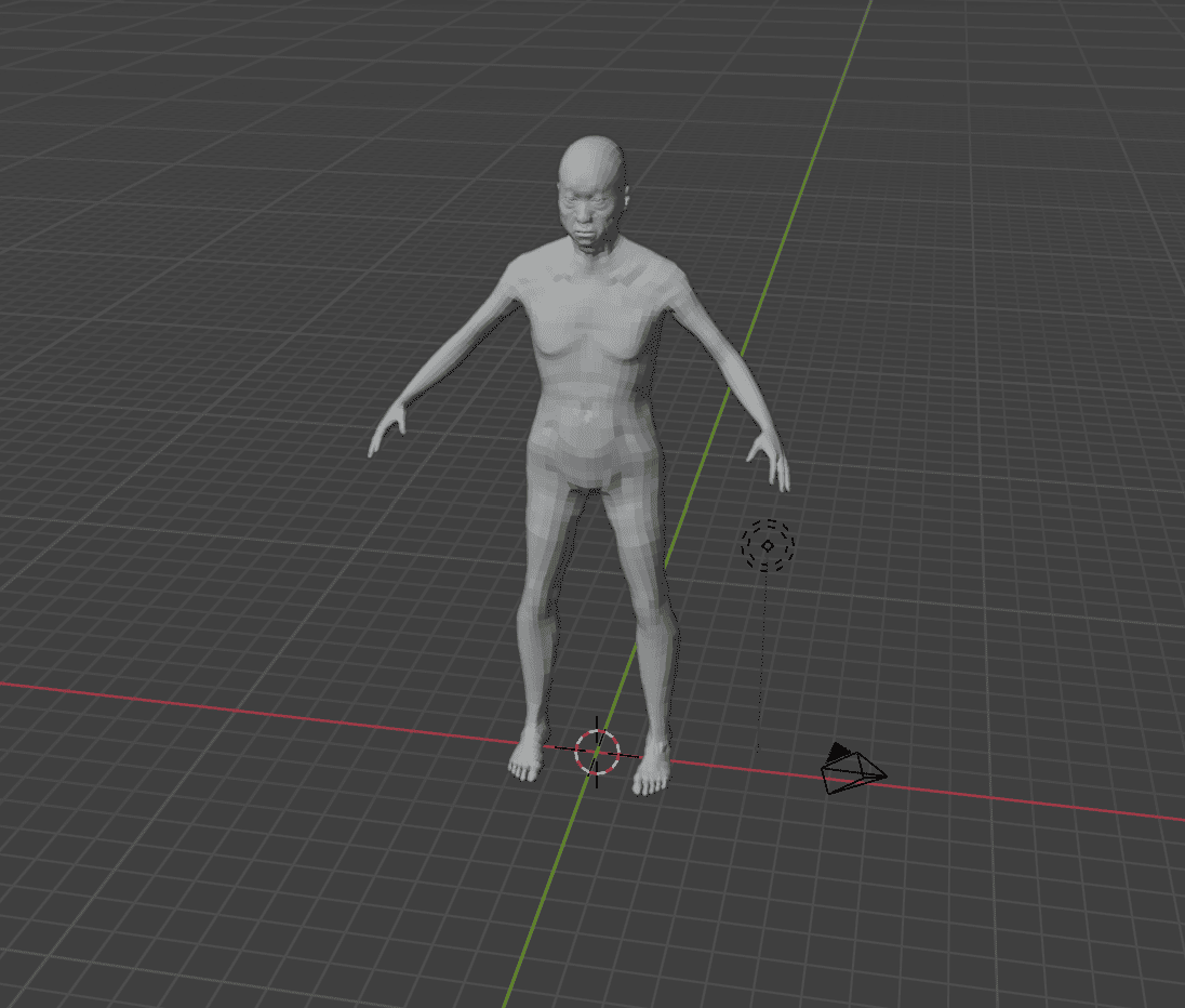
Then I saved them as .obj and translated them to blender, where I separated them and kept their heads.
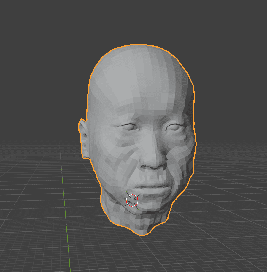
4.2 Adding me
I also scanned my face using polycam on my phone
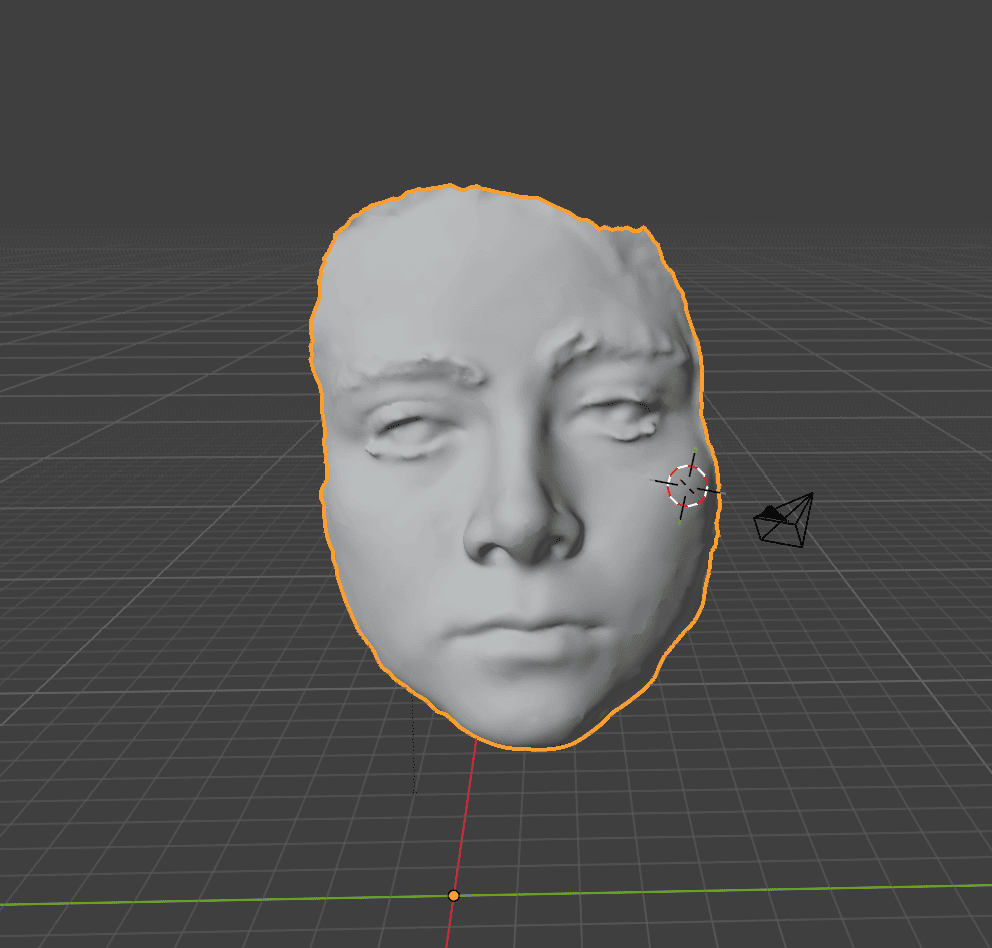
4.3 Merging
Then I imported all the faces a new file in blender, where I arranged them as I liked.
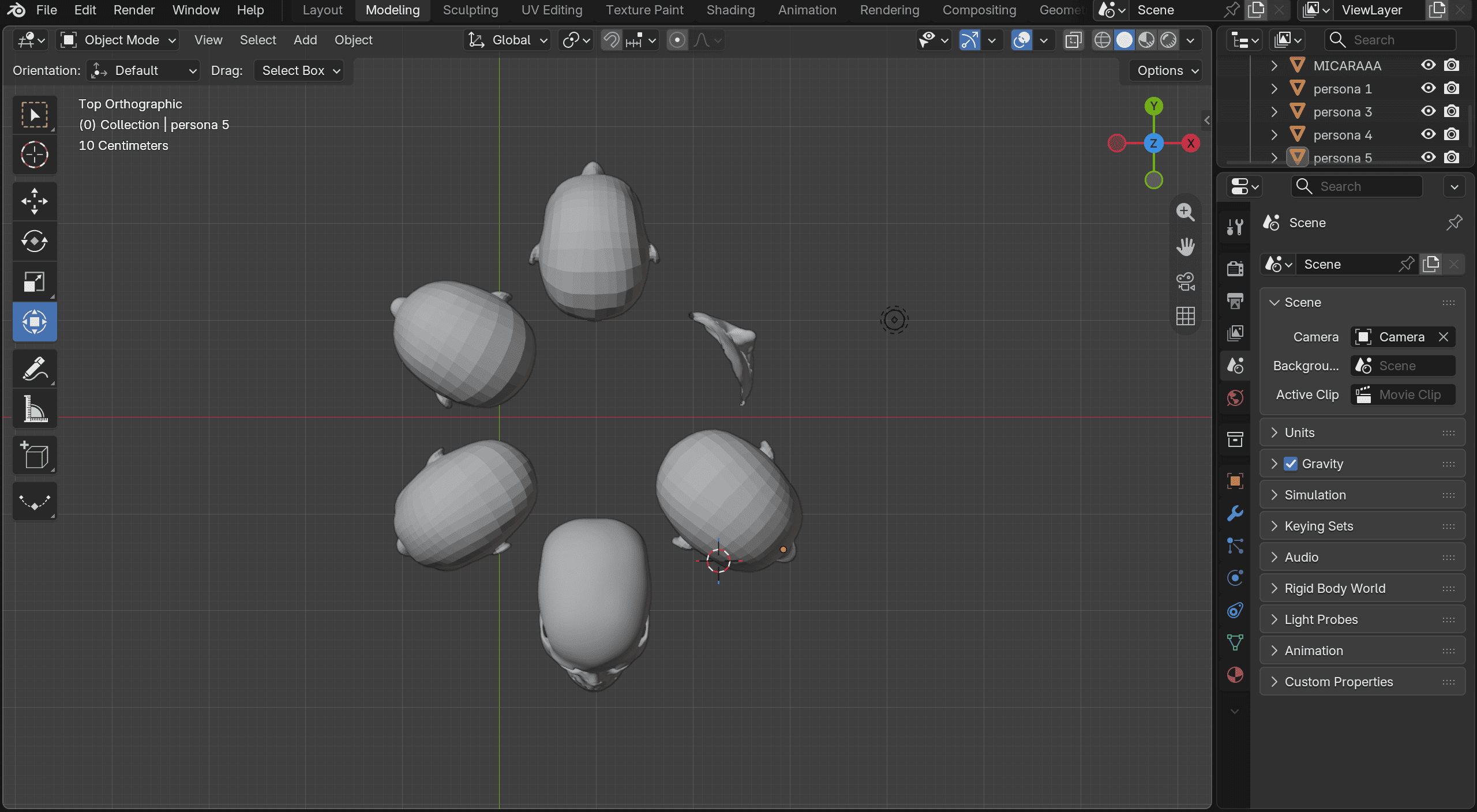
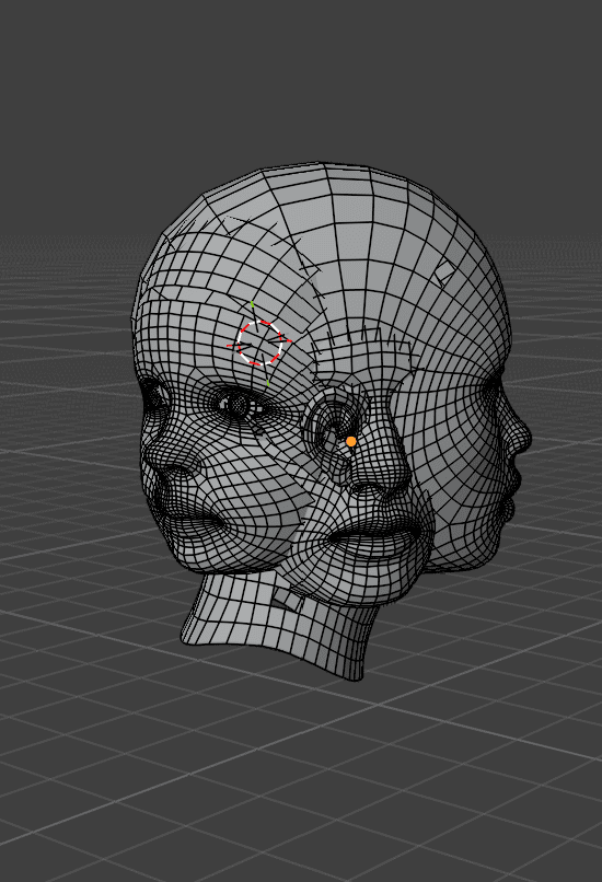
To join them and making sure it was watertight and ready to be sliced I selected all of them and used:
Ctrl+J -> remesh voxel mode -> apply
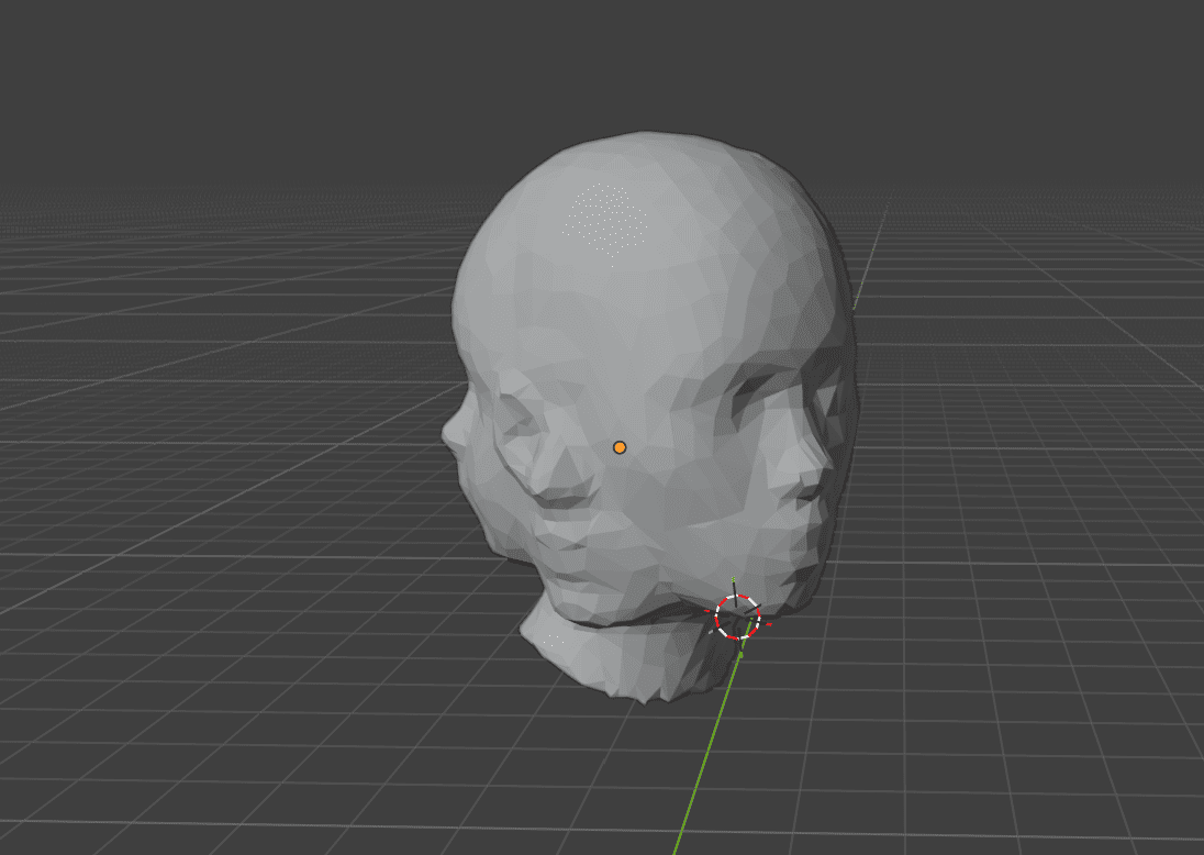
4.4 Slicing
For slicing it I used Slicer for fusion360
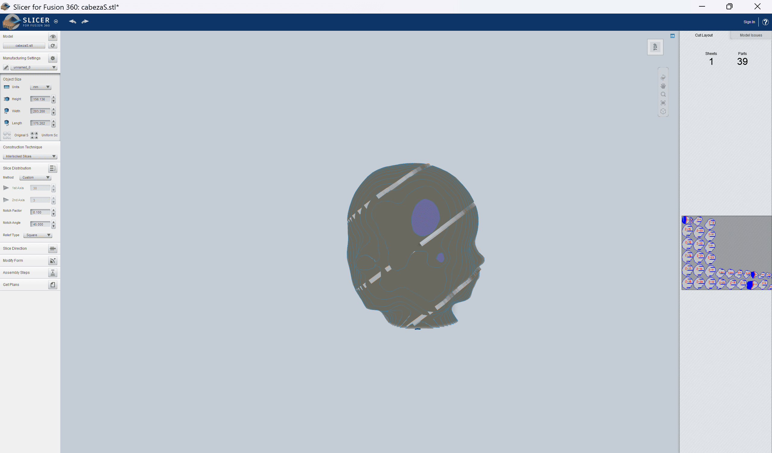
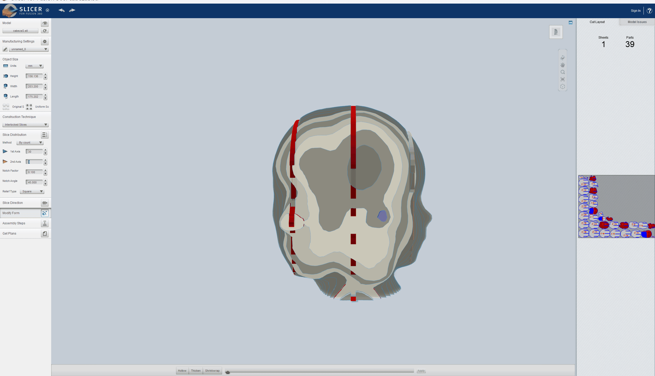
I explored different variations where I struggled, because in most of them, the faces siluettes weren't really noticeable which affected the optical ilusion I was trying to make. When I found one that fullfilled what I was looking for, I exported the file.
4.5 Laser cut machine
For a succesfull use of the laser cut machine, I made this easy guide.
4.6 Laser tests
Before cutting the slices I did 2 material tests.
Parametrization The first thing I did was a file using rhino, it consisted of a chart of power and speed, started with power in 15 till 95, increasing by 10. And a speed of 80 to 200, increasing by 10 and after 5 values, by 20.
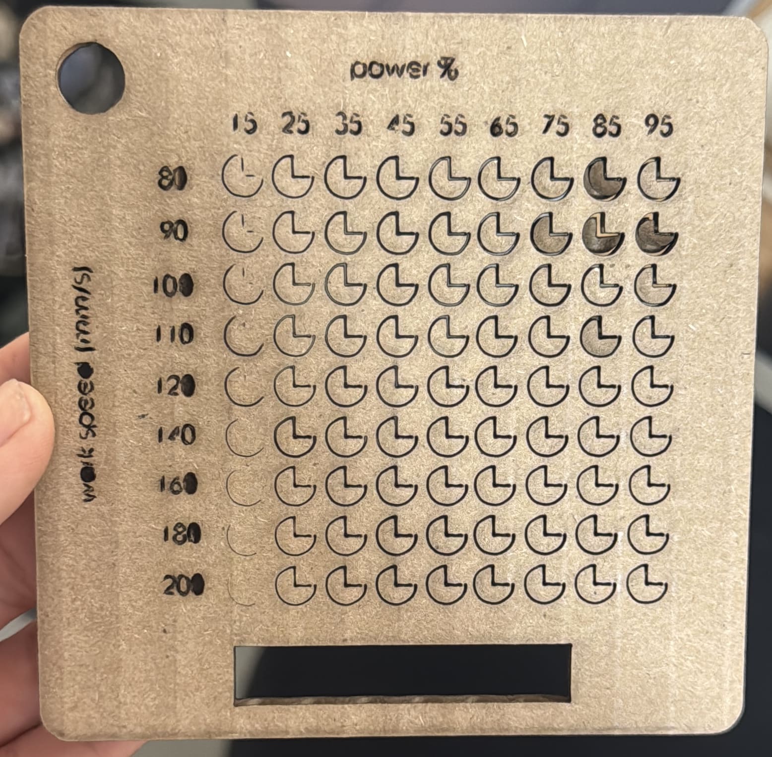
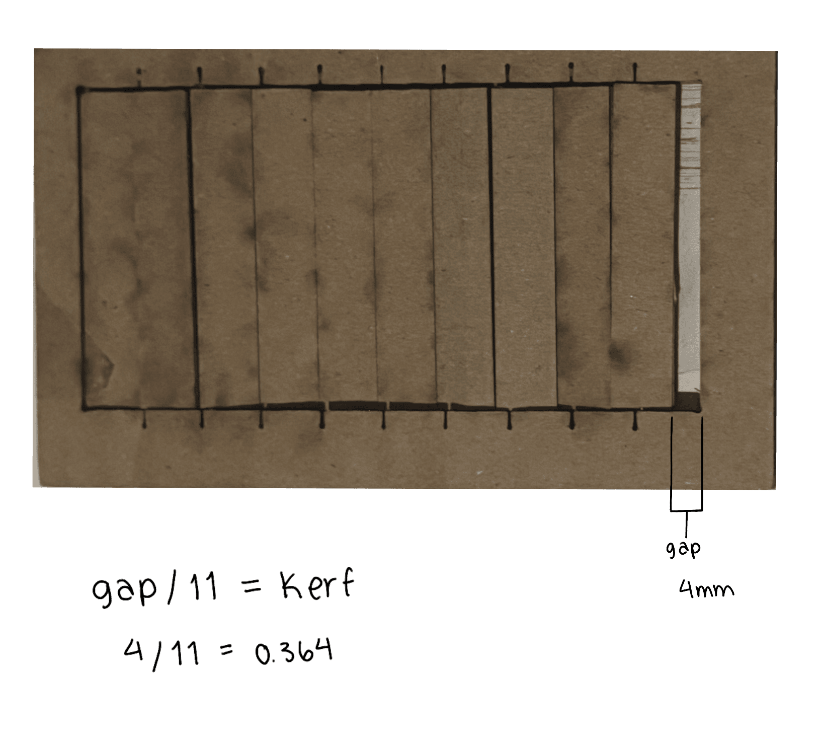
Kerf For this test I did a dxf file with a rectangle with 11 lines. Using the parametrization reference I used a maximum power of 95 and a minimum power of 85, speed of 80 to cut the material. After cutting, I dragged all the rectangles to one side and with a vernier caliper measured the gap, which gave me 4 mm. Using the kerf formula Gap/lines=kerf 4/11=0.364 mm
4.7 Cutting
After doing the tests I cut the slices for my piece.
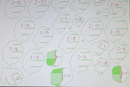
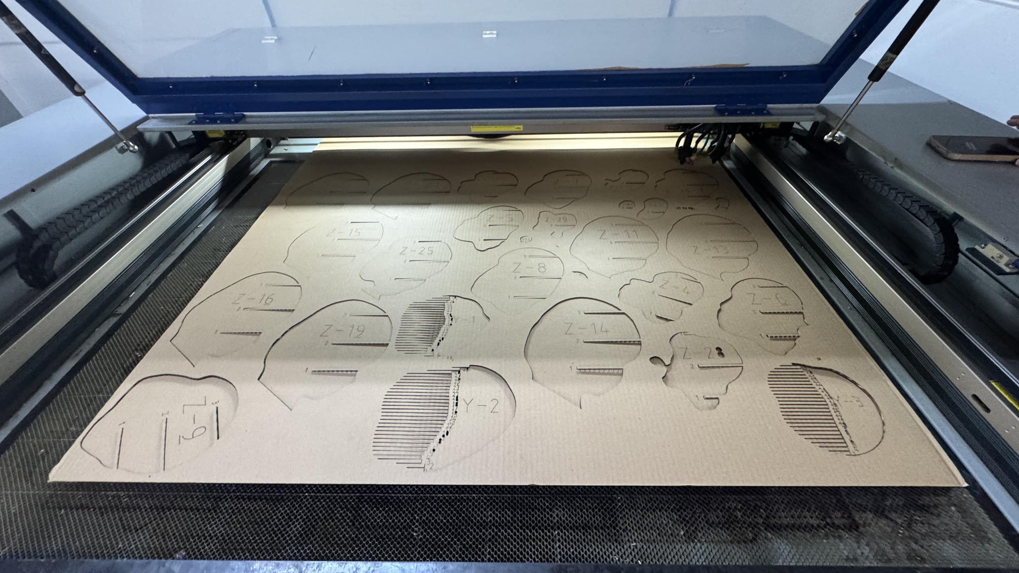
The parameters I chose, due to the parametrization test were:
For engraving: Power: max. 25, min. 15. Speed: 150%
For cutting: Power: max. 95, min. 85. Speed: 80%
5. Results
After assembling it, this is the result:
6. Weekly reflection & critical thinking
Before this assignment I've never used a scaner, it was really interesting to see how many possibilities this can open, I also enjoyed figuring out a way of keeping the essence of my piece while slicing it. I made some mistakes on this piece, some parts of the assembly broke, but I think I found a way of making it work, now I know how to evaluate better if this is happening. I also learned how to use the laser cut machine on my own, which I believe is useful for my trajectory as a designer and also opens a possibility for my final project.
Now I would like to experiment cutting with a biomaterial, given that most of the environmental impact of this machine is generated because of the material it is used with.