10. E-Textiles and Wearables II
I really fall in love with the flip dot sample ! I see a direct application in my final project so I really wanted to make a sample that's works. I really love this wearable subject, and i want to dive in deeply, but I also need to take time to well understand, not to skip the translation, I've made stupids mistakes which make me lost lot of time because of this.
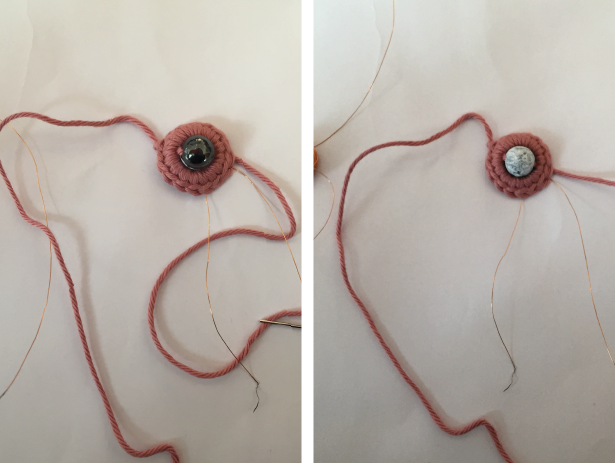
Flip dot and crochet
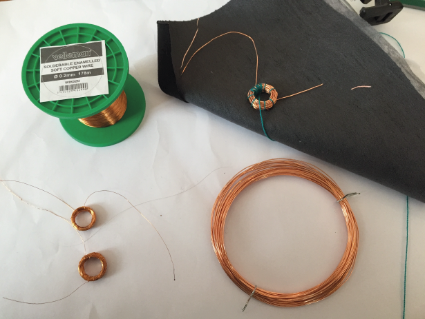
I first try with the copper wire on the right, I manage to make about 20-30 rounds, so it wasn't working at all, it just make a small movement with the smaller beads. So I run to buy a thinner copper wire, and found the one on the left witch is 0,2mm diameter. I did more than 100 rounds and crocheted it.
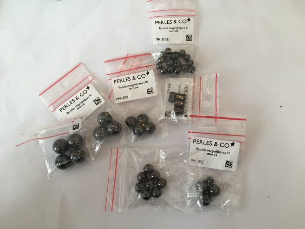
Here are all the differents beads I bought form 6mm to 12mm


Next step, keep going to imaging how to integrate this flip dot in my breast and bra theme for my final project. What sensor will do the connection ?
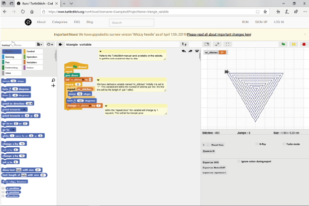
Speakers
I want to try to make a speaker bra with this Turtle Stitch embroidery I already test in a previous class. But when I made it with the embrodeiry machine and Madeira Resistive Thread, I notice that the lines touch each other in the edges.
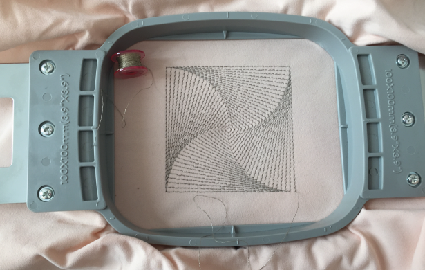
So I start an other design, but I did not ge time to embroidery yet
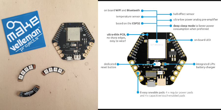
ESP32 wearable Development Board (compatible Arduino) & BrigthDots
Discovery
For the prototyping part, I choose to knot conductive thread, and I isolated with tape to avoid short circuit
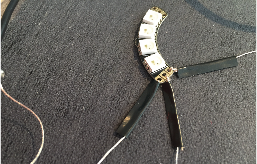
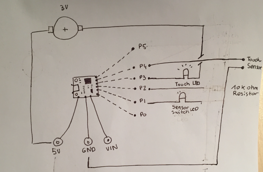
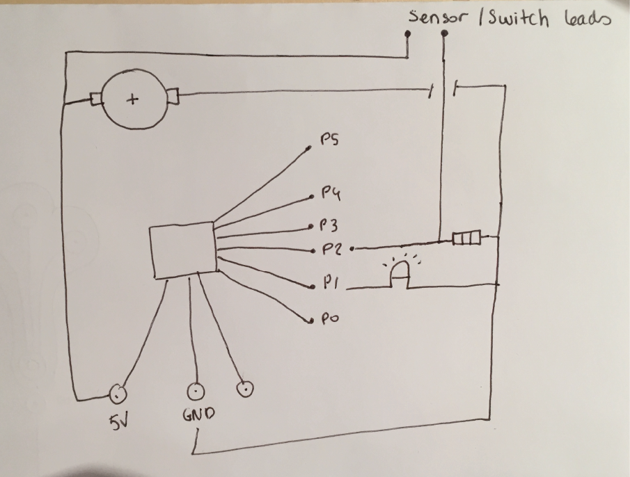
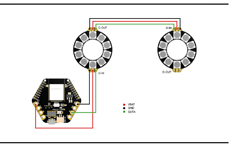
I adapt this draw for the electronic circuit. The first thing to keep in mind is that 3 things will need to flow from the development board to the BrightDot module :
- data (D-OUT to D-IN to D-OUT and so on): data is a signal that is generated from the code which is programmed onto your development board. The data signal 'flows' from your development board's digital output pin to the BrightDot's digital input pin, addresses each LED and continues to flow to the next output pin. You will learn more about programming in the next chapter! But first, you will need to make a proper connection scheme.
- ground (GND to GND): negative power signal
- power (3V3 to VDD): positive power signal
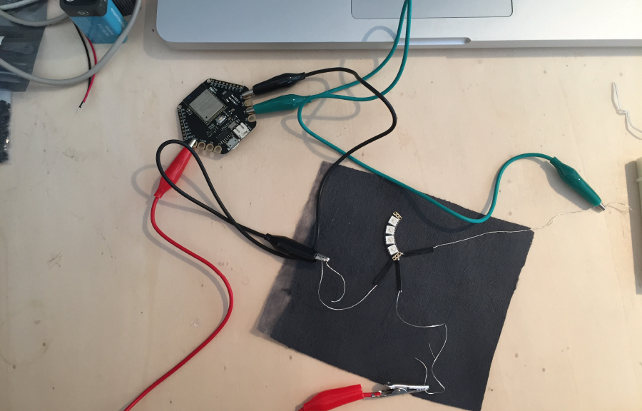
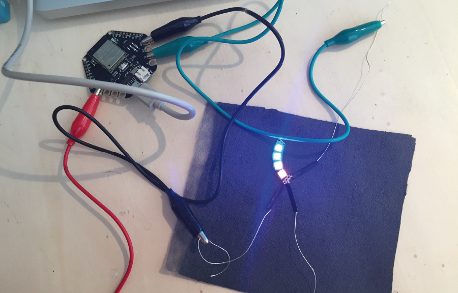
In order to start off quick, I simply used the pre-programmed a rainbow sequence for maximum 10 LEDs on pin T5. This code will also work for less than 10 LEDs. I plug the board with usb to my computer.
https://github.com/Velleman/BrightDotExampleCodes/blob/master/BrightDotMainExample/BrightDotMainExample.ino
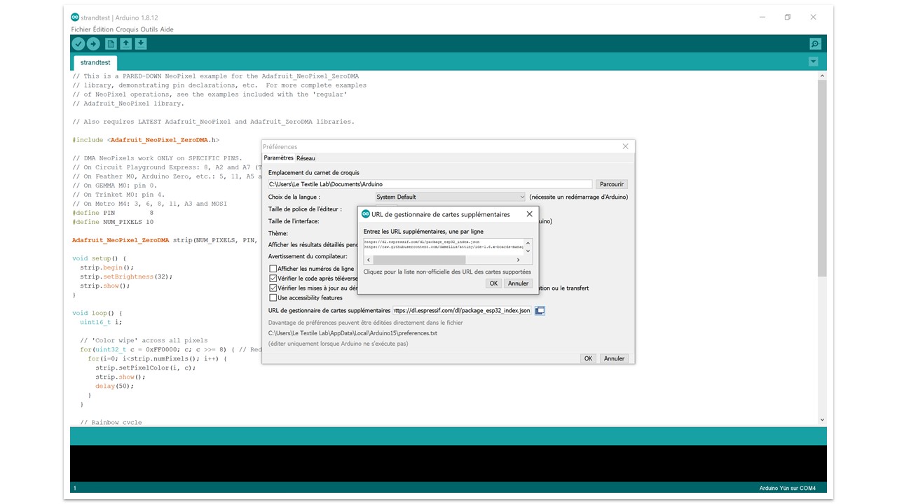
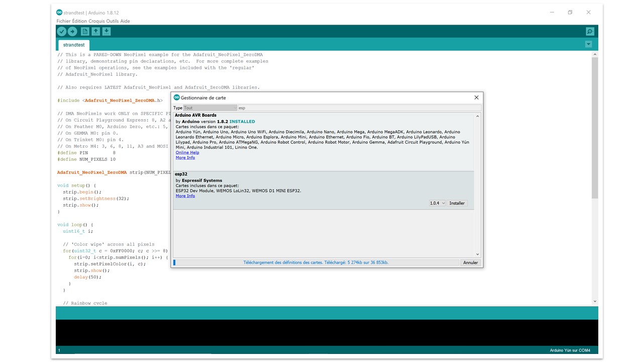
Programing the board with arduino
docs/files/ch340g_driver.zip
docs/files/brightdot_example_code.ino
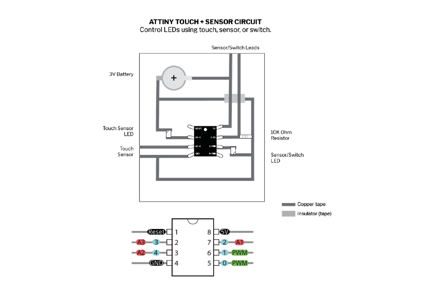
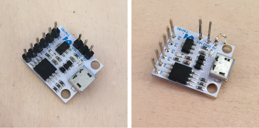
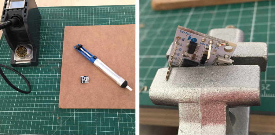
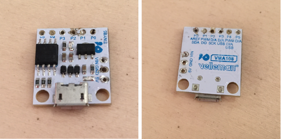
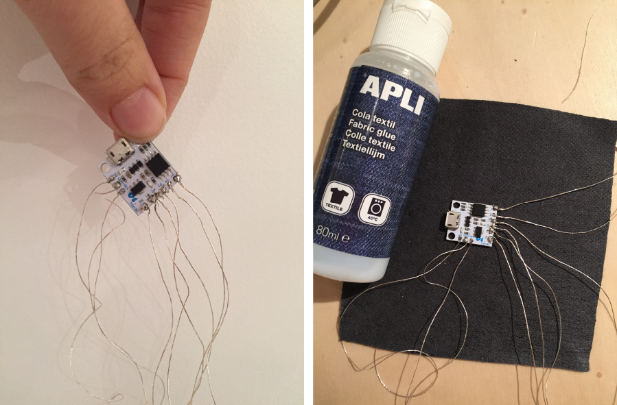
ATtiny
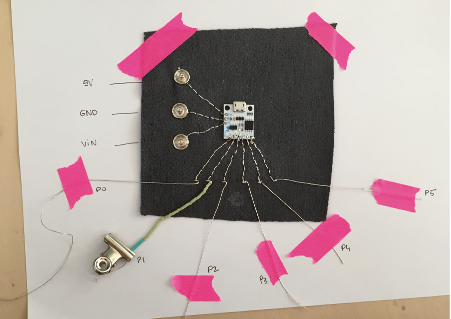
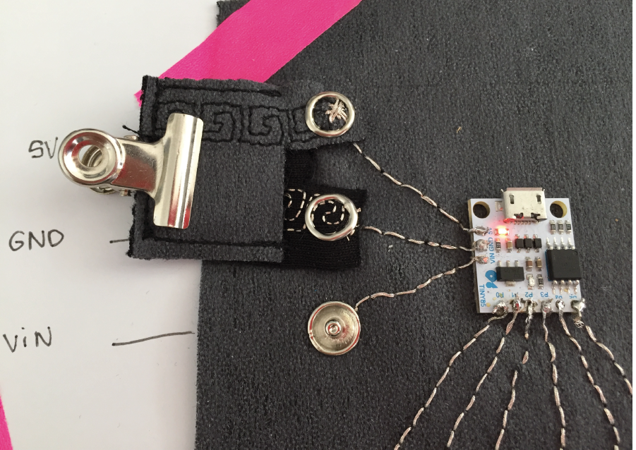
Making a soft developpement board with snap button
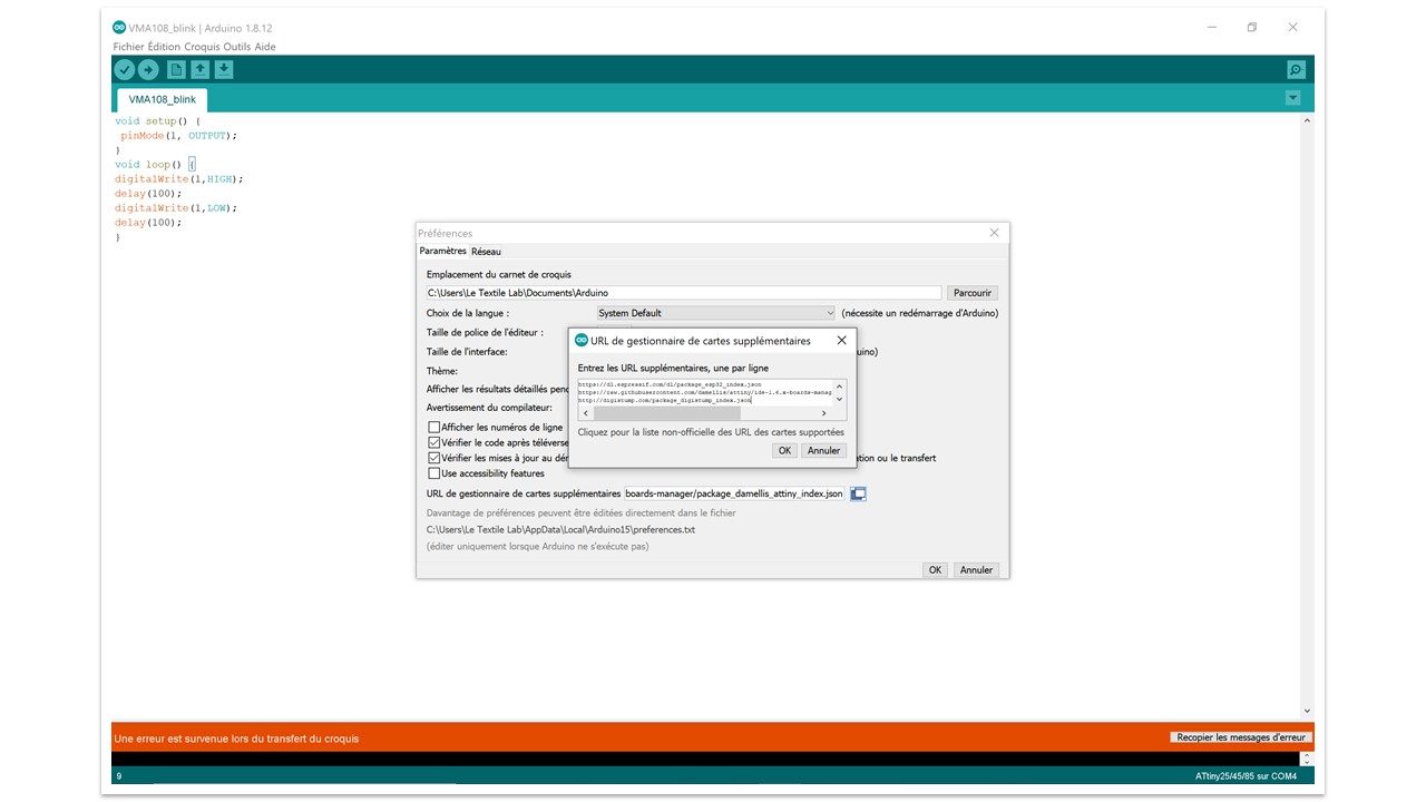
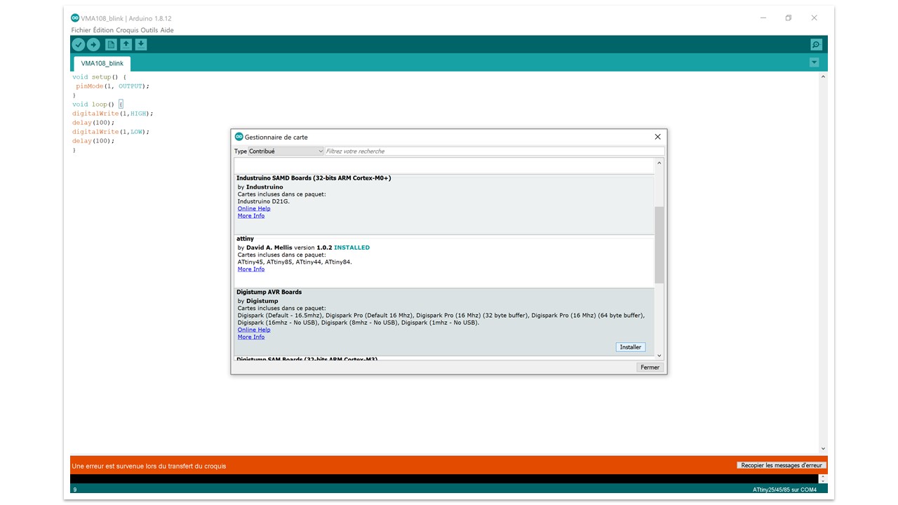
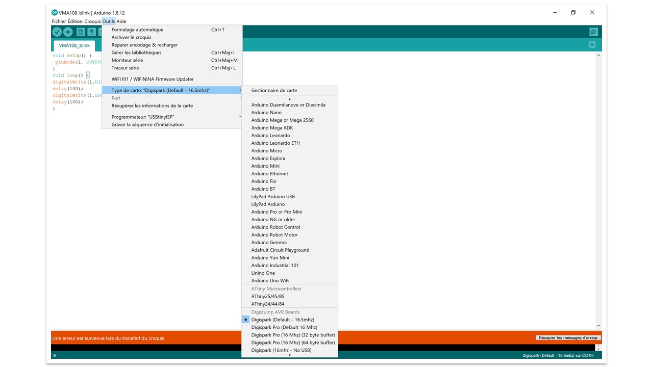
Programing the board with arduino