5. E-textiles

During the e-textile week, I learned how to create different electricity circuits, to use its functions, materials, tools, I saw again electricity language and its measures (again, because it reminded me old school memories), and many possibilities to do soft circuit with conductive yarns and fibers. Also, I discovered different possibilities of sensors switches (digital and analog).
Thuesday, Lisa Stark introduced this theme and presented circuits, materials, tools, connections, sensors and programming.
Then, Wednesday and Thursday, Emma Pareschi, animated three tutorials : basic electronics, introduction to sensors and introduction to Arduino. This week, I followed and experimented the different circuits show in tutorials in direct live with the tutorials.
All useful links to the bottom of the page.
Friday, with a little group I learned to use the embroidery machine and its software at Le TextileLab, with Diane. We experimented a flexible circuit with this machine.
Vocabulary, materials and tools
- Circuit : a circuit is a path for electricity to flow. The electricity travel in the counterclockwise way. (from power to ground + > -)
- Current (Amps - I) : rate at which at electrical charge flows
- Voltage (Vols - V) : electrical pressure of force between two points
- Resistance (Ohms – R) : The amount of material that resists the flow of current.
- Multimeter : a tool to measure voltage, ampere, current,…
Materials and tools
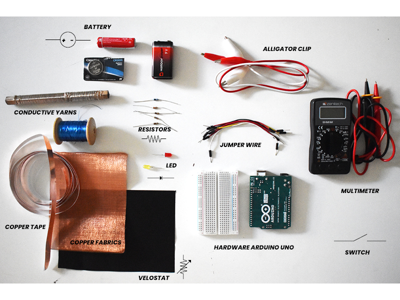
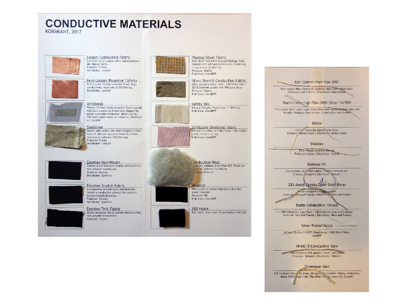
There are many other tools and conductive materials. See the Lisa Stark presentation (useful links)
TIPS : to know if a material is conductive use the multimeter on (add a picto) function.
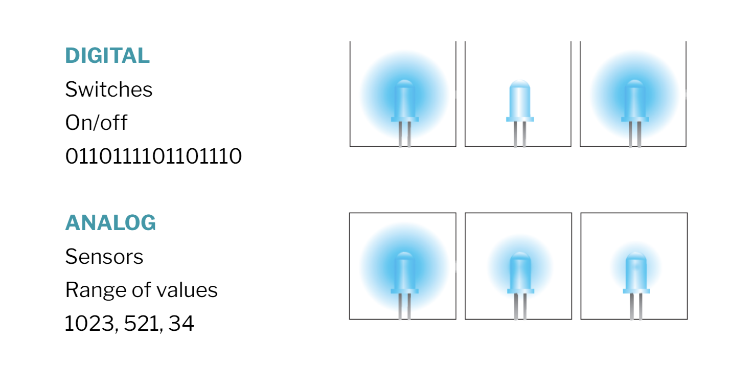
- Input : Information or data that enters a system, like a button press. (digital switches or analog sensors)
- Switches : a switch is a break in a circuit
Switch examples
Momentary : Momentary switches (aka push buttons) stay open as long as you hold them by pressing conductive materials into contact.
Toggle : Press, zip, slide, etc two pieces of conductive material together. These stay open in one position and closed in the other.
Tilt : A conductive bead or pompom makes contact with conductive fabric patches based on its position.
Stroke : Close the circuit by pressing conductive materials into contact.
- Sensors : We can use resistance to get a broader range of values. By allowing more current to get through, you can change the >brightness of an LED, the frequency of a sound, or the speed of a motor. By varying resistance of your input, you can change the output. That is why they are also called variable resistors.
Sensors
We can change resistance in three ways :
- Distance : Resistance increases over distance no matter what the material
- Contact : Some materials are pressure sensitive will decrease in resistance when pressure is applied to them.
- Surface area : Increasing the size of the area for electricity to flow will decrease the resistance.
| Material examples | Primary Uses | Properties | Resistance | Material |
|---|---|---|---|---|
| Conductive yarn | Stretch, pressure, and bend sensor | Resistance decreases across distance and changes under pressure. | <500 Ohms/cm | Silver spun with fiber; spun stainless steel wool fibers |
| Velostat | Pressure and bend sensor | Resistance decreases across distance and changes under pressure. | <500 Ohms/cm | Carbon impregnated black polyethylene film. Conductivity is not affected by humidity or aging. |
| Eeeontex | Pressure, potentiometer, stretch (if substrate is stretchy), and bend sensor | Re-sistance decreases across distance and changes under pressure. | Between 10 Ohm/sq and 10 billion Ohm/sq based on substrate and coating specs. | Proprietary coating system devel-oped by Eeonyx to coat any fabric with a conductive polymer. |
| Polysense | Pressure, potentiometer, stretch (if substrate is stretchy), and bend sensor | Re-sistance decreases across distance and changes under pressure. | Varies depending on process and substrate. 10K to 1M Ohm. | Uses a process called in-situ polymerization, effec-tively dying a fabric to become piezoelectric. Any porous material can be dyed/coated. Pro-cess was designed to be easily replicated. |
Sensor examples
Pressure sensors : When pressed, the resistance decreases allowing more electricity to flow through the circuit. Use this to track pressure/weight on an interface or object.
Bend sensors : Resistance decreases as bent and more contact is made. Very similar to a pressure sensor, but better for measuring joint movement.
Potentiometer sensors : Adjust resistance by connecting conductive and resistive ma-terial through a wiper at different points in the circuit. The farther away, the more re-sistance.
Stretch sensors : The more a resistive material is stretched, the more its resistance will decrease because it has more surface area to cover.
Accelerometer sensors : The weight at the end pulls and stretches the crochet or knit-ted structure as it gets accelerated. It works the best when this sensor (more of an ob-ject) is swung around like hammer throwing.
- Program : Arduino > An open-source electronics prototyping platform. It is a hardware and software.
- Pin : A pin is how inputs (buttons, etc) and outputs (LEDs, speakers, etc) communicate with the Arduino.
Work of the week
Circuit and sensors electronics
Circuit A circuit is a CLOSE LOOP in which electrons can travel in.
To create a circuit I need :
- Battery
- Material to let the electrons flow
- A load
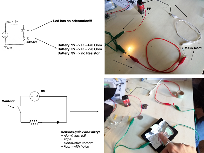
Functions of resistor in a circuit :
A resistor is one of the most fundamental components in electronics. Its purpose is to impede a flow of current and impose a voltage reduction.
It has two sides, it doesn’t matter the orientation.
Ohm’s Law defines the relation between voltage, current and resistor: V = I * R = IR
To know the R resitence in function of LED :
R = (Vs - Vled) / Iled
Sensors
We use sensors because the interaction of them generate an electric signal (a change of Voltage).
To use the switch as sensor you have to use an extra resistor. The name of the resistor is Pull-up resistor.
If the switch is open =>
- Vsense is High (VCC, 5V)
If the switch is close =>
- Vsense is LOW (GND, 0V)
Analog sensors
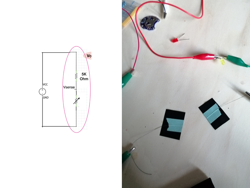
To use an analog sensor as sensor you have to use an extra resistor and place them in series, one after the other one.
This circuit, two resistors in series, is also known as Voltage divider.
In the Voltage Divider, the Voltage in between the resistors depends on the value of the resistor.
Calculate the output voltage :
V out = (Vs x R2) / (R1 + R2)
Voltage Divider Calculator
Program on Arduino
Arduino develop the physical computing, is an hardware (multiple for different using), a software and a community. Is about prototyping with electronics, turning sensors, actuators and microcontrollers into materials
Thursday, I experimented all Arduino sketches showed by Emma. (blink led, fade led, read digital sensors,button led, read analog sensors, pressure led.)
Language on Arduino :
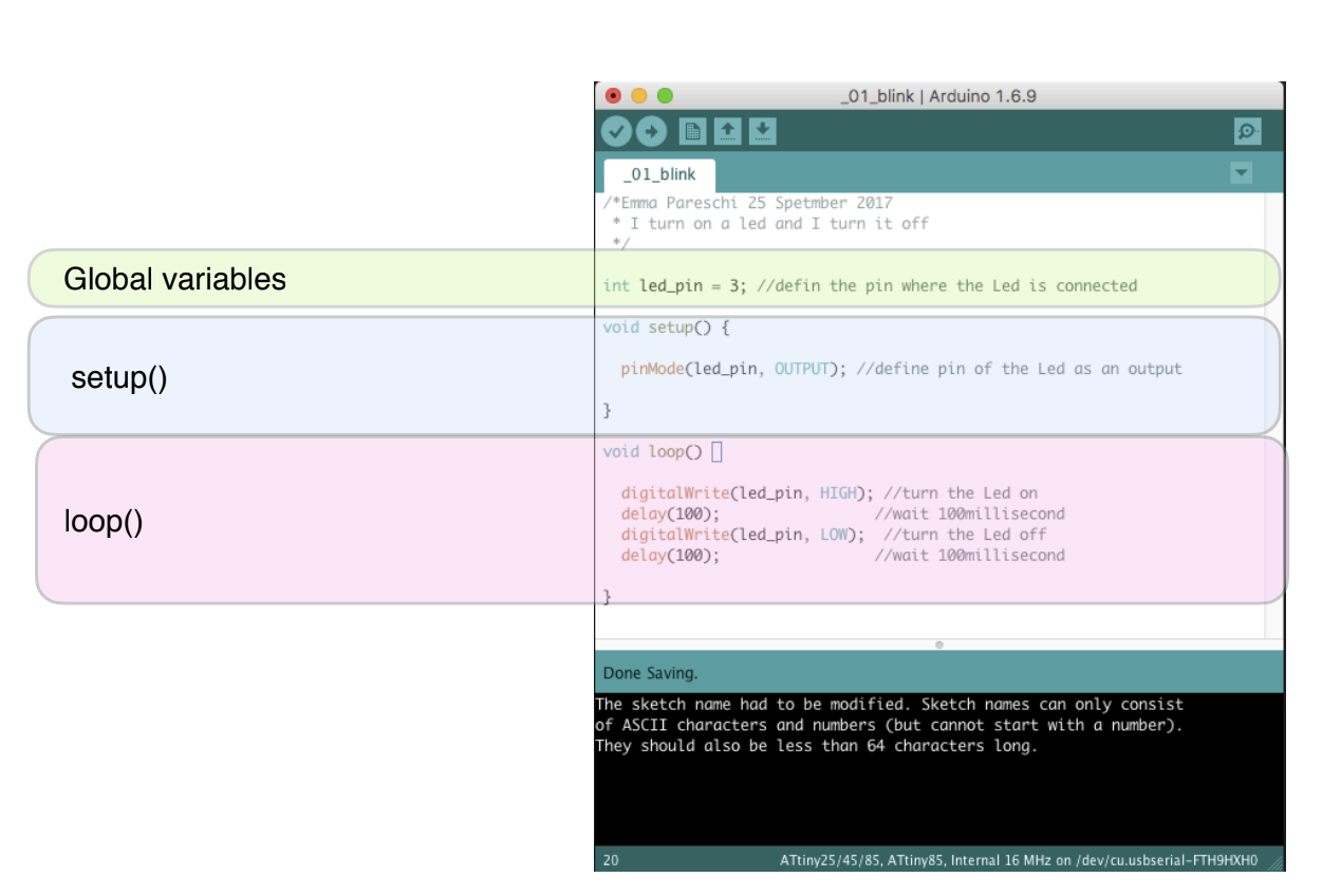
On arduino software there are different blocks :
Void setup : Function
Void loop : Command
When I add all informations, i must to close to finish the work :
{ : open
} : close
Some tests on Arduino
Blink LED
Pressure LED
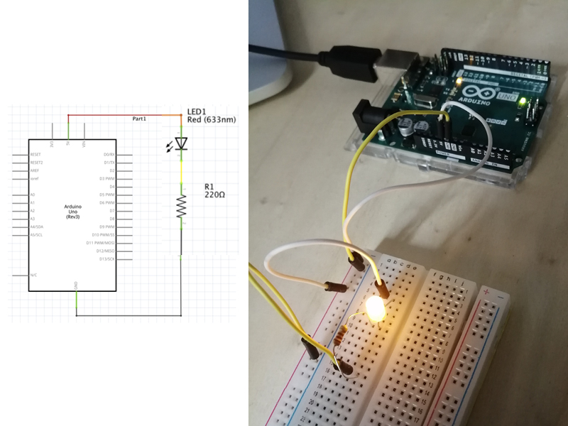
Materials :
Silver fabric
R = 220 Ohm
Blue LED 3.2V
Code example
int analog_sensor_pin = A0;   //change the pin, where the sensor is connected?
int analog_sensor_value = 0;
int led_pin = 3;


void setup() {
  // put your setup code here, to run once:
  pinMode(analog_sensor_pin, INPUT);
  pinMode(led_pin, OUTPUT);
  Serial.begin(9600);
!
}

void loop() {
  // put your main code here, to run repeatedly:
  analog_sensor_value = analogRead(analog_sensor_pin); //read the Voltage of the pin sensor

  analog_sensor_value = map(analog_sensor_value, 65, 72, 0, 255); //we change the range
  analog_sensor_value = constrain(analog_sensor_value, 0, 255); //we apply the limits

  analogWrite(led_pin, analog_sensor_value);  //we use the mapped value to control the Led
  Serial.println(analog_sensor_value); // print the value on the Serial monitor
  delay(10);

}
Digital embroidery to make soft circuit
The Friday, we decided to create a connective lightning pattern on felt. For that, we created a soft circuit with embroidery technique and we learned how to use the embroidery machine and its software : PE Design 11.
Goals :
- Integrate 3 LEDs in the circuit
- Make a digital sensor out of conductive thread for embroidery and conductive wire mesh
- Make a pocket for the battery
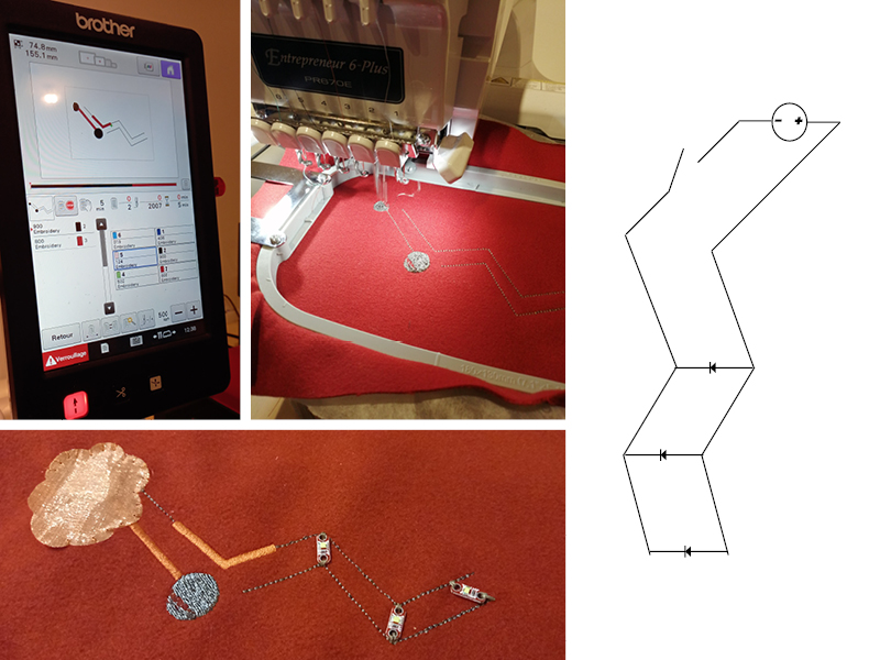
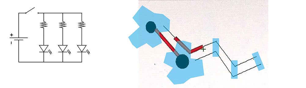
We wanted to put 3 LEDs in our circuit so we had to make a parallel circuit. First we drew a circuit sketch on paper and decided the materials what we used. As you can see on the picture below, we translated the circuit scheme for the embroidery. The blue parts (clouds and LEDs) were added after the embroidery by hand.
Materials :
- Alkaline 3V
- 3 LED SMT
- Copper fabrics
- Conductive yarns and non-conductive yarns
- Felt
Then we drew the pattern on PE design 11 with two color codes. One color code for the conductive yarn and an other for the non-conductive yarn. On this circuit we add two big embroidery points, one for to create the contact with the ground of battery and another to create the contact with the switch.
The conductive yarn is protected with an embroidery non-conductive on two part to do a good way circuit. One of two clouds in copper fabric, on circuit, is a momentary switch.
The other cloud in copper fabric is conductor between the power of the battery and the beginning of circuit.
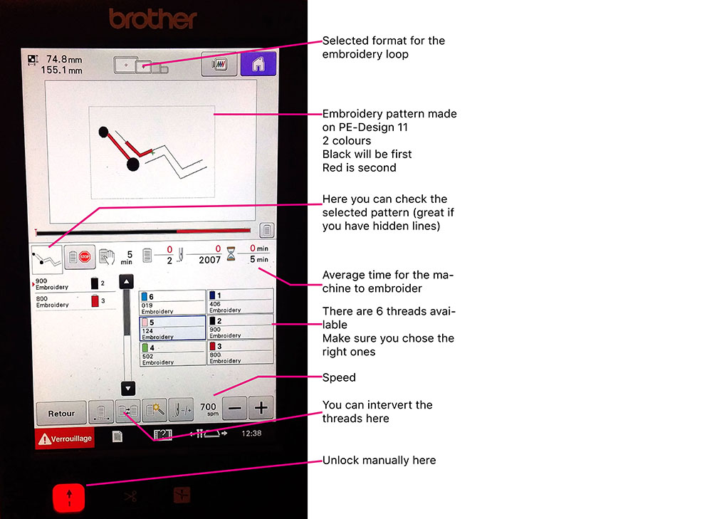
How to use a Digital Embroidery machine
We are working with the PE-Design 11 software and a PR670E Embroidery Machine. To start, open the software and follow the steps :
- chose the size of the embroidery loop : Design Settings > 100 x 120 mm
- draw your pattern using Shapes/Lines | Download your pattern (WMF format) : import > from vector image
- chose the colours wisely and check the order for the different embroideries (like if one is crossing another, which one do you want to be on top ?)
- if you don't want the embroidery machine to cut the thread at the end of the embroidery, use the small scissors icon
Once you're pattern is ready on PE-Design 11 you can save it on a USB key and upload the file on your embroidery machine.
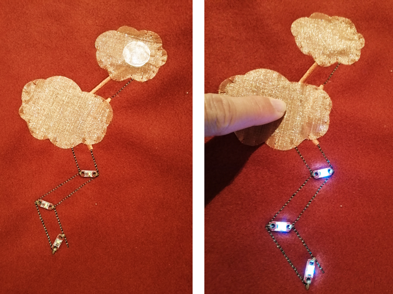
After the digital embroidery process, we sewed the leds on the circuit, sewed the the two copper fabric clouds and put the battery in the top cloud. The battery is like in a sandwich. The top cloud is the positive and under the cloud and the battery the grey embroidery is the negative.
Final outcome
Idea and inspiration
Also, this week, I started to think a project that I would like to develop during the wearable week.
I would like to create a connected jewel to add on a costume. For that, I spoke of this project with a friend that does clubkid show and performance and we would like collaborate together. I wish to develop an interactive jewel that would light up according the body movement of performer.
I would like to experiment accelerometer and stretch sensors, and a digital switch that activate lights in a random way.

To be continued… :)
Useful links
- Lecture – E-textiles – Liza Stark
- Basic electronics Tutorial - Emma Pareschi
- Sensors electronics Tutorial - Emma Pareschi
- Intro to Arduino tutorial - Emma Pareschi
- Review of the week