13. Skin Electronics

In the same way that the wearables industry is integrating fashion practices in their development, we envision new partnerships between the biotech/tech companies and skin professionals such as makeup artists, prosthesis experts and tattooists in order to embrace the idea of human-device symbiosis. FX e-makeup made use of special effects makeup for hiding electronic components that sense facial muscle movements, acting as a second skin.
Ressources
Katia Vega website : The referent of the week
"Can you change your make up automatically ?"
ChromoSkin
Kinisi Project By Katia Vega
ElectroDermis
Shop / Studio : Playtronica
Playtronica is an international team of musicians, technicians, and STEAM enthusiasts. Thier mission is to explore, inspire, and provoke curiosity using music, play, and creative possibility.
They propose different musical and interactive hardwares in their online shop.
Research & Work
This week, I focus how to use an ATtiny to can create different micro electronic circuit wearables.
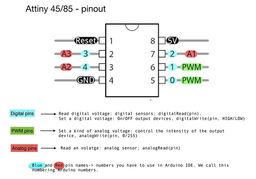
Sensing & Outputs - ATTINY - Part 1
ATtiny schema :
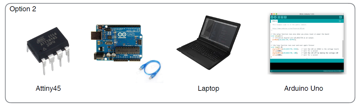
How to program an Attiny ?
ATtiny > Laptop
Need = ATtiny + Arduino UNO + USB cable + Arduino IDE
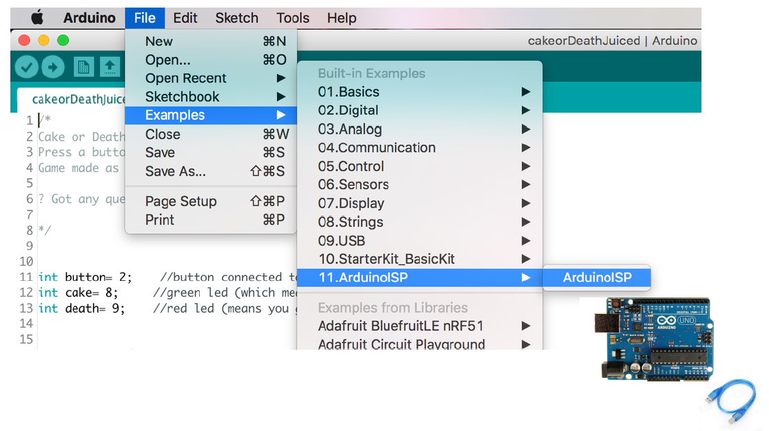
Transform Arduino UNO in programmer : upload the right code (ARDUINO ISP) in Arduino Uno :
File > Exemples > Arduino ISP
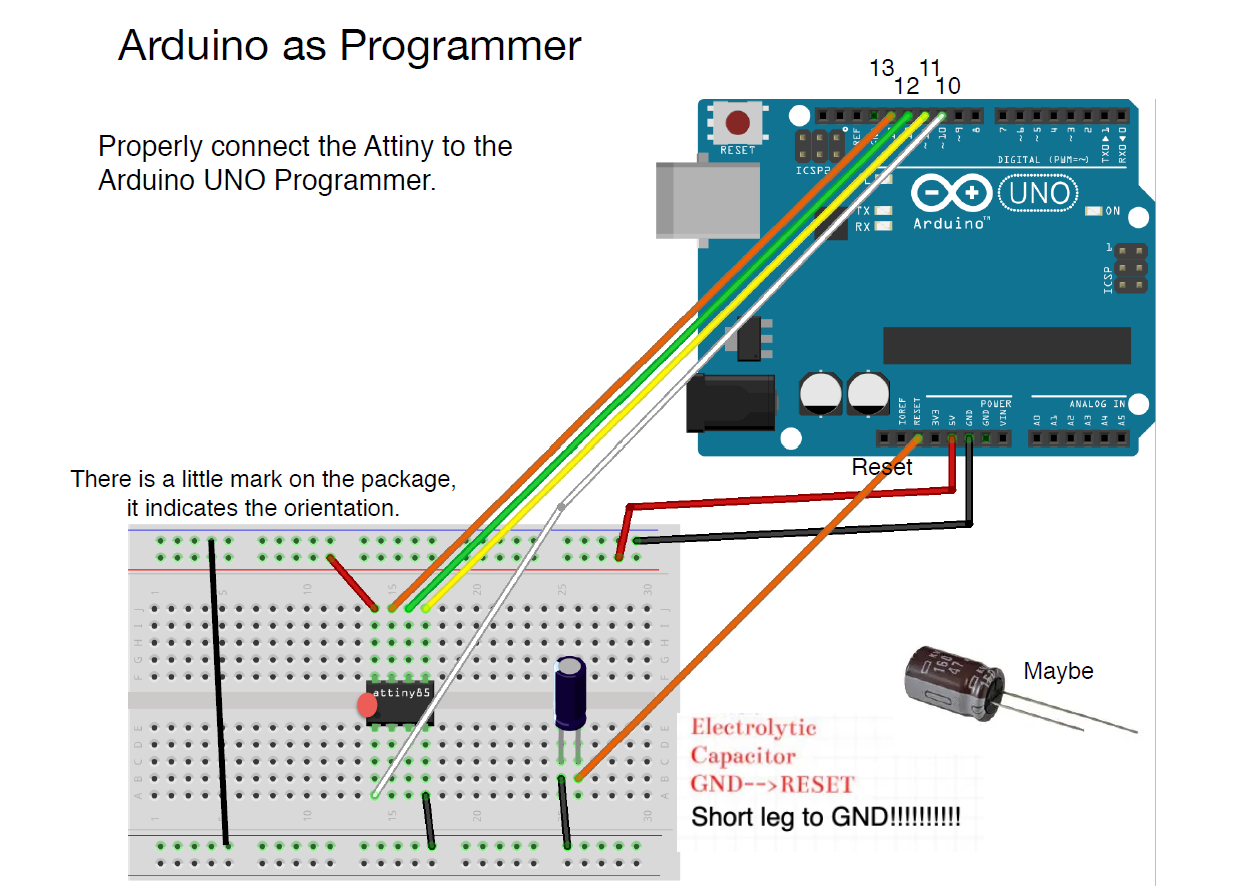
Then, build the cicruit with the ATtiny, the Arduino Uno and the laptop.
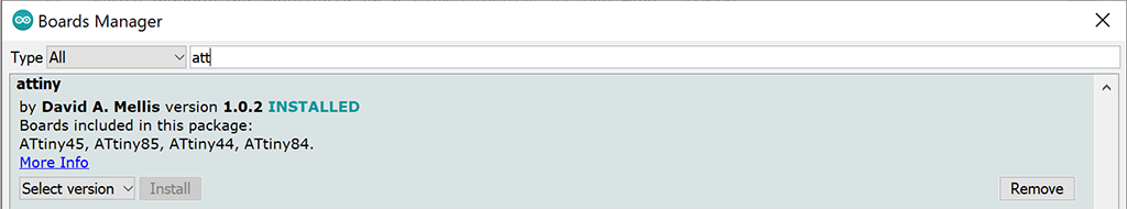
Install the Attiny Board in Arduino IDE :
Add this link :
https://raw.githubusercontent.com/damellis/attiny/ide-1.6.x-boards-manager/package_damellis_attiny_index.json
in : files > preferences > Additional Boards Manager URLs > OK
Then, in tools on Arduino :
Board > Boards manager > Install "attiny"
Also in tools :
↓ Check and select this setup ↓
Board > ATtiny Microcontrollers > ATtiny 25/45/85
Processors > ATtiny 85 (it depende of the ATtiny that is used)
Clock > Internal 8MHz
Port > Arduino UNO
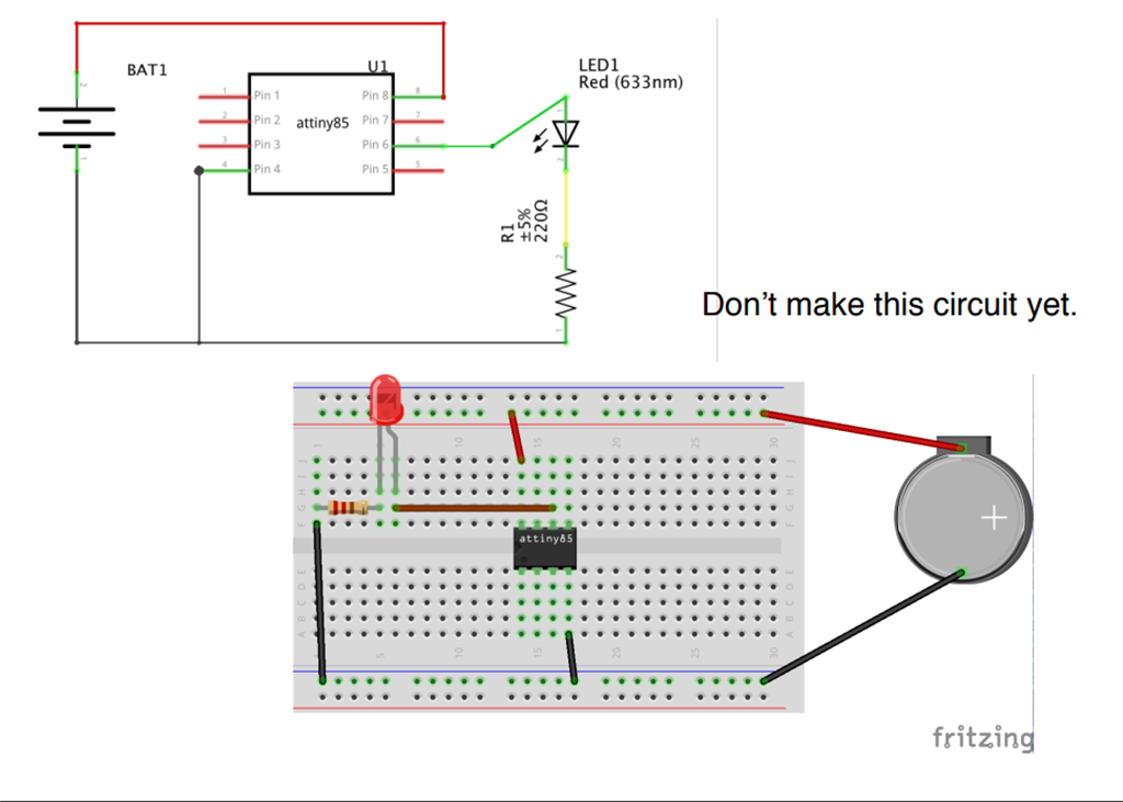
Attiny + Led
This schema circuit is not really right ! We need to combine this schema with the next schema.
Code exemple :
int led_pin = 1;  //pin of the Led

void setup() {
  // put your setup code here, to run once:
  pinMode(led_pin, OUTPUT);   // set the pin 3 as OUTPUT

}

void loop() {
  // put your main code here, to run repeatedly:
  digitalWrite(led_pin, HIGH);      //turn the Led ON
  delay(1000);                //wait
  digitalWrite(led_pin, LOW);       //turn the Led OFF
  delay(1000);                //wait
}
Attiny + Led + Switch
Code exemple :
// this constant won't change:
int  sw_pin = 4;    // the pin that the pushbutton is attached to

int led_pin = 1; //pin of the led

// Variables will change:
int sw_status = 0;         // current state of the button

void setup() {
  // initialize input and output pins:
  pinMode(sw_pin, INPUT_PULLUP);
  pinMode(led_pin, OUTPUT);

}

void loop() {

  // read the pushbutton input pin:
  sw_status = digitalRead(sw_pin);

  // compare the switch status to its previous state
  if (sw_status == LOW) {
    digitalWrite(led_pin, HIGH);
  } else {
    digitalWrite(led_pin, LOW);
  }

}
Attiny + Neopixel + Switch
Code exemple : (nota : to use a neopixel don't forget to use "Adafruit NeoPixel" language as we saw during the Wearable week)
#include <Adafruit_NeoPixel.h>
// A basic everyday NeoPixel strip test program.

// NEOPIXEL BEST PRACTICES for most reliable operation:
// - Add 1000 uF CAPACITOR between NeoPixel strip's + and - connections.
// - MINIMIZE WIRING LENGTH between microcontroller board and first pixel.
// - NeoPixel strip's DATA-IN should pass through a 300-500 OHM RESISTOR.
// - AVOID connecting NeoPixels on a LIVE CIRCUIT. If you must, ALWAYS
//   connect GROUND (-) first, then +, then data.
// - When using a 3.3V microcontroller with a 5V-powered NeoPixel strip,
//   a LOGIC-LEVEL CONVERTER on the data line is STRONGLY RECOMMENDED.
// (Skipping these may work OK on your workbench but can fail in the field)

// Which pin on the Arduino is connected to the NeoPixels?
// On a Trinket or Gemma we suggest changing this to 1:
#define LED_PIN    1

// How many NeoPixels are attached to the Arduino?
#define LED_COUNT 5

// Declare our NeoPixel strip object:
Adafruit_NeoPixel strip(LED_COUNT, LED_PIN, NEO_GRB + NEO_KHZ800);
// Argument 1 = Number of pixels in NeoPixel strip
// Argument 2 = Arduino pin number (most are valid)
// Argument 3 = Pixel type flags, add together as needed:
//   NEO_KHZ800  800 KHz bitstream (most NeoPixel products w/WS2812 LEDs)
//   NEO_KHZ400  400 KHz (classic 'v1' (not v2) FLORA pixels, WS2811 drivers)
//   NEO_GRB     Pixels are wired for GRB bitstream (most NeoPixel products)
//   NEO_RGB     Pixels are wired for RGB bitstream (v1 FLORA pixels, not v2)
//   NEO_RGBW    Pixels are wired for RGBW bitstream (NeoPixel RGBW products)

uint32_t off = strip.Color(0, 0, 0);

int sw_pin = 2;
int sw_status = 0;


// setup() function -- runs once at startup --------------------------------

void setup() {

  strip.begin();           // INITIALIZE NeoPixel strip object (REQUIRED)
  strip.show();            // Turn OFF all pixels ASAP
  strip.setBrightness(50); // Set BRIGHTNESS to about 1/5 (max = 255)

  pinMode(sw_pin, INPUT_PULLUP);

}


// loop() function -- runs repeatedly as long as board is on ---------------

void loop() {

   sw_status = digitalRead(sw_pin);

   if (sw_status == 0){
      colorWipe(strip.Color(255,   0,   0), 50); // Red
      strip.fill(off, 0, 10);
      strip.show();  //display the color
    }
}

// Fill strip pixels one after another with a color. Strip is NOT cleared
// first; anything there will be covered pixel by pixel. Pass in color
// (as a single 'packed' 32-bit value, which you can get by calling
// strip.Color(red, green, blue) as shown in the loop() function above),
// and a delay time (in milliseconds) between pixels.
void colorWipe(uint32_t color, int wait) {
  for(int i=0; i<strip.numPixels(); i++) { // For each pixel in strip...
    strip.setPixelColor(i, color);         //  Set pixel's color (in RAM)
    strip.show();                          //  Update strip to match
    delay(wait);                           //  Pause for a moment
  }
}
Sensing & Outputs - ATTINY - Part 2
To prepare the second tutorial :
To Pressure matrix code : 3x3 PAPER MATRIX EXAMPLE

To read data (analog sensor) with the micro controler on the PC, we can't to use Arduino UNO, we need an other hardware : FTDI chip*
*What is a data : the quantites, caracters, or symbols on witch operations are performed by a computer. Electronical informations / signals.
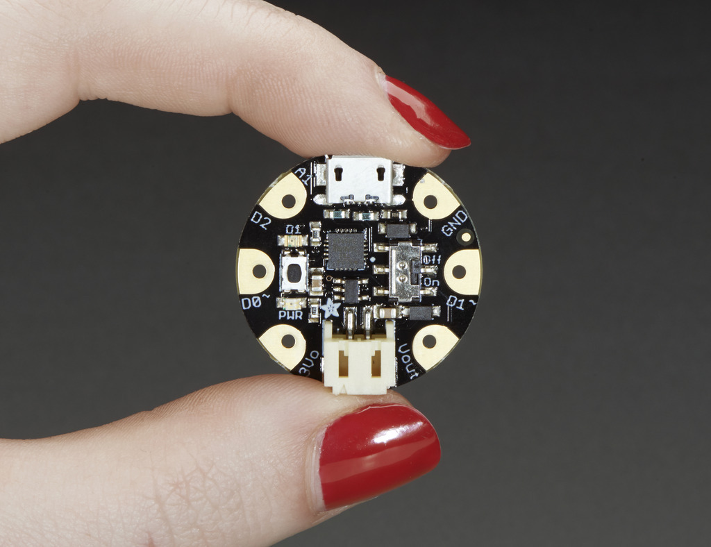
GEMMA Hardware : Adafruit's mini controller. It is an ATtiny breakout board - No need a programmer.
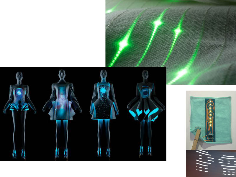
Project
An interactive clubkid costume with lights :
As I explained during the wearable week : during the next months I will create a constume with this new skills. I will collaborate with a friend witch do dragshows.
To create this project, I needed to know how to use the ATtiny, to propose an electronic wearable costume.
Inspiration
Work and Ressources
ATTINY POV by Hannah
ATTINY POV on Kobakant
Material that I need :
- Lipo baterry
- Neopixels
- Arduino UNO (if ATtiny)
- Digital sensor
- Conductive yarn
- ATtiny (or) GEMMA Hardware
Useful links
- Lecture of the week - Katia Vega
- Tutorial Part 1 - Sensing and outputs - Emma Pareschi
- Tutorial Part 2 - Sensing and outputs - Emma Pareschi
- Tutorial Part 3 - Sensing and outputs - Emma Pareschi