9. Wearables
Research
Wearable technology combines electronics, materials science, and design to create functional items that can be worn comfortably on the body while providing technological utility. This includes smart textiles, embedded sensors, conductive materials, and energy solutions.
Material and Design considerations
-
Durability: It must withstand stretching, bending and daily wear
-
Washability: Electronics need protection from water and detergent damage
-
Comfort: Lightweight, breathable fabric that does not irritate skin
-
Sustainability: Use of biodegradable materials, recycled textiles and low-energy production methods.
Sustainability approaches
-
Material innovation such as organic cotton, bamboo, biodegradable polymers.
-
Energy efficiency- harvesting body heat or motion to power devices
-
Lifecycle design- easy disassembly for recycling or repair.
Examples
1) Smart fitness bands measuring heart rate and activity.
2) E-textile shirts tracking posture or respiration
3) Smart shoes
4) Temperature regulating fabric.
## Reference and Inspiration
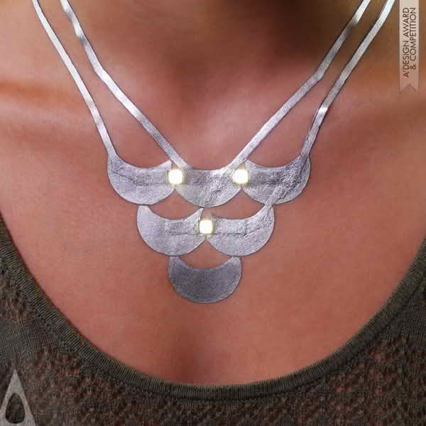
Cindy Hsin-Liu Kao work helps in bridging technology,textile, wearability and human-centered design
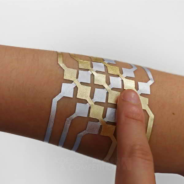 {width=200 align=left }
Asha Peta Thompson creates smart textile fabrics by embedding sensors. One of her works is the e-uniforms for infantry.
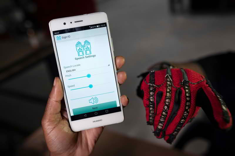
In Kenya, Roy Allela invented smart gloves that convert hand signs to audio speech.
Tools and materials
- Two 3v batteries
- Transistors
- LEDs
- Jumper wires
- Resistors
- Arduino IDE
- ESP 32C3
- Touch sensor
- Vibration sensor
- XIAO ESP32C3
- Phone
- LEDs
- Copper tape
- Connecting wires
- Insulating tape
- Double sided tape
- solderin iron and gun
- OTG Cable
Process and workflow
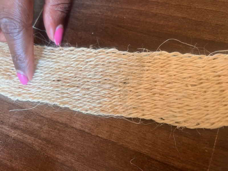
My intention for this week is to create a bracelet made from sisal material with three small LED lights clusters placed evenly around it. The LEDs should light up when I’m walking or moving, and remain off when I'm still. The bracelet will be lightweight, wearable, and safe.
Inside the bracelet, I plan to include a vibration sensor and connected to the LEDs and a tiny battery. When the sensor detects movement such as walking, the circuit will activate and the LEDs will turn on. When movement stops, the lights should fade or turn off.
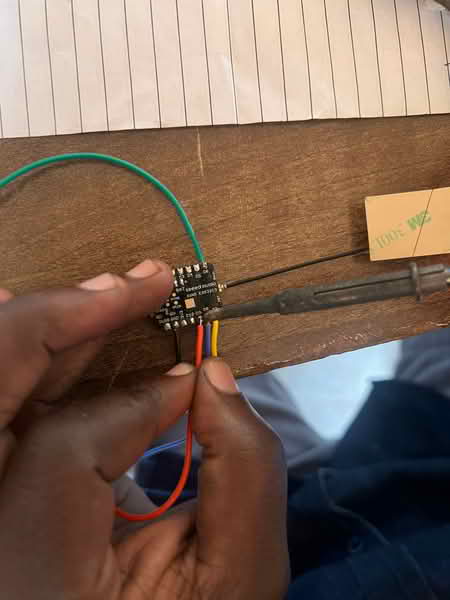
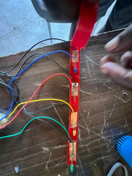
I then gathered all the eletronic components to be used and made a conection:
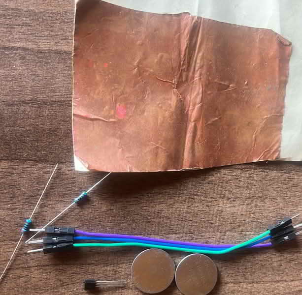
 {width= 270 align= right}
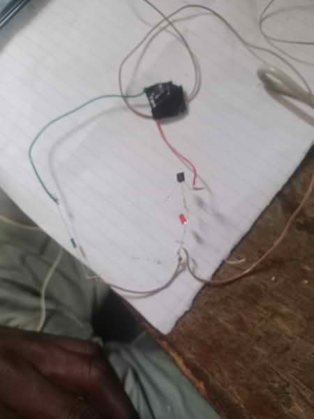
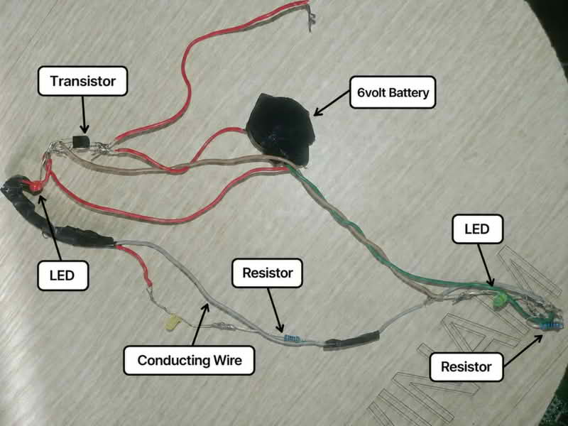
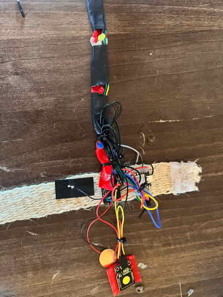
I used copper tape to assemble all the electronics together and sealing the wires with a black tape.
I attached the assembled electronics and the LED were functioning as needed
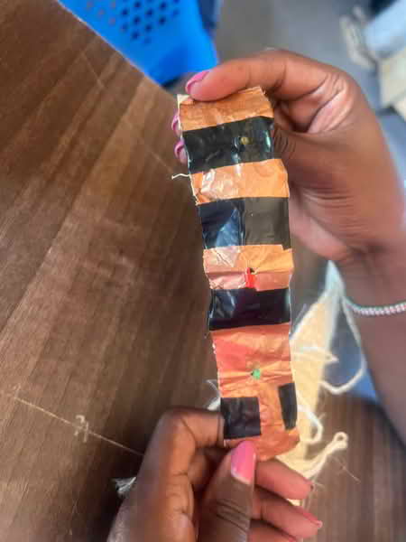
I mounted them on my sisal bracelet. Whenever it comes in contact with the skin, it sends signal and the LED bulbs light.
I needed to make another swatch that now I could be able to move freely.
Steps
-
Cut copper tape into strips and remove sticker from one side to distinguish the +ve and -ve terminals
-
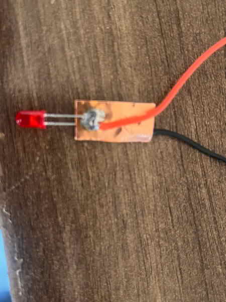
Solder the LEDs to the copper tape
- Connect the resistors to the -ve terminal
- Use black connecting wires to link to -ve terminal and colored connecting wires to the +ve
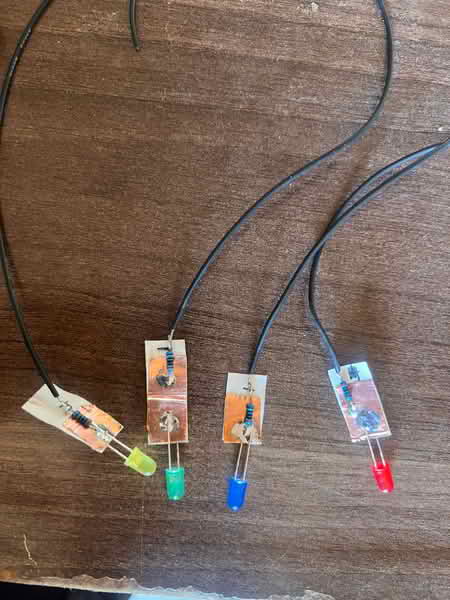
-
Test if the LEDs work.
-
Mount the LEDs +ve terminal to the ESP32C3 pins.
Used this code to as a test
'''
define LED1 6
define LED2 7
define LED3 8
define LED4 9
void setup() { pinMode(LED1, OUTPUT); pinMode(LED2, OUTPUT); pinMode(LED3, OUTPUT); pinMode(LED4, OUTPUT); }
void loop() {
// One by one digitalWrite(LED1, HIGH); delay(300); digitalWrite(LED1, LOW); digitalWrite(LED2, HIGH); delay(300); digitalWrite(LED2, LOW); digitalWrite(LED3, HIGH); delay(300); digitalWrite(LED3, LOW); digitalWrite(LED4, HIGH); delay(300); digitalWrite(LED4, LOW);
delay(500);
// All ON digitalWrite(LED1, HIGH); digitalWrite(LED2, HIGH); digitalWrite(LED3, HIGH); digitalWrite(LED4, HIGH); delay(500);
// All OFF digitalWrite(LED1, LOW); digitalWrite(LED2, LOW); digitalWrite(LED3, LOW); digitalWrite(LED4, LOW); delay(500); } '''
I noticed the pins are not as they should be....like pin 5 in code is pin3 on board. I wanted the pins to blink one at a go in a sequential manner. This is was unique with the microcontroller I was using. Instead, the ESP32 Pin is integrated in this manner.
| Board Label | GPIO (use in code) |
|---|---|
| D0 | 2 |
| D1 | 3 |
| D2 | 4 |
| D3 | 5 |
| D4 | 6 |
| D5 | 7 |
| D6 | 21 |
| D7 | 20 |
| D8 | 8 |
| D9 | 9 |
| D10 | 10 |
CODE
'''
define LED1 21
define LED2 20
define LED3 8
define LED4 9
int delayTime = 120;
void setup() { pinMode(LED1, OUTPUT); pinMode(LED2, OUTPUT); pinMode(LED3, OUTPUT); pinMode(LED4, OUTPUT); }
void loop() {
// Forward chase digitalWrite(LED1, HIGH); delay(delayTime); digitalWrite(LED1, LOW); digitalWrite(LED2, HIGH); delay(delayTime); digitalWrite(LED2, LOW); digitalWrite(LED3, HIGH); delay(delayTime); digitalWrite(LED3, LOW); digitalWrite(LED4, HIGH); delay(delayTime); digitalWrite(LED4, LOW);
// Reverse chase digitalWrite(LED4, HIGH); delay(delayTime); digitalWrite(LED4, LOW); digitalWrite(LED3, HIGH); delay(delayTime); digitalWrite(LED3, LOW); digitalWrite(LED2, HIGH); delay(delayTime); digitalWrite(LED2, LOW); digitalWrite(LED1, HIGH); delay(delayTime); digitalWrite(LED1, LOW); } '''
I assembled the electronics together on my sisal bracelet
Mounting the sensors using glue gun
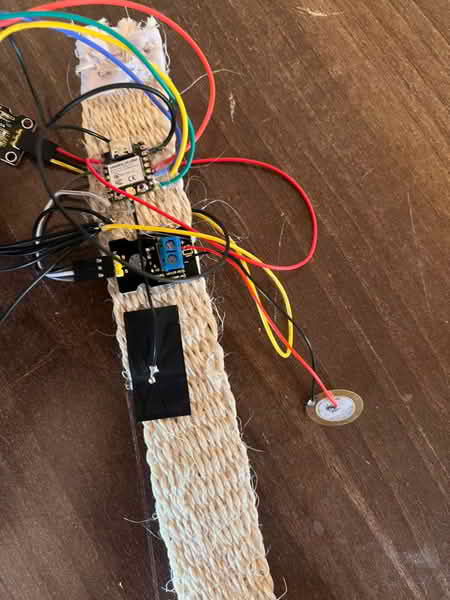
Assembled the LEDs using double sided tape
Connected the LEDs with the microcontroller
I then wore the bracelet, by tying the LEDs on my arm using cable ties
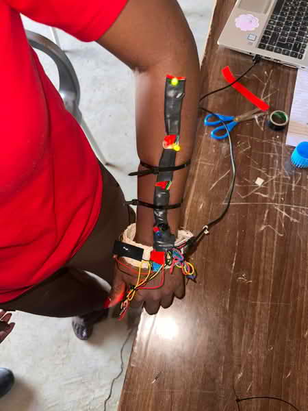
Then I powered using my phone making it easier for me to walk around
I did wed intergration:
The following code generated by ChatGPT was used and it integrated web UI:
#include <WiFi.h>
#include <WebServer.h>

// ---------------- PINS ----------------
#define TOUCH_PIN 2
#define VIB_PIN 3

#define LED1 21
#define LED2 20
#define LED3 8
#define LED4 9

// ---------------- WIFI ----------------
const char* ssid = "SKIN";
const char* password = "12345678";

WebServer server(80);

// ---------------- SENSOR STATES ----------------
int touchState = 0;
int vibState = 0;

// vibration memory
unsigned long lastVibTime = 0;
int vibBurstCount = 0;

// ---------------- LIVING WEB UI ----------------
String page = R"rawliteral(

<!DOCTYPE html>
<html>
<head>
<meta name="viewport" content="width=device-width, initial-scale=1">
<title>Living Skin</title>

<style>
body {
  margin:0;
  font-family: Arial;
  color:white;
  text-align:center;
  transition:0.2s;
  background:#0b0f14;
}

body.idle {
  animation: breathe 4s infinite;
}

@keyframes breathe {
  0% { background:#0b0f14; }
  50% { background:#111a24; }
  100% { background:#0b0f14; }
}

.touch { background:#123a2a !important; }
.flash { background:white !important; color:black !important; }

.stress {
  animation: shake 0.1s infinite;
  background:#2a0b0b !important;
}

@keyframes shake {
  0% { transform:translate(0px,0px); }
  25% { transform:translate(2px,-2px); }
  50% { transform:translate(-2px,2px); }
  75% { transform:translate(2px,2px); }
  100% { transform:translate(0px,0px); }
}

.box {
  margin:20px;
  padding:20px;
  border-radius:12px;
  background:rgba(255,255,255,0.05);
}

.big { font-size:28px; }
</style>
</head>

<body id="body">

<h2>🧠 Living Skin System</h2>

<div class="box">🖐 Touch: <span id="touch">0</span></div>
<div class="box">⚡ Vibration: <span id="vib">0</span></div>

<div class="box big" id="state">IDLE</div>

<script>

let vibCount = 0;
let lastVibTime = 0;

function updateUI(touch, vib) {

  let body = document.getElementById("body");
  let state = document.getElementById("state");

  body.className = "idle";

  let now = Date.now();

  if (touch == 1) {
    body.classList.add("touch");
    state.innerHTML = "🖐 AWARE";
  }

  if (vib == 1) {
    body.classList.add("flash");
    state.innerHTML = "⚡ REFLEX";

    if (now - lastVibTime < 300) vibCount++;
    else vibCount = 1;

    lastVibTime = now;
  }

  if (vibCount > 4) {
    body.className = "stress";
    state.innerHTML = "🔥 STRESS";
  }

  if (touch == 0 && vib == 0) {
    state.innerHTML = "🌬 BREATHING";
  }
}

setInterval(() => {
  fetch('/data')
  .then(r => r.json())
  .then(d => {
    document.getElementById("touch").innerHTML = d.touch;
    document.getElementById("vib").innerHTML = d.vib;
    updateUI(d.touch, d.vib);
  });
}, 150);

</script>

</body>
</html>

)rawliteral";

// ---------------- SERVER ----------------
void handleRoot() {
  server.send(200, "text/html", page);
}

void handleData() {
  String json = "{";
  json += "\"touch\":" + String(touchState) + ",";
  json += "\"vib\":" + String(vibState);
  json += "}";
  server.send(200, "application/json", json);
}

// ---------------- LED EFFECTS ----------------
void allOff() {
  digitalWrite(LED1, LOW);
  digitalWrite(LED2, LOW);
  digitalWrite(LED3, LOW);
  digitalWrite(LED4, LOW);
}

void wave() {
  digitalWrite(LED1, HIGH); delay(60); digitalWrite(LED1, LOW);
  digitalWrite(LED2, HIGH); delay(60); digitalWrite(LED2, LOW);
  digitalWrite(LED3, HIGH); delay(60); digitalWrite(LED3, LOW);
  digitalWrite(LED4, HIGH); delay(60); digitalWrite(LED4, LOW);
}

void flash() {
  digitalWrite(LED2, HIGH);
  digitalWrite(LED3, HIGH);
  delay(50);
  allOff();
}

void burst() {
  for (int i = 0; i < 3; i++) {
    digitalWrite(LED1, HIGH);
    digitalWrite(LED2, HIGH);
    digitalWrite(LED3, HIGH);
    digitalWrite(LED4, HIGH);
    delay(80);
    allOff();
    delay(80);
  }
}

// ---------------- SETUP ----------------
void setup() {
  Serial.begin(115200);

  pinMode(TOUCH_PIN, INPUT);
  pinMode(VIB_PIN, INPUT);

  pinMode(LED1, OUTPUT);
  pinMode(LED2, OUTPUT);
  pinMode(LED3, OUTPUT);
  pinMode(LED4, OUTPUT);

  WiFi.softAP(ssid, password);

  Serial.println("WiFi Started");
  Serial.println(WiFi.softAPIP());

  server.on("/", handleRoot);
  server.on("/data", handleData);
  server.begin();
}

// ---------------- LOOP ----------------
void loop() {

  touchState = digitalRead(TOUCH_PIN);
  vibState = digitalRead(VIB_PIN);

  server.handleClient();

  // ---------------- PHYSICAL BEHAVIOR ----------------

  if (touchState == HIGH && vibState == HIGH) {
    burst();
  }
  else if (touchState == HIGH) {
    wave();
  }
  else if (vibState == HIGH) {
    flash();
  }

  delay(10);
}
Steps to follow to connect to web server for live streaming
-
Connect phone or PC to the wifi and change wifi name to ESP32-SKIN password:12345678
-
Open browser and insert the wifi IP address provided in the serial monitor and browse.
live touches,and vibration and real time system update will be displayed.