12. Skin Electronics
Research
Skin Electronics – Summary
Over the past weeks, I have explored e-textiles and wearable technologies, learning how electronics can be integrated into fabrics and everyday clothing. This journey introduced me to foundational electronic skills—designing circuits, stitching conductive threads, embedding sensors, and creating interactive garments. Each step expanded my understanding of how technology can be worn, how it can sense the body, and how it can respond to movement, touch, or environment.
Now, I am taking a deeper step into the next frontier of wearable technology: skin electronics. Unlike wearables stitched onto clothing, skin electronics bring the interface even closer to the body. They are ultra-thin, flexible, stretchable devices that sit directly on the skin like a temporary tattoo or a soft patch. This week, I aim to explore how electronics can meaningfully interact with the skin, both functionally and safely.
Skin electronics combine materials science, digital fabrication, and biomedical principles. They can monitor real-time physiological signals such as temperature, hydration, heart rate, sweat composition, and muscle activity. Because they move with the skin, they feel natural. These technologies inspire new possibilities for health monitoring, sports performance, personal expression, and human–machine interfaces.
Week's Assignment


Tools and Materials
- [Arduino UNO](http://class.textile-academy.org)
- [Arduino IDE](http://class.textile-academy.org)
- Jumper wires
- Hall effect sensor
- Touch sensor
- Vibration sensor
- XIAO ESP32C3
- Phone
- LEDs
- Copper tape
- Connecting wires
- Insulating tape
Process and workflow
I used hall effect sensor to detect magnetic field. I wanted to use it in sensing position changes and speed detection using a magnet.
First I had to code it in ArduinO IDE and connecting the sensor to arduino UNO.
After connecting all the electronic components together, I linked the arduino UNO to my computer to get the readings and code. I had to ensure I was using the correct board port and I had to check in with my device manager.

 I used the following code.
Code
int sensorPin = 11; // Hall sensor signal pin
int ledPin = 7;    // LED pin

int sensorValue; // current sensor state
int lastSensorValue = 1;     // previous sensor state
int count = 0;               // counts magnet passes

void setup() {
  Serial.begin(1200);
  pinMode(sensorPin, INPUT);
  pinMode(ledPin, OUTPUT);
}

void loop() {
  sensorValue = digitalRead(sensorPin);  // Detect magnet pass (HIGH -> LOW transition)
  if (sensorValue == 0 && lastSensorValue == 1) {
    count++;
    Serial.print("Magnet Pass Count: ");
    Serial.println(count);
    digitalWrite(ledPin, HIGH);   // LED ON
  }

  // Turn LED OFF when magnet goes away
  if (sensorValue == 1) {
    digitalWrite(ledPin, LOW);
  }

  lastSensorValue = sensorValue;
  delay(50);
When a magnet comes close → sensor outputs HIGH (1) When magnet moves away → sensor outputs LOW (0).
I also programmed it to count the number of passes when it detects the magnet.

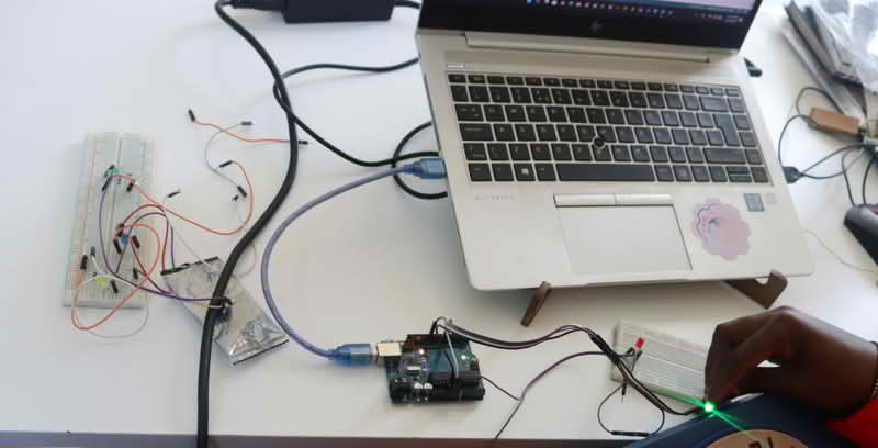
I am to use this code on a car seat to know how far the seat has moved, to know proximity of the driver to the seat when in motion.
I made a motion responsive hair illumination trial.
I programmed gyro sensor into a Xiao ESP-32C3 microcontroller with 5 LED lights. First I did a trial on breadboard
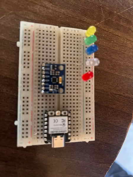
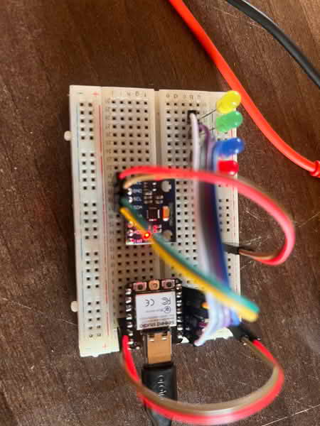
I connected all the componets to the breadboard and generated the code from ChatGPT
#include <Wire.h>

#define LED1 D0
#define LED2 D1
#define LED3 D2
#define LED4 D3

void setup() {
  Serial.begin(115200);

  pinMode(LED1, OUTPUT);
  pinMode(LED2, OUTPUT);
  pinMode(LED3, OUTPUT);
  pinMode(LED4, OUTPUT);

  Wire.begin(6, 7);

  // Wake MPU6050
  Wire.beginTransmission(0x68);
  Wire.write(0x6B);
  Wire.write(0);
  Wire.endTransmission();

  Serial.println("MPU6050 Ready");
}

void loop() {

  Wire.beginTransmission(0x68);
  Wire.write(0x3B);
  Wire.endTransmission(false);

  Wire.requestFrom(0x68, 6);

  int16_t ax = (Wire.read() << 8) | Wire.read();
  int16_t ay = (Wire.read() << 8) | Wire.read();
  int16_t az = (Wire.read() << 8) | Wire.read();

  // Calculate tilt magnitude
  int tilt = sqrt((long)ax * ax + (long)ay * ay);

  Serial.print("Tilt = ");
  Serial.println(tilt);

  // Turn all LEDs off
  digitalWrite(LED1, LOW);
  digitalWrite(LED2, LOW);
  digitalWrite(LED3, LOW);
  digitalWrite(LED4, LOW);

  if (tilt > 3000) digitalWrite(LED1, HIGH);
  if (tilt > 6000) digitalWrite(LED2, HIGH);
  if (tilt > 9000) digitalWrite(LED3, HIGH);
  if (tilt > 12000) digitalWrite(LED4, HIGH);

  delay(50);
}
To attach it onto my skin I had to transfer all the componets from breadboard and wire them. I used soldering to connect the LEDs to the microcontroller and the gyro sensor.
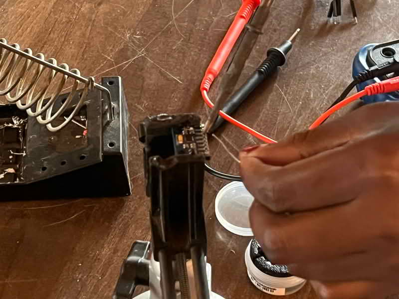
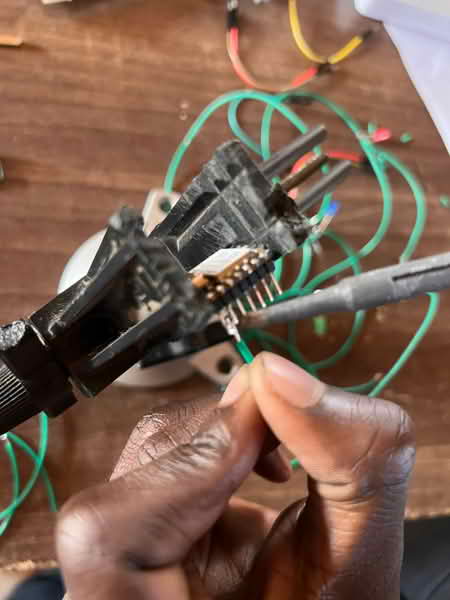
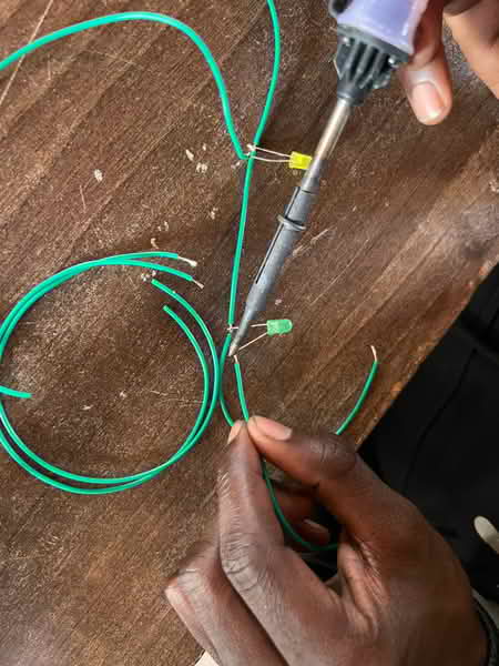
The next step was to braid the electronic componets to my hair and ensure the wires are invisible. The LEDs were put near the front of the hair for visibility.
The xiao ESP32C3 was powered by a rechargeable battery and was put at the back of the head

When tilting the head to the side, the LEDs function by going ON and OFF.
The reading from the serial monitor was as below