9. Wearables
Wearables
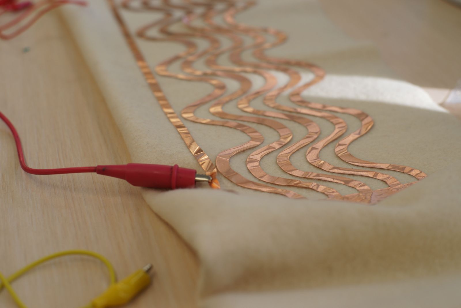 Photo by Svetlana Khachatryan
Research
Integrating electronics in wearables can stretch from being fun and playful, to serious and life changing. Throughout the week I decided to try both. I initially had had an idea to create a custom made thermo wear for myself. This would be something that could ease my life on days that I have FMF attacks. However, making soft speakers and playing with conductive embroidery was not something I was willing to give up!
References & Inspiration
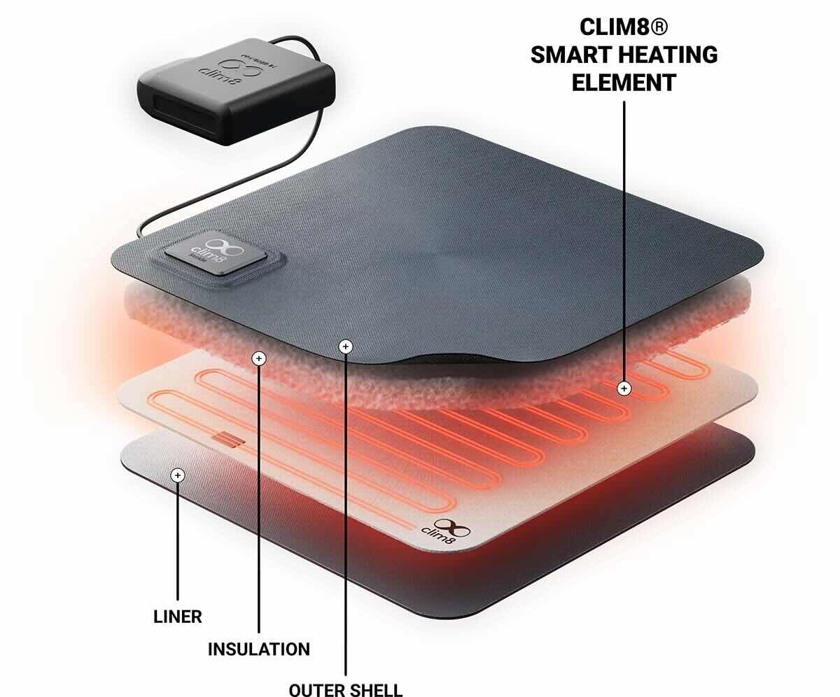
My Clim8

Clim8 uses a smart, sensor driven thermal system, which measures the temperature of your skin, the environment around you, your activity level and heats up your clothing according to your data profile. You can control your wearables through their application via bluetooth. It uses a battery to power it, however the data analisys is flexible and you do not need to constantly regulate it. Due to its many sensors a processor that analyses the data, it only uses the battery when you are wearing it and when you need the heat. It will automatically go to sleep when heat application is no longer needed. Flexible conductive elements are used to turn power into heat.
LilyPad Embroidery
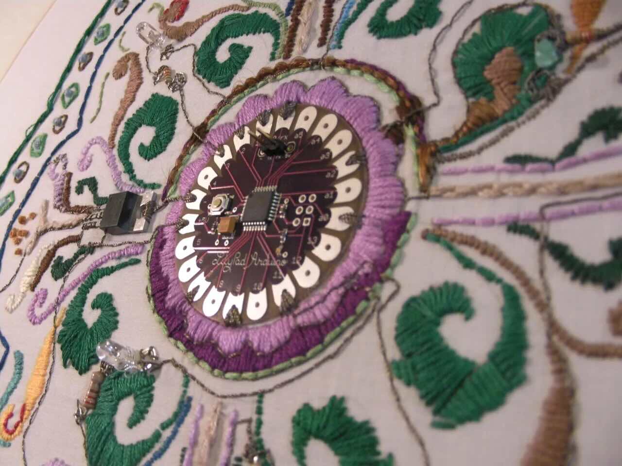
This embroidery is such a beautiful example of how wearable electronics can be almost invisible. Also conductive threads always put a smile on my face, since I love to slow stitch!
CuteCircuit

The Hug Shirt is another beautiful example of how electronics can be imbedded into garments. You can send hugs to a friend through this shirt, wherever they are (if of course they too own the same shirt). Embedded in the Hug Shirt® there are actuators that recreate the sensation of touch and the emotion of a hug to the Hug Shirt® of a distant loved one.
Tools
- Copper wire
- 9V battery
- 3.7 V LiPo battery
- Permanent magnet
- Stainless steel conductive thread
- W1209 thermostat module
- Alligator clips
- Medium to light cotton fabric
- Instek GPD-3303D Triple-Output Linear D.C. Power Supply
- Thermochromatic paint
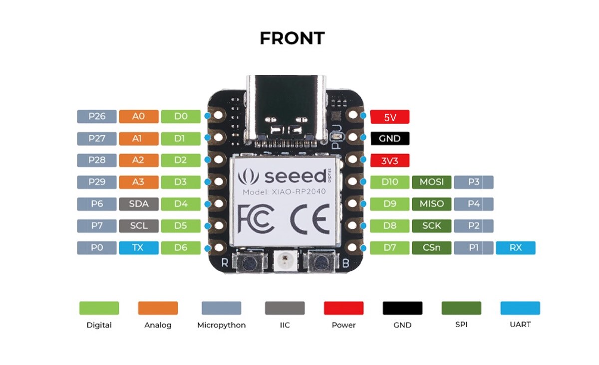
- Seeed Xiao RP2040
- MOSFET
- Resistor
- Diode
- Conductive textile
Flipping Magnet
To make a flipping magnet you will need enough copper wire to wrap around a pen 50-100 times, with two ends stretched out. It is important to sand the ends of the wire and burn it with a lighter, to expose the metal and make it conductive.
Place your permanent magnet on top of the coil. Take two alligator clips and connect to a 9V battery. Connect one of the alligator clips already attached to the battery to one end of the copper wire. Carefully connect the other alligator clip to the other end of the copper wire.. once the circuit is closed your magnet should flip!
Making A Circuit
MOSFET Transistor
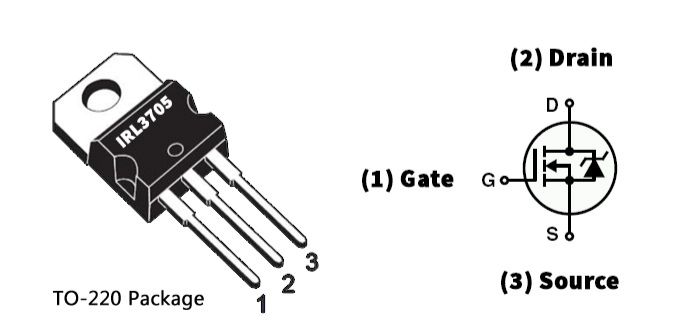
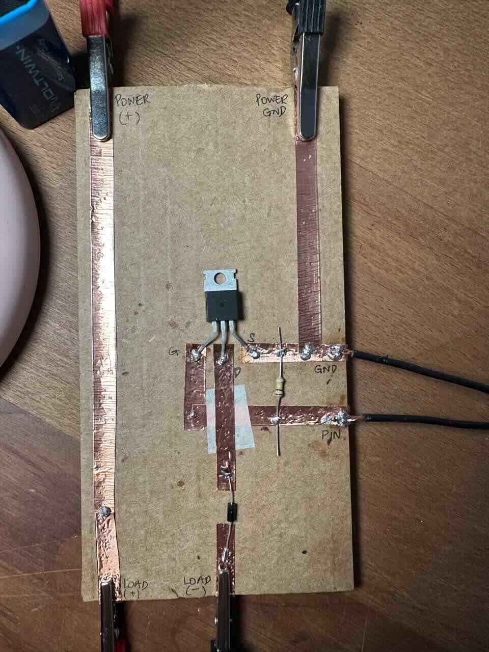
A MOSFET transistor is an electronic switch or amplifier. It has three gates - G (Gate), D (Drain), S (Source). When Voltage is applied to the Gate, it will create an electric field, which then will either open or close the path between Source and Drain. There are two types of MOSFETs. An N-channel MOSFET, which is what we will use, will conduct when a positive voltage passes through the gate. There are numerous MOSFETS and choosing the right one that will work with the Fabrixiao was a little hard to come by. The best MOSFET you can use with the Fabrixiao board RP 2040 is IRLB8721, however the closest one I could find was IRL3705. This is also an N-channel logic level with a Vgs min 1 - max 2.
Diode 1N4001
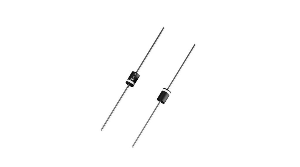
A 1N4001 diode is a commonly used diode, used for power and protection. In this case, it is used to protect the MOSFET from overheating and damage. It must be placed with the stripe (cathode) to Load (+).
The Debate
I used Liza Stark's circuit this week, which worked fine for me. However, Emma Pareschi suggested the same circuit, but with the diode to stretch from Load (+) to Load (-). She indicated that the diode makes no difference when connected as seen in my circuit.
When the diode is placed between D and Load (-), it does not act as a flyback diode and does not protect the MOSFET from overheating. It just sits there like a one way valve and allows high voltage spike travel straight back into the MOSFET.
When placed between Load (+) to Load (-), the cathode (silver stripe) connected to Load (+) and anode to Load (-), it allows the inductive spike to dissipate through the diode rather than frying the MOSFET.
Moving Magnet
After making the circuit, I was ready to test the code that Emma Pareschi provided to give the coil used in the flip magnet experiment. When the coil is placed over the magnet and connected to the circuit, powered by battery and coded with Arduino IDE through Fabrixiao board, it's supposed to move and stop then move again. This is achieved by using the Gate of the transistor. The pin will supply the Gate with 3.3V then 0V.
void setup() {
  // put your setup code here, to run once:
  pinMode(D8, OUTPUT);
}

void loop() {
  // put your main code here, to run repeatedly:
  digitalWrite(D8, HIGH); //=> 3.3V
  delay(1000);
  digitalWrite(D8, LOW); //=> 0V
  delay(1000);
}
When I initially tried it, it didn't work, so I had to debug it by checking the voltage using the multimeter. I initially checked my battery to make sure that it has not died, it showed 8.9V. I checked the Gate of the transistor - which was going from 3V to 0V, showing me that the code is working. I checked the Load as well. Everything seemed to be connected fine and my alligators worked too. However my magnet was not attracting the coil.
Using multimeter to check if the Arduino IDE code is working
My coil is 3 Ohms and I have a 9V battery. If I use Ohm's law then I=V(9)/R(3) = 3 amperes. However, the magnet did not move. I assume that in theory everything was correct, but in practice my coil was not getting strong enough current—possibly due to limitations of the transistor or power supply. Therefore, increasing the resistance of the coil or lowering the voltage would not solve the problem, as this would further reduce the current and weaken the magnetic field.
Second Experiment
Back in the lab, I made a second circuit using MOSFET IRLB8721, once I was able to acquire it.
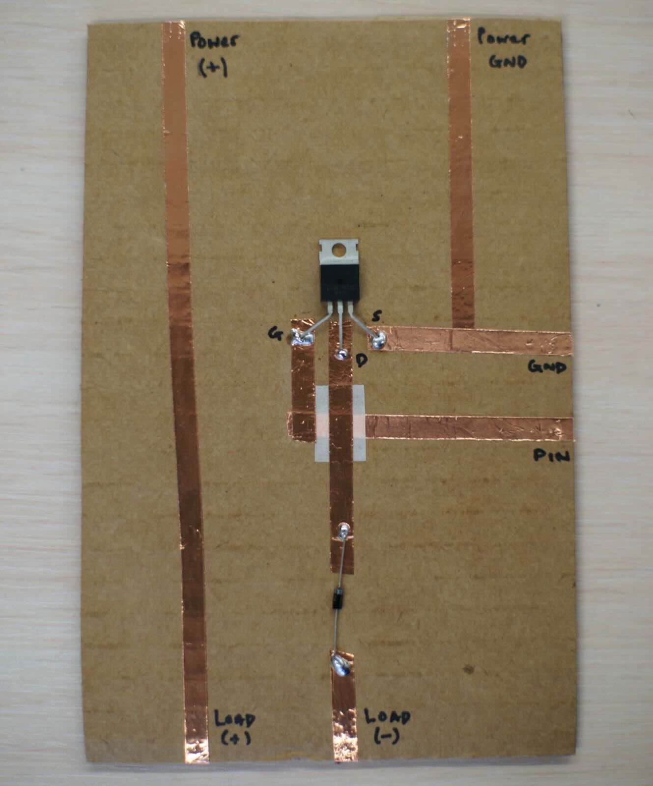 Photo by Svetlana Khachatryan
I also used a new copper wire to make a tighter stronger coil (around 150 turns). The magnet was moving from side to side. Experiment was a success!!
The code
void setup() {

  pinMode(D8, OUTPUT);// put your setup code here, to run once:
}

void loop(){
  // put your main code here, to run repeatedly:
  digitalWrite(D8, HIGH); //=> 3.3V
  delay(1000);
  digitalWrite(D8, LOW); //=> 0V
  delay (1000);
}
This was so much fun I decided to also try a faster code at Onik Babajanyan's suggestion. Oh, the small things that bring us so much excitment!
Notice how the code changes from the original "delay(1000)" to the new speed "delay(200)".
void setup() {

  pinMode(D8, OUTPUT);// put your setup code here, to run once:
}

void loop(){
  // put your main code here, to run repeatedly:
  digitalWrite(D8, HIGH); //=> 3.3V
  delay(200);
  digitalWrite(D8, LOW); //=> 0V
  delay (200);
}
Softs Speaker
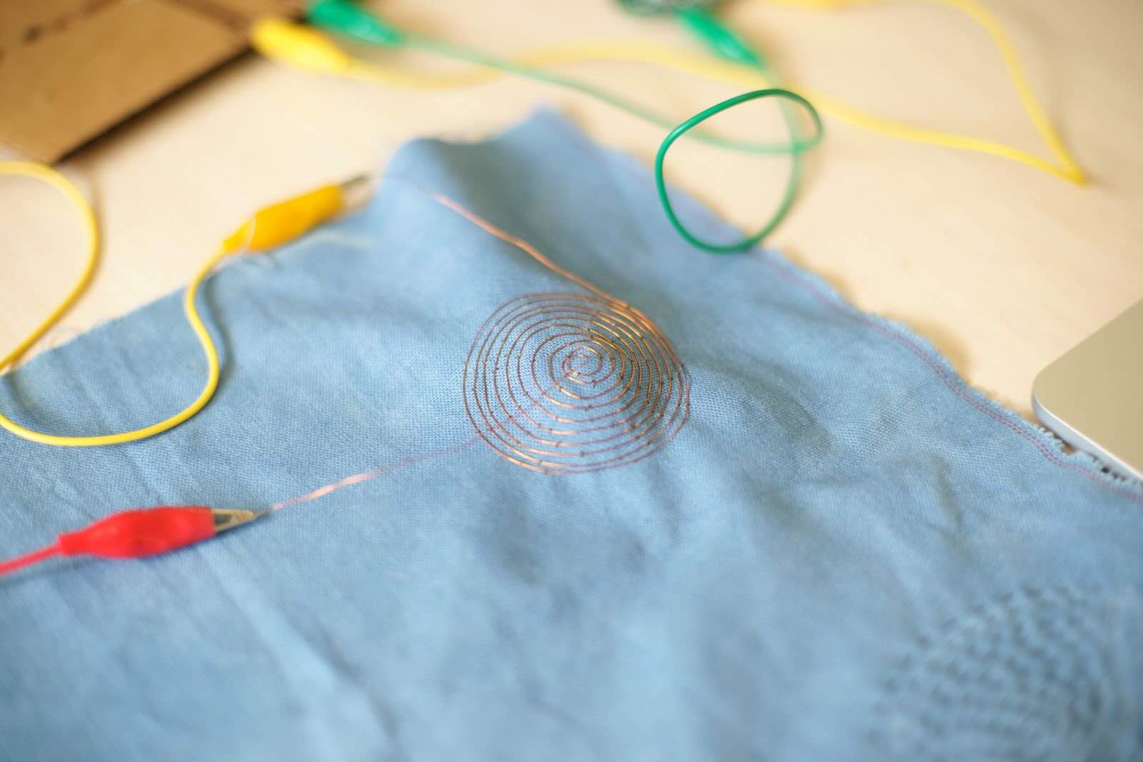 Photo by Svetlana Khachatryan
To make a speaker I used a copper wire and made a coil as neatly and tghtly as I could.
To test if it works I used the following code:
#include "pitches.h"

#define BUZZER_PIN D9

int melody[] = {
  NOTE_G4, NOTE_C4, NOTE_DS4, NOTE_F4, NOTE_G4, NOTE_C4, NOTE_DS4, NOTE_F4,
  NOTE_G4, NOTE_C4, NOTE_DS4, NOTE_F4, NOTE_G4, NOTE_C4, NOTE_DS4, NOTE_F4,
  NOTE_G4, NOTE_C4, NOTE_E4, NOTE_F4, NOTE_G4, NOTE_C4, NOTE_E4, NOTE_F4,
  NOTE_G4, NOTE_C4, NOTE_E4, NOTE_F4, NOTE_G4, NOTE_C4, NOTE_E4, NOTE_F4,
  NOTE_G4, NOTE_C4,

  NOTE_DS4, NOTE_F4, NOTE_G4, NOTE_C4, NOTE_DS4, NOTE_F4,
  NOTE_D4,
  NOTE_F4, NOTE_AS3,
  NOTE_DS4, NOTE_D4, NOTE_F4, NOTE_AS3,
  NOTE_DS4, NOTE_D4, NOTE_C4,

  NOTE_G4, NOTE_C4,

  NOTE_DS4, NOTE_F4, NOTE_G4, NOTE_C4, NOTE_DS4, NOTE_F4,
  NOTE_D4,
  NOTE_F4, NOTE_AS3,
  NOTE_DS4, NOTE_D4, NOTE_F4, NOTE_AS3,
  NOTE_DS4, NOTE_D4, NOTE_C4,
  NOTE_G4, NOTE_C4,
  NOTE_DS4, NOTE_F4, NOTE_G4,  NOTE_C4, NOTE_DS4, NOTE_F4,

  NOTE_D4,
  NOTE_F4, NOTE_AS3,
  NOTE_D4, NOTE_DS4, NOTE_D4, NOTE_AS3,
  NOTE_C4,
  NOTE_C5,
  NOTE_AS4,
  NOTE_C4,
  NOTE_G4,
  NOTE_DS4,
  NOTE_DS4, NOTE_F4,
  NOTE_G4,

  NOTE_C5,
  NOTE_AS4,
  NOTE_C4,
  NOTE_G4,
  NOTE_DS4,
  NOTE_DS4, NOTE_D4,
  NOTE_C5, NOTE_G4, NOTE_GS4, NOTE_AS4, NOTE_C5, NOTE_G4, NOTE_GS4, NOTE_AS4,
  NOTE_C5, NOTE_G4, NOTE_GS4, NOTE_AS4, NOTE_C5, NOTE_G4, NOTE_GS4, NOTE_AS4,

  NOTE_GS5, NOTE_AS5, NOTE_C6, NOTE_G5, NOTE_GS5, NOTE_AS5,
  NOTE_C6, NOTE_G5, NOTE_GS5, NOTE_AS5, NOTE_C6, NOTE_G5, NOTE_GS5, NOTE_AS5
};

int durations[] = {
  8, 8, 16, 16, 8, 8, 16, 16,
  8, 8, 16, 16, 8, 8, 16, 16,
  8, 8, 16, 16, 8, 8, 16, 16,
  8, 8, 16, 16, 8, 8, 16, 16,
  4, 4,

  16, 16, 4, 4, 16, 16,
  1,
  4, 4,
  16, 16, 4, 4,
  16, 16, 1,

  4, 4,

  16, 16, 4, 4, 16, 16,
  1,
  4, 4,
  16, 16, 4, 4,
  16, 16, 1,
  4, 4,
  16, 16, 4, 4, 16, 16,

  2,
  4, 4,
  8, 8, 8, 8,
  1,
  2,
  2,
  2,
  2,
  2,
  4, 4,
  1,

  2,
  2,
  2,
  2,
  2,
  4, 4,
  8, 8, 16, 16, 8, 8, 16, 16,
  8, 8, 16, 16, 8, 8, 16, 16,

  4, 16, 16, 8, 8, 16, 16,
  8, 16, 16, 16, 8, 8, 16, 16
};

void setup()
{
  pinMode(BUZZER_PIN, OUTPUT);
}

void loop()
{
  int size = sizeof(durations) / sizeof(int);

  for (int note = 0; note < size; note++) {
    //to calculate the note duration, take one second divided by the note type.
    //e.g. quarter note = 1000 / 4, eighth note = 1000/8, etc.
    int duration = 1000 / durations[note];
    tone(BUZZER_PIN, melody[note], duration);

//to distinguish the notes, set a minimum time between them.
//the note's duration + 30% seems to work well:
int pauseBetweenNotes = duration * 1.30;
delay(pauseBetweenNotes);

//stop the tone playing:
noTone(BUZZER_PIN);
  }
}
It was noisy at the lab but you can hear the music! And sorry for the backround noise.
For this code to work you need to download and install pitches.h to Arduino IDE.
Capacitive Sensor
To create a capacitive sensor we need an electrode connected to the microcontroller. When the electrode is charhed, it creates an electric field, and the microcontroller can detect any changes in the capacitance caused by nearby conductive objects (such as your finger). The resistor is necessary to limit current and to create measurable delay. The A0 in this case is the output pin and the A2 is the measuring pin.
In simpler terms, A0 charges and discharges the circuit through the resistor, creating a controlled voltage change. A2, on the other hand, monitors the voltage changes at the node and detects variations in charging time when capacitance increases (e.g., when a finger is nearby).
As I was using Seeed Xiao RP2040 I had to connect the sensor to one of the analog pins- A0-A3. I also used a 1 MΩ resistor to create a sensitive sensor.
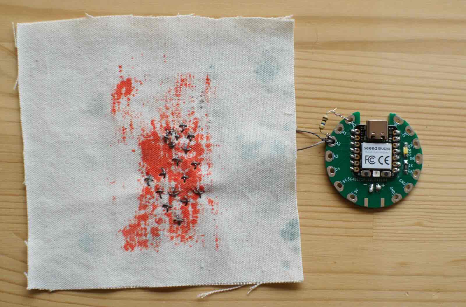
As seen in the image, I connected the conductive thread embroidery to pin A2 and connected the resistor to pin A0 and A2.
To check that the capacitive sensor works I used the following code:
const int sendPin = A0;
const int receivePin = A2;

long baseline = 0;

long readCap() {
  pinMode(receivePin, OUTPUT);
  digitalWrite(receivePin, LOW);
  delayMicroseconds(10);

  pinMode(sendPin, OUTPUT);
  digitalWrite(sendPin, HIGH);
  delayMicroseconds(10);
  digitalWrite(sendPin, LOW);

  pinMode(receivePin, INPUT);

  long count = 0;
  while (digitalRead(receivePin) == LOW && count < 5000) {
    count++;
  }

  return count;
}

void setup() {
  Serial.begin(115200);

  // calibrate baseline (no touch)
  long sum = 0;
  for (int i = 0; i < 20; i++) {
    sum += readCap();
    delay(20);
  }
  baseline = sum / 20;

  Serial.print("Baseline: ");
  Serial.println(baseline);
}

void loop() {
  long value = readCap();

  Serial.println(value);

  // invert logic based on your behavior
  if (value < baseline - 200) {
    Serial.println("TOUCHED");
  }

  delay(20);
}
Experimenting Thermo Wear
I made coil embroidery using stainless steel conductive thread. I love working with conductive thread, as I do a lot of slow stitching and this feels just like that! To understand and experiment with thermo- wear, I decided to experiment with this coil, using a W1209 thermostat module with the help of Onik Babajanyan.
W1209 Thermostat Module
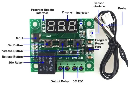
The thermostat module is a very straightforward module, that works with a 12V battery (or power supply). When you set a maximum and minimum temperature and connect the probe to the sensor interface, the relay will open when the temperature has not reached the set maximum and close once it does.
Conductive Thread
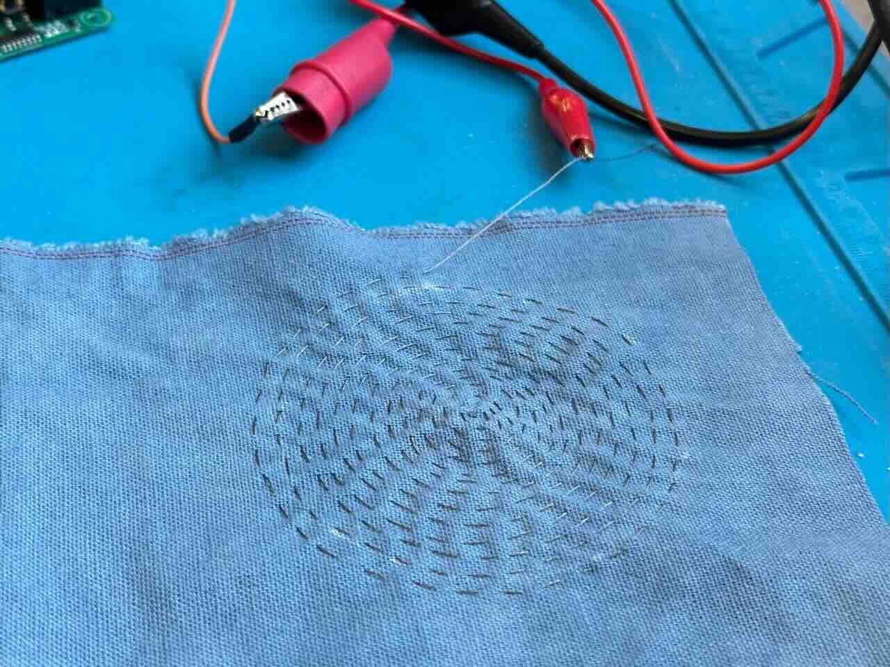 Photo by Svetlana Khachatryan
We connected one of the thread tails to the positive of the DC power supply using an alligator. We then connected the other tail to the negative of the W1209, and then from W1209 to the negative of the power supply. We then programmed for the W1209 thermostat module to allow temperatures to rise to 40C and turn off. The thermostat module comes with a temperature sensor, which we positioned on the embroidery to detect temperature changes.
Once all the connections were done and we supplied it with power, the embroidery started heating up! It was a slow rise in temperature. Something that felt controllable and safe.
Conductive Textile
Next, we experimented with the conductive textile coil. But this time we decided to really heat it up to see when the textile will melt and fall apart! Yes, our curiosity got the better of us.
At around 60C the material snapped!
Since I plan to make a heat pad that I will wear, it was interesting to see which material worked better. The conductive textile actually heated up much faster than the conductive thread. This was a very productive experiment for me.
Conductive Copper Tape
Next I did an experiment with conductive copper tape. Working with copper tape, insulated in a layer of felt would be fast and easy. I initially measured my body, then made a sketch using Adobe illustrator, to cut the copper tape with Roland.
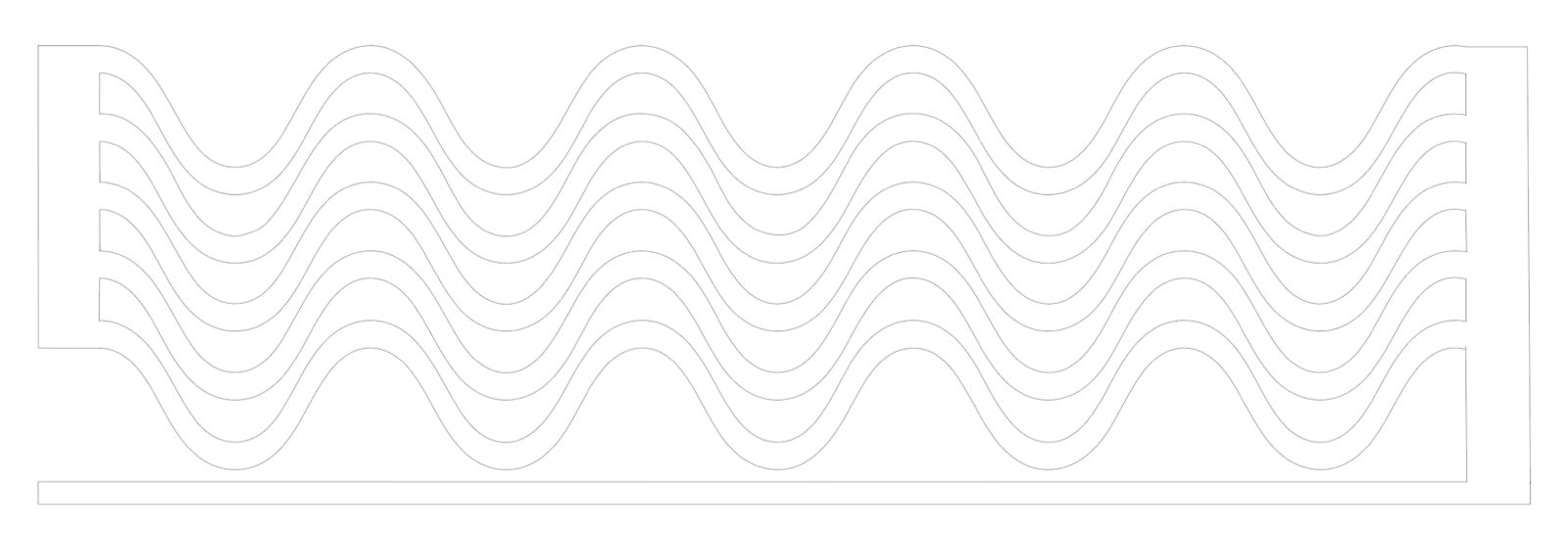
The idea was to produce even heat distribution throughout the wearable piece. The copper tape would connect to the thermostat module and work with battery. However, when I made the connection the thermostat module started blinking would not display any temperature. We then directly connected the copper tape to the DC power supply, using alligators. Copper tape does not have much resistance. I had also made a 44cm long sketch, which meant that it produced a very big amount of ampers. This experiment tought me that, if I was to use copper tape then it would have to be small and a thin singulare wave. Not the best for the product I wanted to use it for, nor for even heat distribution.
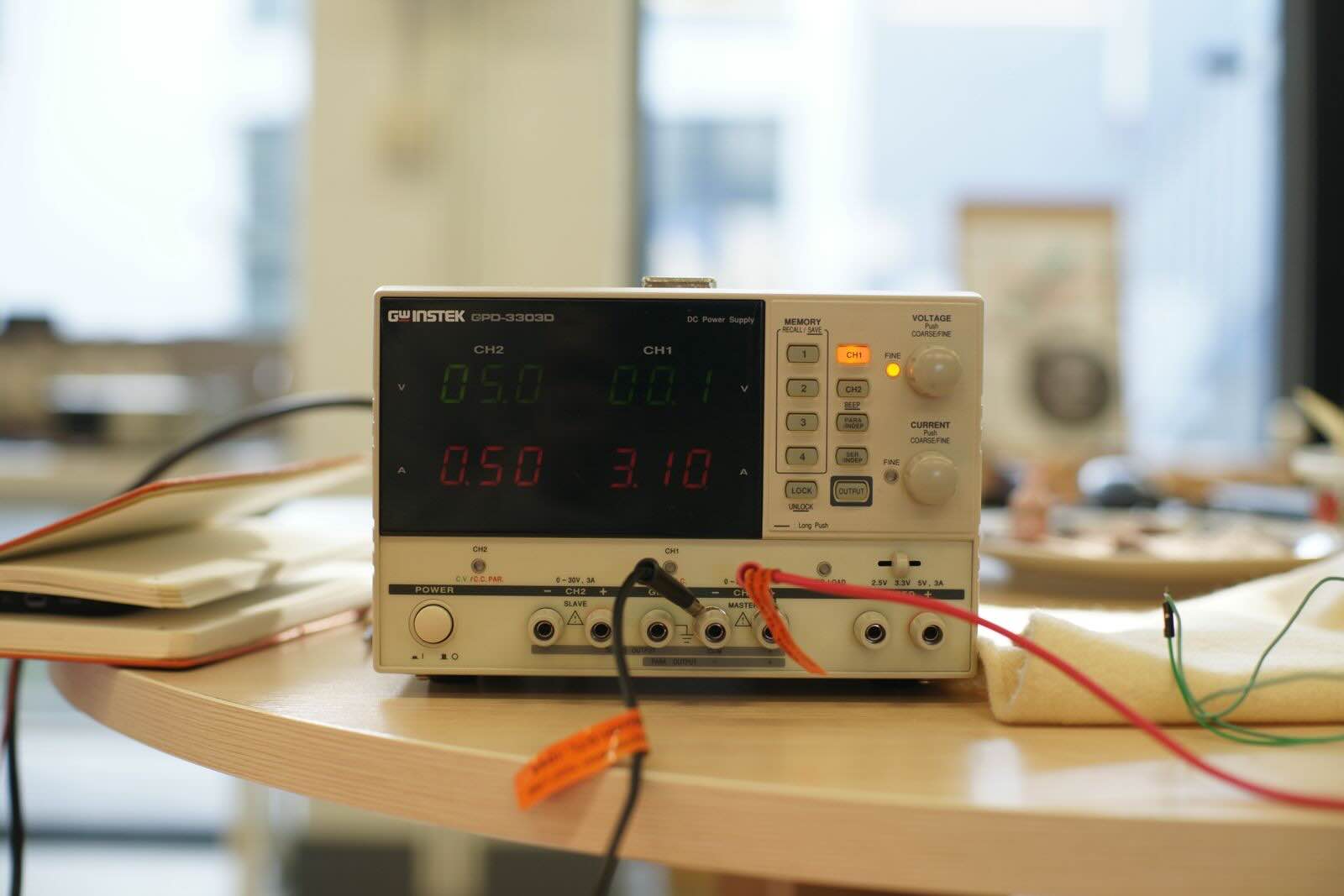 Photos by Svetlana Khachatryan
What the DC Power Supply Display is showing is that essentially due to the lack of resistance, it is creating a short circuit.
R=V/I =0.01/3.10 ≈0.003 Ω
Capacitive Sensor and Heat
Further experiments lead me to creating a small sun-like embroidery, using conductive thread on a piece of fabric with theromochromatic coating.
I initially checked the embroidery, directly with a 9V battery.
While I observed some change, it was not the effect I needed. I measured the embroidery using a multimeter, which indicated that it has 7.5 ohms.
While in theory this should have provided enough heat for the thermo coat to change colour, the 9V battery has a high internal resistance and low current capability.
I = V / R = 9 / 7.5 ≈ 1.2 A
The 9V battery cannot sustain 1.2 A.
So, I changed the battery to a 3.7 V LiPo battery.
Which Instantly worked!!
I then connected the embroidery to the circuit I had created and used the following code:
const int sendPin = A0;
const int receivePin = A2;
const int outputPin = D8;

long baseline = 0;

long readCap() {
  pinMode(receivePin, OUTPUT);
  digitalWrite(receivePin, LOW);
  delayMicroseconds(10);

  pinMode(sendPin, OUTPUT);
  digitalWrite(sendPin, HIGH);
  delayMicroseconds(10);
  digitalWrite(sendPin, LOW);

  pinMode(receivePin, INPUT);

  long count = 0;
  while (digitalRead(receivePin) == LOW && count < 5000) {
    count++;
  }

  return count;
}

void setup() {
  Serial.begin(115200);
  pinMode(outputPin, OUTPUT);

  // calibrate baseline (no touch)
  long sum = 0;
  for (int i = 0; i < 20; i++) {
    sum += readCap();
    delay(20);
  }
  baseline = sum / 20;

  Serial.print("Baseline: ");
  Serial.println(baseline);
}

void loop() {
  long value = readCap();

  Serial.println(value);

  // TOUCH DETECTION (same logic you confirmed works)
  if (value < baseline - 200) {
    digitalWrite(outputPin, HIGH);  // ON
    Serial.println("TOUCH → D8 HIGH");
  }
  else {
    digitalWrite(outputPin, LOW);   // OFF
  }

  delay(20);
}
This design can be playfully added to so many garments. I imagine the capacitive sensor to be a brooche for example, and the embroidery to sit on the sleeve of a shirt.
Capacitive Sensor and Soft Speaker
One last fun experiment I decided to do was to connect the capacitive sensor to the speaker. Initially I connected it to the 9V battery which worked fine, but since the sound coming from the speaker was not loud enough to be properly recorded (especially with all the background noise in the lab) we decided to have a little bit of fun and experimented with the DC power supply.
I used the following code:
#include "pitches.h"

#define BUZZER_PIN D8

const int sendPin = A0;
const int receivePin = A2;

long baseline = 0;
bool isPlaying = false;

// ---------------- CAPACITIVE SENSOR ----------------
long readCap() {
  pinMode(receivePin, OUTPUT);
  digitalWrite(receivePin, LOW);
  delayMicroseconds(10);

  pinMode(sendPin, OUTPUT);
  digitalWrite(sendPin, HIGH);
  delayMicroseconds(10);
  digitalWrite(sendPin, LOW);

  pinMode(receivePin, INPUT);

  long count = 0;
  while (digitalRead(receivePin) == LOW && count < 5000) {
    count++;
  }

  return count;
}

// ---------------- MELODY ----------------
int melody[] = {
  NOTE_G4, NOTE_C4, NOTE_DS4, NOTE_F4, NOTE_G4, NOTE_C4, NOTE_DS4, NOTE_F4,
  NOTE_G4, NOTE_C4, NOTE_DS4, NOTE_F4, NOTE_G4, NOTE_C4, NOTE_DS4, NOTE_F4,
  NOTE_G4, NOTE_C4, NOTE_E4, NOTE_F4, NOTE_G4, NOTE_C4, NOTE_E4, NOTE_F4,
  NOTE_G4, NOTE_C4, NOTE_E4, NOTE_F4, NOTE_G4, NOTE_C4, NOTE_E4, NOTE_F4,
  NOTE_G4, NOTE_C4
};

int durations[] = {
  8, 8, 16, 16, 8, 8, 16, 16,
  8, 8, 16, 16, 8, 8, 16, 16,
  8, 8, 16, 16, 8, 8, 16, 16,
  8, 8, 16, 16, 8, 8, 16, 16,
  4, 4
};

// ---------------- PLAY FUNCTION ----------------
void playMelody() {
  int size = sizeof(durations) / sizeof(int);

  for (int note = 0; note < size; note++) {
    int duration = 1000 / durations[note];

    tone(BUZZER_PIN, melody[note], duration);

    int pauseBetweenNotes = duration * 1.30;
    delay(pauseBetweenNotes);

    noTone(BUZZER_PIN);
  }
}

// ---------------- SETUP ----------------
void setup() {
  Serial.begin(115200);
  pinMode(BUZZER_PIN, OUTPUT);

  // baseline calibration
  long sum = 0;
  for (int i = 0; i < 20; i++) {
    sum += readCap();
    delay(20);
  }
  baseline = sum / 20;

  Serial.print("Baseline: ");
  Serial.println(baseline);
}

// ---------------- LOOP ----------------
void loop() {
  long value = readCap();
  Serial.println(value);

  bool touched = (value < baseline - 200);

  if (touched && !isPlaying) {
    isPlaying = true;
    Serial.println("TOUCH → PLAY MUSIC");

    playMelody();

    isPlaying = false;
  }

  delay(20);
}
I was having too much fun with the magnets and the speaker
UNMUTE
Also, here is how sensitive the capacitive sensors actually are.
UNMUTE