E-textiles
References, Research & Inspiration
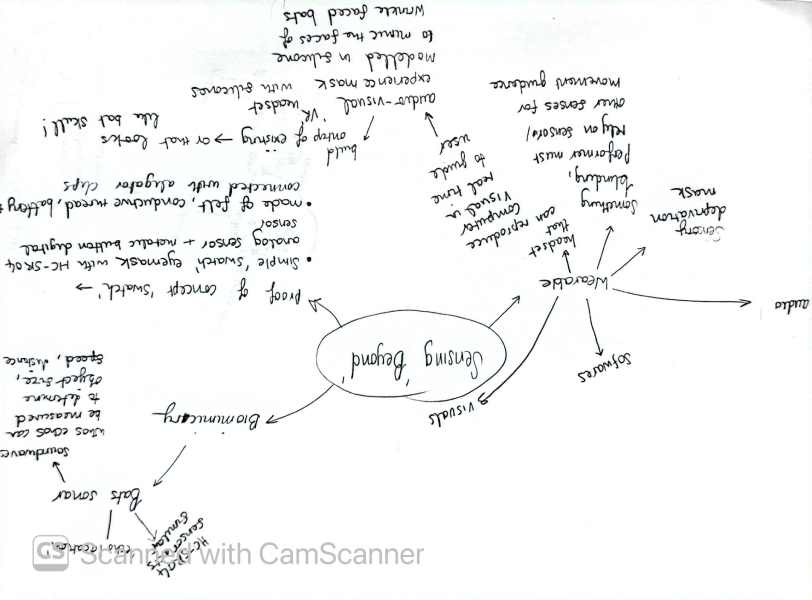 Sensing beyond Mindmap, created by gh0re.grl 2026
Project References
A Fabric that Remembers - Laura Devendorf / The Musical Jacket - Maggie Orth / PolySense / Stymphalian Birds: Sensing Beyond the Human Body with Feathers
My project was inspired primarily by two projects: A Fabric that Remembers by Laura Devendorf and Stymphalian Birds: Sensing Beyond the Human Body with Feathers by Audrey Briot. I was initially intrigued by Devendorf’s idea of translating sensor data into audiovisual display, and utilising your sensor for data collection and further output. Creatively, Stymphalian Birds bought my concept to a new level. I was inspired by Briot’s concept of ‘sensing beyond’ and utilising biomimicry as a tool for enhancing human sensory experience. I had the idea to also simulate biomimicry, but for almost the opposite purpose.
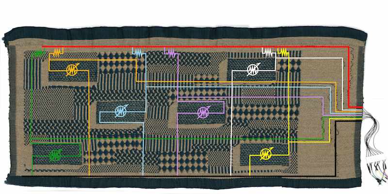 A Fabric that Remembers - Laura Devendorf
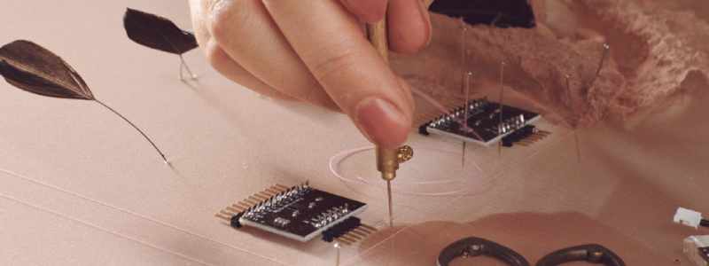 Stymphalian Birds: Sensing Beyond the Human Body with Feathers
The first animal with extreme senses that came to my mind was Bats. Their sonar/ ‘echo location’ is a fascinating tool they use to map objects in the dark using high pitch sound waves and refracted echo. This made me think of the HC-SRO4 sensor I had from the Parasites&Robotics workshop I attended last year by Salvador Marino. In the workshop, he explained that this sensor was working on the same principles of echolocation as bats to detect objects. It also made me think of sensory deprivation (as bats use echolocation in darkness), a parallel concept to Briot’s sensory enhancement.
Sensory deprivation is practiced by humans in many forms (via masks, vacuum beds, live burials), as a form of ritual, meditation, fetish etc. I began reimagining a deprivation mask with the sensor installed, allowing a human-hybrid echolocation experience. If the data from the sensor was filtered through programmes like pure data, it could create an audio landscape that could inform the wearer of their proximity to objects, guiding their responses, just like a bat.

Sensory Deprivation Mask from @polarred22 on Ebay

Wrinkle Faced Bat by Bruce D. Taubert
I will develop the mask in the wearables week, but for my first step I will create a proof of concept swatch to sample the tech for this more advanced project. I will use a metallic zipper placed by the eyes for my digital sensor, and place the HC-SRO4 sensor by the mouth, to mimic the unconventional shapes of a fetish mask.
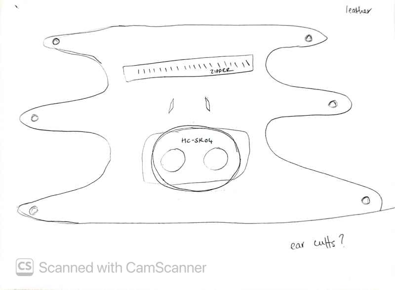 Wearable Concept Sketch, created by gh0re.grl, 2026
Tools
Process and Workflow
BASIC USE OF ARDUINO AND BREADBOARD
First we made an experiment with an LED, an Arduino UNO board and a breadboard.
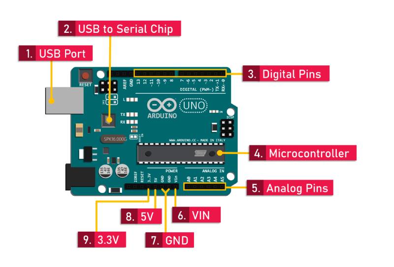
To use Arduino, you must connect the microcontroller to your laptop via the USB port and open the software (Arduino IDE). You then must ‘select board’ and make sure you are connected. Below is an explanation from Beekjock about the first two pieces of code available in a new Arduino IDE sketch:
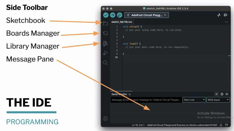 Slide from Lisa Stark's tutorial, Fabricademy 2026
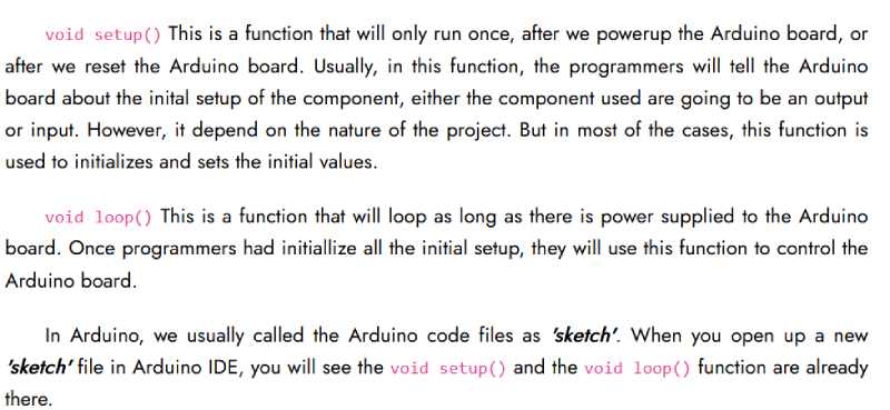
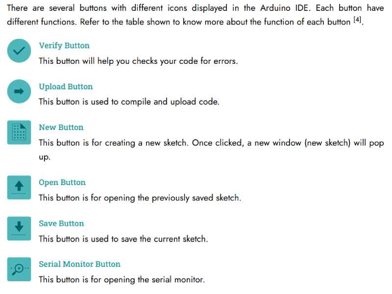
Arduino Tutorial- Beejok, 2023
However for our first experiment we used just the board and a breadboard to create a simple LED circuit. Here are the ports used/worth mentioning:
Digital Ports: Plug in for Digital sensors Analog Ports: Plug in for Analog sensors Voltage: Different plug ins with different voltages Pin 13: Has a built in resistor GND: Ground Pin
For all circuits, we must have one wire in voltage, one wire in ground, both connected to the breadboard as beginning and end points of our circuit. We tested first a basic circuit with a resistor and an LED.
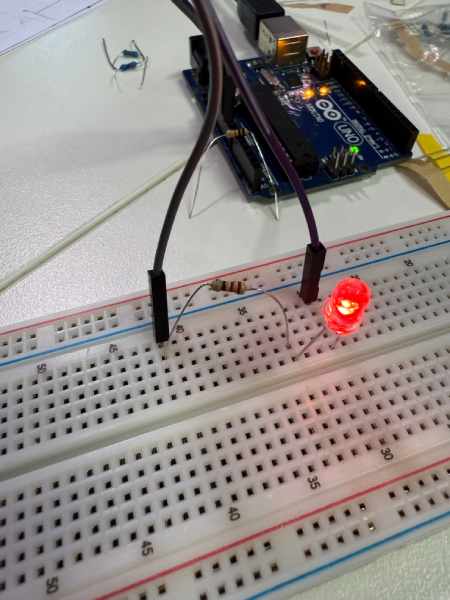
Simple LED Circuit. Documented by gh0re.grl, 2026.
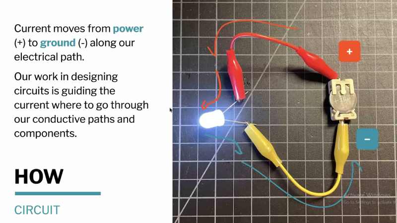
Slide from Liza Stark's presentation at Fabricademy, 2026
Although here our resistor is after the LED, in hindsight it would make more sense to put the resistor first to filter the current through the resistance before reaching the LED. You can decide what resistor to use by assessing the voltage of the battery you are using and what current is required by your desired device. You can find out the value of a resisor or the voltage of a power source using a multimeter.
HOW TO USE A MULTIMETER
A multimeter can be used to measure Voltage, Current, Resistance and continuity. You need to plug the black wire into the COM port on the right, and the red wire into the VΩZ port next to it. Below I have labelled the different functions, and have documented the process for a continuity test, which I used later this week.
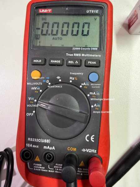
Multimeter in Biolab Lisboa. Labelled by gh0re.grl, 2026.
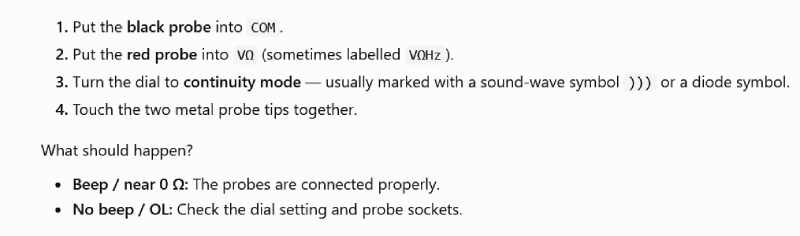
Screenshot from ChatGPT on how to do a Continuity Test. Taken by gh0re.grl, 2026
HOW TO USE A BREADBOARD
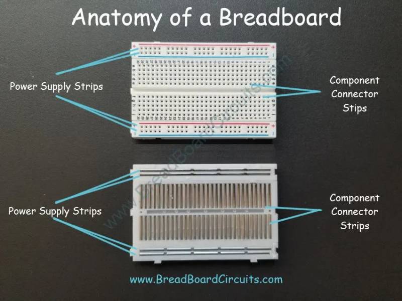
A breadboard is used to extend the number of connections providing component connector strips in a grid format. As you can see there are a series of connector strips running vertically with a break in the middle. Each line is singularly connected, so connections are not initially made horizontally (must be connected through a conductive material: wire, resistor etc).
Adding a Momentary Button:
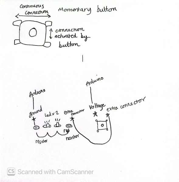 Momentary Button Circuit Sketch. Gh0re.grl, 2026
We experimented with a momentary button as an example of a digital sensor. This sensor works by having a continuous connection between the two lines vertically, and a connection between the horizontal lines that can be activated through pressure (button push). To create a circuit using this sensor, you must use the voltage wire connected to the Arduino, and a 3rd extra wire. The voltage connects to the first side, and the extra wire connects to the next side horizontally, so that the connection between the wires is only activated by a pressure. The other side of the 3rd extra wire must be connected to the pathway/beginning of the LED circuit, connecting the voltage to the rest of the circuit.
Momentary button test. Performed by gh0re.grl, Biolab Lisboa, 2026
Analog Sensor
I had originally believed my project included both an analog and digital sensor, but actually it includes analog and digital data read by two digital sensors. There are three different components that can be utilised to create an analog sensor:
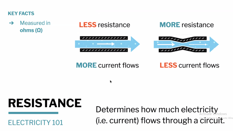
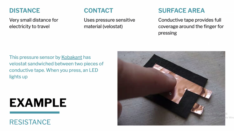 Slides from Liza Stark's presentation at Fabricademy, 2026
I wanted to create a small example using contact. When pressed, the resistance decreases allowing more electricity to flow through the circuit. This is in turn used to track pressure/weight on an interface or object.
I followed the design shown below:
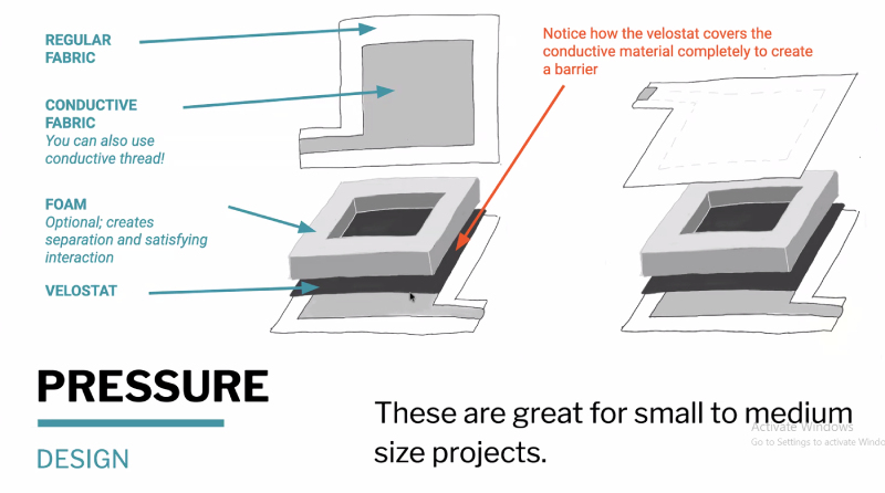
Slide from Liza Stark's presentation at Fabricademy, 2026
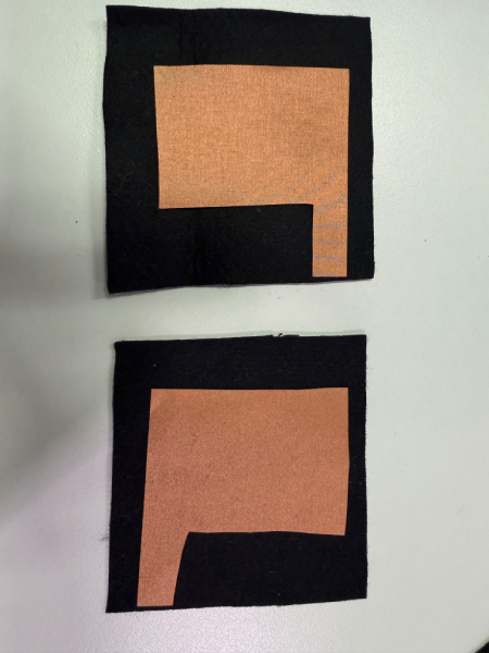 Step 1: Cut regular and conductive fabric. |
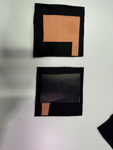 Step 2: Add velostat square around the same size as conductive fabric. |
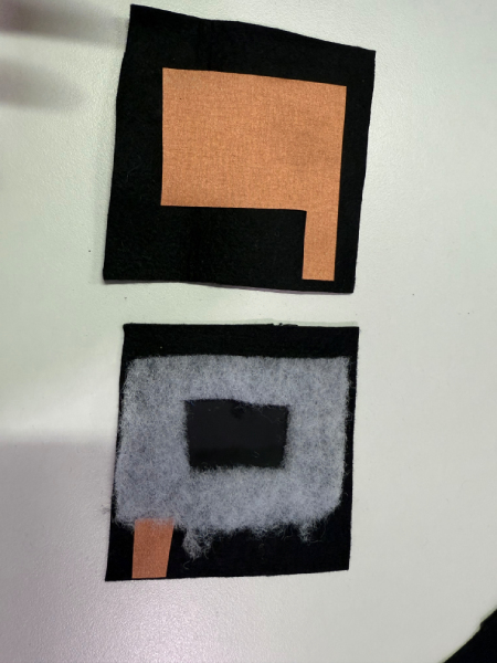 Step 3: add square of foam with central hole that will allow conductive materials to touch when pressed. |
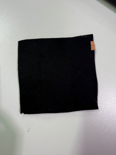 Step 4: Apply top layer and sew together. Make sure all elements are secure and layered correctly. |
Analog sensor created and documented by gh0re.grl, 2026
For this experiment, I used the sensor to control the LED. Using the same circuit we had practiced previously, I added the analog sensor and used pressure to manipulate the resistence and therfore create variation in the LED brightness.
COLLECTING DATA FROM SENSORS IN ARDUINO
We ran some tests on Carlotta's swatches to test collecting Data from her digital and analog sensors. Her pressure pad worked as both a digital and an analog sensor, connecting the circuit when the swatch was ‘shut’ to put the conductive materials together, whilst sensing pressure when pushed. Using this swatch, Guilherme showed me how to collect data from the sensors:
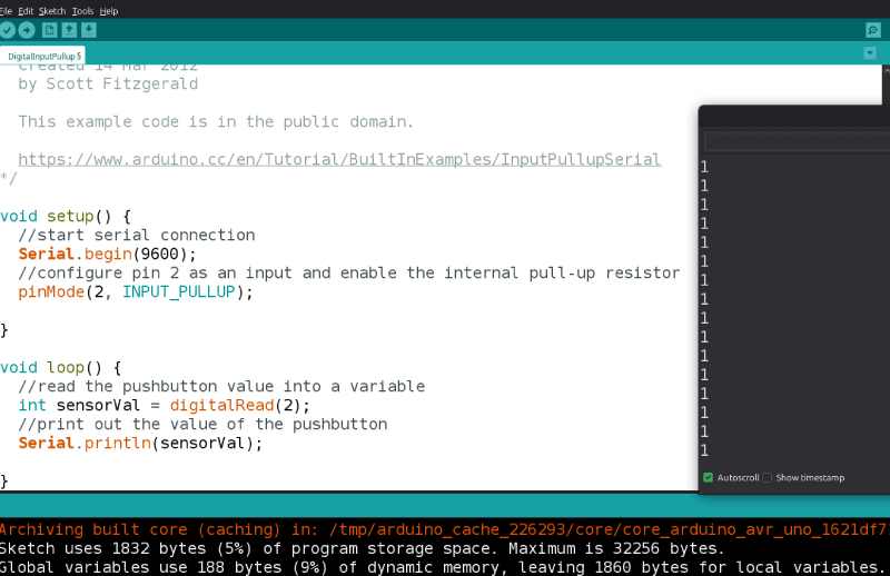
Screenshot from Arduino IDE, showing how to collect data from sensors. Documented by gh0re.grl, 2026
Serial.begin() is a command used in Arduino programming to start communication between your Arduino and your computer. 9600: sets the communication speed, called the baud rate. It must match the speed selected on your computer's Serial Monitor. pinMode - Selected pin to follow given commands (connect wiring here) INPUT: The pin reads a signal from something connected to it. E.g Reading a button INPUT_PULLUP: The pin reads a signal and uses a built-in resistor to keep the signal HIGH when nothing pulls it LOW. e.g Reading a button with simpler wiring.
Sensor val: sensor value aka what the Arduino should read Digital read: A digital sensor! Serial.print(): Send a message. Serial.println(): Send a message and move to the next line.
This setup would also work for an analog sensor, and the code can be copied with a simple replacement of digitalRead with analogRead.
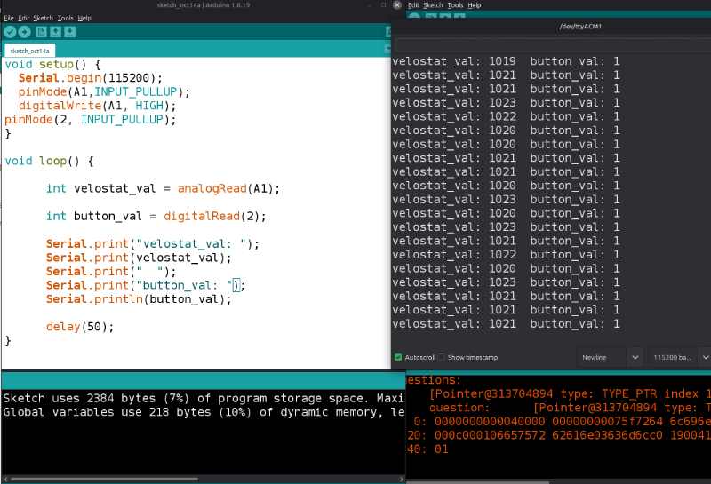 Screenshot from Arduino IDE, showing how to collect data from two sensors and display it seperatley in the serial monitor. Documented by gh0re.grl, 2026
Here we see an example of running both simultaneously, and a readable way of data collection. You can see how you must change the ‘serial print’ to produce a organised / user-friendly data chart, and how to set up both sensors simultaneously. This is the method I will use for my swatch.
WIRING SKETCHES:
I decided to create my swatch in felt, as I will probably create my mask in leather and line it with felt, which will also have the tech installed. My first sketch of the proposed circuit was:
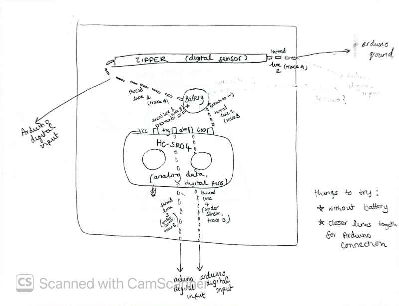 Circuit sketch prototype, gh0re.grl 2026.
I first envisioned the circuit with a battery and also connections to the Arduino Uno. I realised after that this didn’t make sense as the Arduino can easily act as a power source, and it will only be necessary for the mask to use battery / Arduino Model XIAO-ESP32-C3 (Wifi Arduino). It was overcomplicated and I couldn’t quite work out if it would work this way or not, so I redrew using clearer, simpler pathways and linking everything back to the Arduino Board.
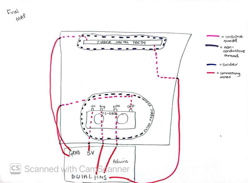 Circuit sketch: final map. Gh0re.grl 2026.
I then created this sketch, but realised both circuits were separate so it would be better to propose an option where the zipper could function fully as a switch. This was my proposal, but Guillherme pointed out to me that here the sensor was always connected to the voltage here too through the digital pin.
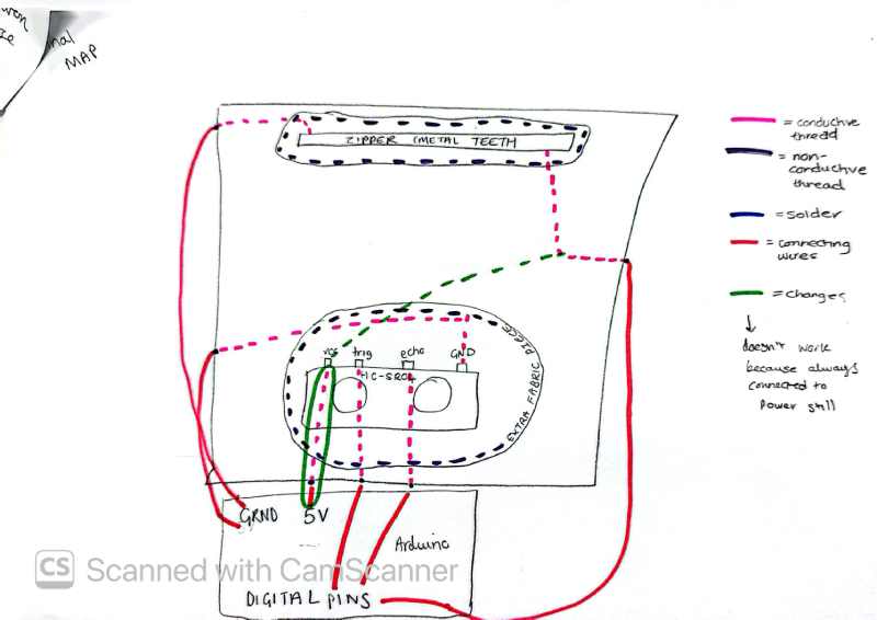 Circuit sketch prototype, gh0re.grl 2026.
He also informed me that it is possible to programme the Arduino to only activate the sensor when the zipper connection is activated, making my first plan viable for this sample.
CREATING THE SWATCH:
First I stitched all non-conductive elements, creating the foundations of the swatch. I then added conductive thread to the zipper. I realised that for this experiment, conductive thread was not necessary for the sensor, only 4 x male to female wires.
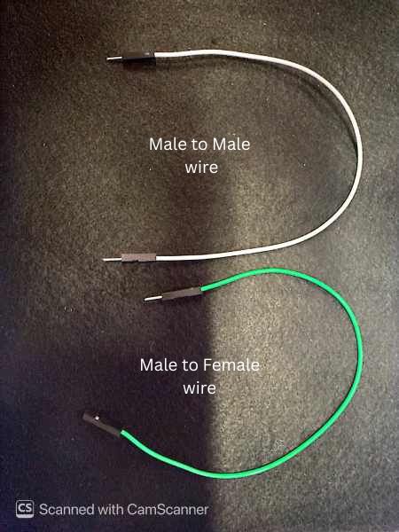 male and female wires. Displayed and labelled by gh0re.grl, 2026
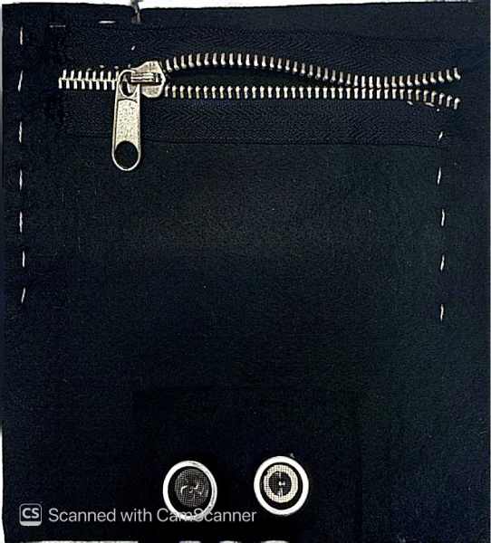 Prototype e-textile swatch. Produced by gh0re.grl, Biolab Lisboa, 2026.
I struggled to get the conductive thread close enough to the zipper teeth. I tried attaching them to the teeth, but it jammed the zipper, so I then stitched the path very close to the teeth and hoped for the best!
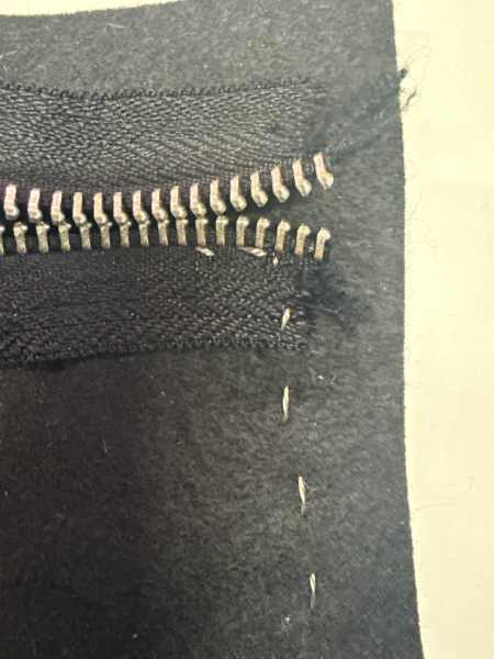 Initial conductive thread stitch technique applied by gh0re.grl, 2026
I did a continuity test, and realised that there was a problem with my stitching technique. Returning to Carolina’s swatch as reference, I realised my stitches were spaced too far apart, and that the zipper could not be a trusted conductor over a long space.
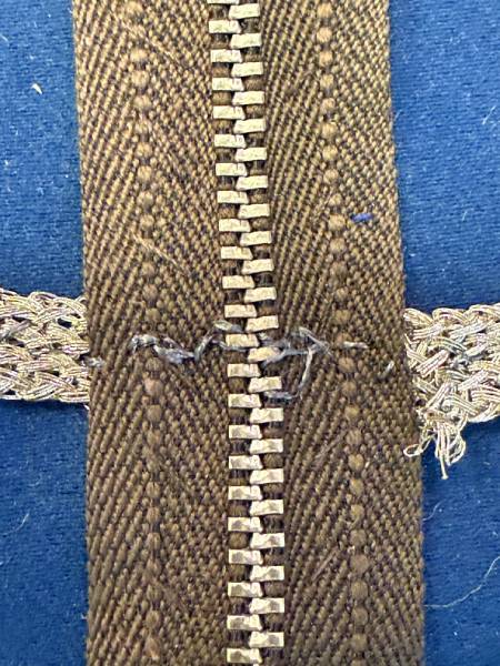
Carolina Delgado’s Zipper Switch Swatch. Documented by gh0re.grl at Biolab Lisboa, 2026
I adjusted my stitches and tested the connection again. I added two new threads, connected to the old threads by safety pins, that lead the connective threads to the centre of the zipper, letting them overlap in the teeth and connecting the zipper from both sides.
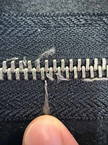
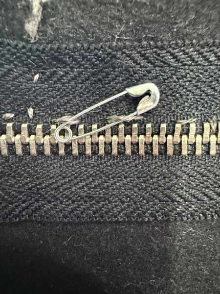
Final stitch technique applied to my E-textiles swatch. Produced and documented by gh0re.grl, 2026 ...
Results
Testing Digital and Analog sensor function: Results shown in Serial Plotter. Documented by gh0re.grl at Biolab Lisboa, 2026
Demonstration of using Zipper to control data collection. Documented by Gh0re.grl at Biolab Lisboa, 2026.
5.1 Code
Arduino Code as Text:
Arduino Code as Text
const int trigPin = 9; const int echoPin = 10; const int zipPin = 12; int zipState; float duration, distance; void setup() {Serial.begin(9600); // sonar sensor pinMode(trigPin, OUTPUT); pinMode(echoPin, INPUT); //zip pinMode(zipPin, INPUT_PULLUP);} int temp; void loop() { if (zipsensor() == 0) {callSensor();}} void callSensor() {sonarsensor(); if (zipState == 1) temp = 350; else temp = 150; Serial.print(0); Serial.print(" "); Serial.print(400);Serial.print(" "); Serial.print(temp); Serial.print(" "); Serial.print(distance); Serial.println();} int zipsensor() { zipState = digitalRea(zipPin); return zipState; delay(100);} void sonarsensor() {digitalWrite(trigPin, LOW); delayMicroseconds(2); digitalWrite(trigPin, HIGH);delayMicroseconds(10); digitalWrite(trigPin, LOW); duration = pulseIn(echoPin, HIGH); distance = (duration * .0343) / 2; delay(100);}
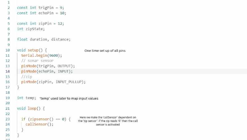
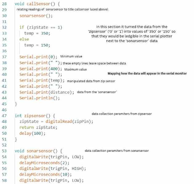
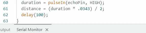
My final Arduino code: explained. Notes by gh0re.grl