Soft robotics
Objective
weekly assignment
Check out the weekly assignment here or login to your NuEval progress and evaluation page.
get inspired!
Check out and research alumni pages to betetr understand how to document and get inspired
-
materials comparison - Julija Karas - FabLab Bcn
-
Artistic intervention - Riley Cox - TextileLab Amsterdam
Add your fav alumni's pages as references
References, research & inspiration
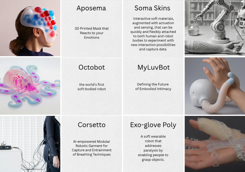
I was inspired this week by the idea of interactive soft materials. Projects like Soma Skins, Corsetto and Exo-glove Poly utilise soft robotics as a way to rethink the possibilities of human and robotic interaction in a practical, embodied sense. I also enjoyed projects like Aposema for their creative application of soft materials as sensors. It got me thinking about how we interact with outside forms as tools of benefit to our bodies. About intimacy and interaction. I went with an Octopus tentacle as my starter design, as the tentacle has been a common theme in outsider intimacy.
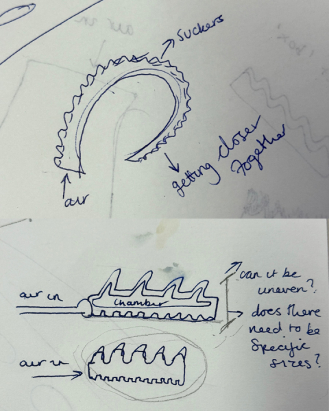
Concept sketch / Simplified design concept. Gh0re.grl, 2026
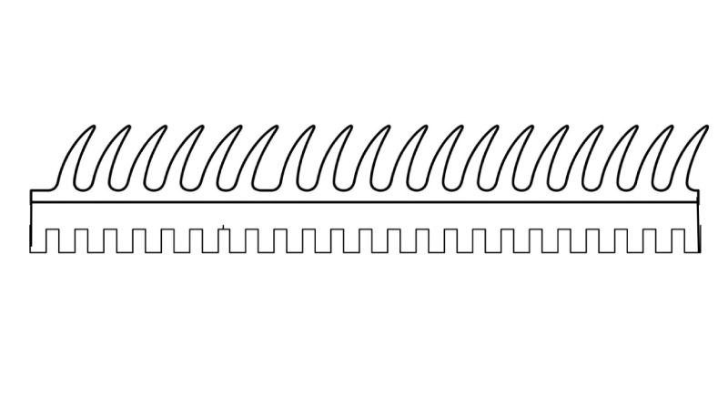
Digital illustration of concept. Gh0re.grl, 2026
Tools
Tutorials
Research
Process and workflow
What is a Soft Actuator?
A soft actuator is a deformable, compliant component made of flexible materials—such as silicone, rubber, fabric, or hydrogels—that converts an energy source (like air pressure, liquid, or electricity) into controlled mechanical motion. - Soft Robotic Systems and Actuation Technologies, Nature Index
Examples of Soft Actuators available for us to explore at Biolab Lisboa, 2026
Actuator 01: Baking Paper and Thermo Vinyl
 |
 |
 |
 |
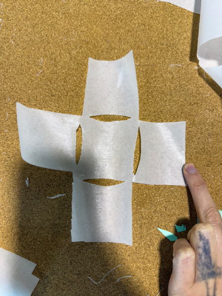
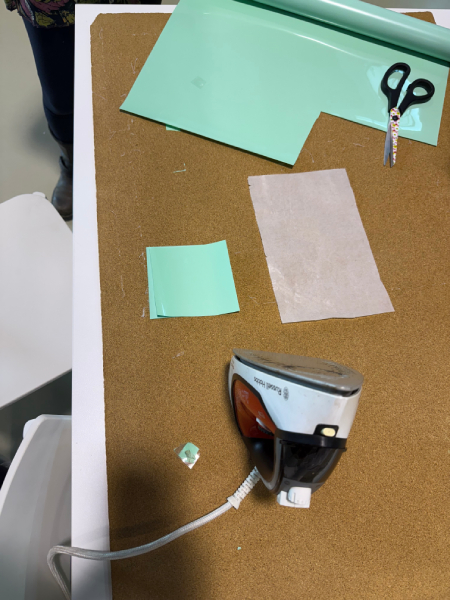
Step 1: Create a design in baking paper and cut out. I created a simple design with 6 small prongs. All designs must have an entry point for pump nozzle.
Step 2: Cut vinyl in square shape leaving border of around 1cm around baking paper.
Step 3: Cut the exact shape again. Make sure to remember that the shiny side is on the outside, so mirror the shape accordingly so they fit together.
Step 4: Centre baking paper in the vinyl square. Place a second vinyl on top to ‘sandwich’ it. Shiny side of vinyl facing outwards on both sides.
Step 5: make sure that there is a piece of baking paper outside the vinyl, leaving a pocket/entrance for the pump nozzle.
Step 6: Iron vinyl on medium heat. Protect material with fabric / another sheet of baking paper and iron slowly.
Step 7: Peel protective ‘shiny’ material from both sides of the vinyl. Actuator is ready for use!
Lessons learnt: not to overfill with air. I put the pump on full power very quickly and after my second test my actuator burst.
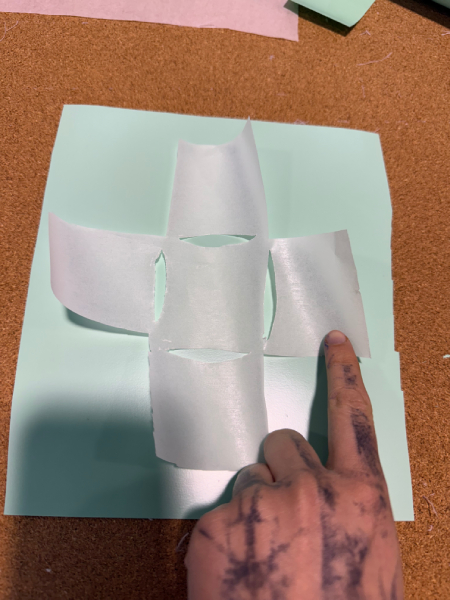
Lessons learnt: I was experimenting with the shape and hoping that the fingers may move or twist the shape, but no movement was made with this shape.
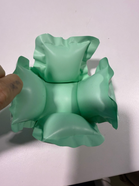
Lessons learnt: I then used a box cutter to create small cuts that would allow movement within the model. Creating this movement required thinking carefully about how air pressure affects the structure. By leaving certain internal sections sealed, the surrounding air pockets expand and cause the shape to bend inward. Similarly, making slanted cuts encourages the material to fold forward over the sealed sections, as these static areas resist expansion while the surrounding air pockets continue to inflate.

How-to use footnotes for fabrication files
Fabrication files are a necessary element for evaluation. You can add the fabrication files at the bottom of the page and link them as a footnote. This was your work stays organised and files will be all together at the bottom of the page. Footnotes are created using 1 (without spaces, as shown in Step 1 & 2, and referenced as you see at the bottom of this page) You can reference the fabrication files to multiple places on your page.
4.1 Step 1
This model 3 was obtained by.. Lorem ipsum dolor sit amet, consectetur adipiscing elit, sed do eiusmod tempor incididunt ut labore et dolore magna aliqua.
4.2 Step 2
The laser cut nesting 2 was created using.. Lorem ipsum dolor sit amet, consectetur adipiscing elit, sed do eiusmod tempor incididunt ut labore et dolore magna aliqua.
4.3 Step 3
...
5. Results
Results & documentation
- Don’t forget to document the outcome including:
- Final result
- Photos from different stages
- Videos of movement or interaction, show how a material moves, something was assembled or the interactive
- Include measurements or a reference object to give a sense of size
- Describe the (material) properties or what you made
- Comparison between attempts, if you did multiple experiments or generated multiple files before fabricating / deploying. You can use a table as shown in week 4
5.1 Code
Use the three backticks to separate code.
// the setup function runs once when you press reset or power the board
void setup() {
  // initialize digital pin LED_BUILTIN as an output.
  pinMode(LED_BUILTIN, OUTPUT);
}

// the loop function runs over and over again forever
void loop() {
  digitalWrite(LED_BUILTIN, HIGH);   // turn the LED on (HIGH is the voltage level)
  delay(1000);                       // wait for a second
  digitalWrite(LED_BUILTIN, LOW);    // turn the LED off by making the voltage LOW
  delay(1000);                       // wait for a second
}

// the setup function runs once when you press reset or power the board
void setup() {
  // initialize digital pin LED_BUILTIN as an output.
  pinMode(LED_BUILTIN, OUTPUT);
}

// the loop function runs over and over again forever
void loop() {
  digitalWrite(LED_BUILTIN, HIGH);   // turn the LED on (HIGH is the voltage level)
  delay(1000);                       // wait for a second
  digitalWrite(LED_BUILTIN, LOW);    // turn the LED off by making the voltage LOW
  delay(1000);                       // wait for a second
}
6. Weekly reflection & critical thinking
- What did I learn? What did I personally find interesting or surprised me?
- What would I do differently? If something "failed" do I know how else to tackle it now?"
- How does this connect to my final project or my learning trajectory?
- What are implications and possible applications, think also from the ethical or environmental aspect, how it could connect to your practice and project?
NuEval — final step
Go to NuEval and fill in the checklist, when not complete notify your instructor.
7. Fabrication files & References
-
File: Laser cut matrix ↩
-
Reference: Author; Title; Source; year ↩