Computational Couture
1. Project Objective & Conceptual Design - From Typhoon to Textile
CHAMPI 薔琵 — Wearing the Storm
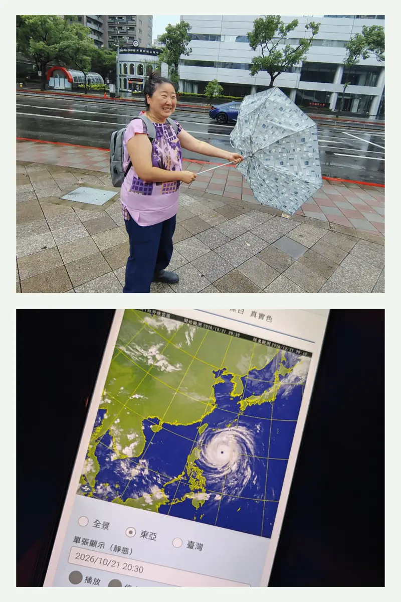
Inspired by the typhoon that swept through Taiwan during my visit this week, I wanted to explore how computational couture could translate the forces of nature into wearable structures.
Rather than simply representing a typhoon visually, my objective is to transform the movement of wind, the geometry of a vortex, and the concept of resilience into a functional, flexible, 3D-printed textile. The resulting concept, CHAMPI — Wearing the Storm, will explore the relationship between rigidity and flexibility, technology and craftsmanship, and the ability of structures to adapt to external forces. My goal is to develop a workflow from digitally generated fashion concept toward a physically printable wearable garment.
Cultural Design Language: Although for this homework specifically I won't be producing full garment, but I want to start thinking ahead and develop the concepts integrating the silhouette of a traditional Chinese qipao, including its mandarin collar, frog-button closures, and side slit, with contemporary computational fabrication.
Concept 1
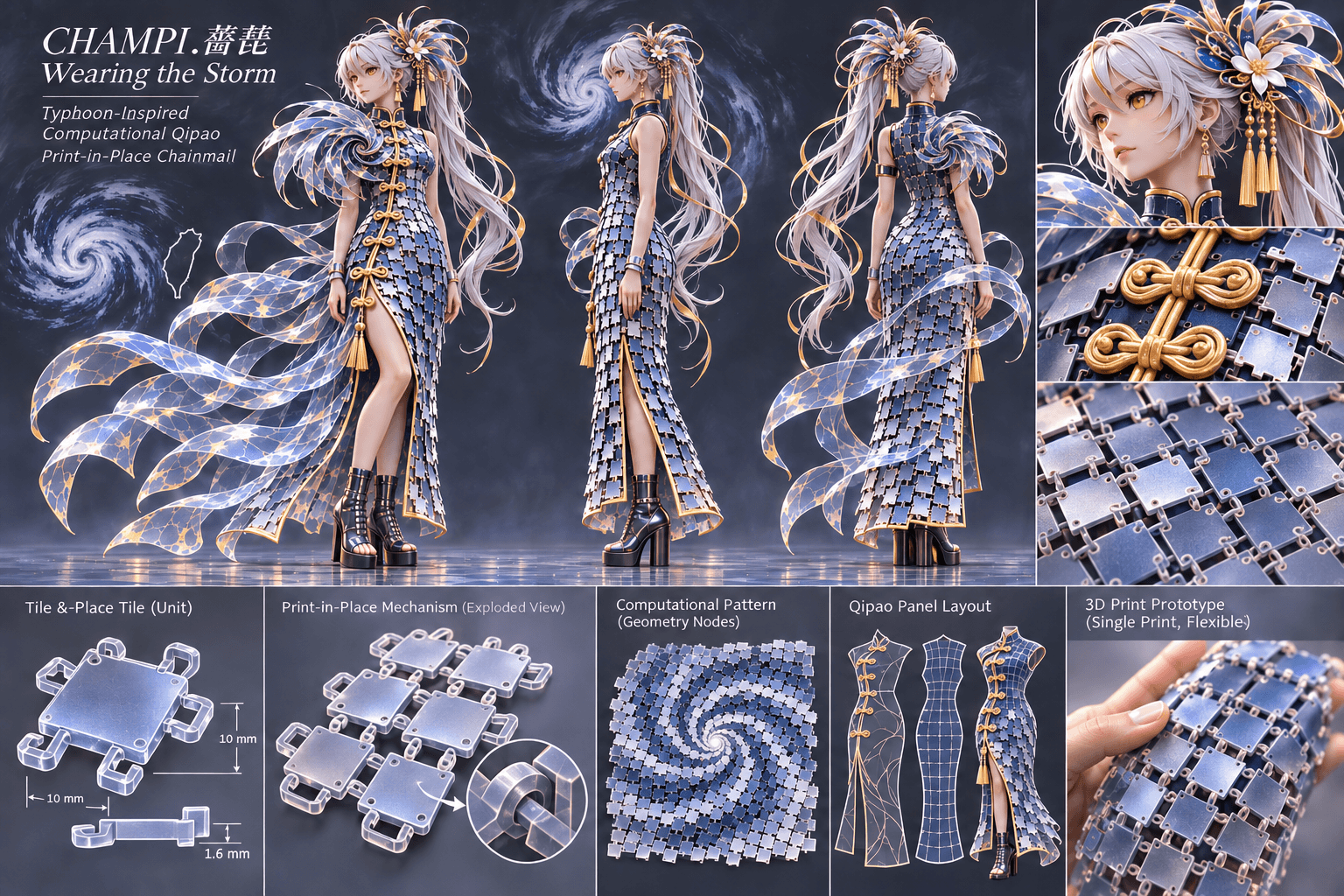
The design explores Print in Place Modular Tiles:
- Computational Geometry: Using Blender Geometry Nodes to generate a parametric spiral pattern inspired by typhoon wind fields, expressed through the arrangement, surface geometry, and visual variation of square textile tiles.
- Print-in-Place Textile: Developing interlocking square tiles with captive mechanical connectors, allowing an entire textile panel to be 3D-printed in a single job without manually assembling individual pieces.
The image below represents my conceptual design and intended outcome. It is an AI-generated visualization, not a completed physical prototype. The tile connectors, print-in-place mechanism, and garment construction will be developed and validated through subsequent experiments.
Concept 2
The design explores Print on Fabric:
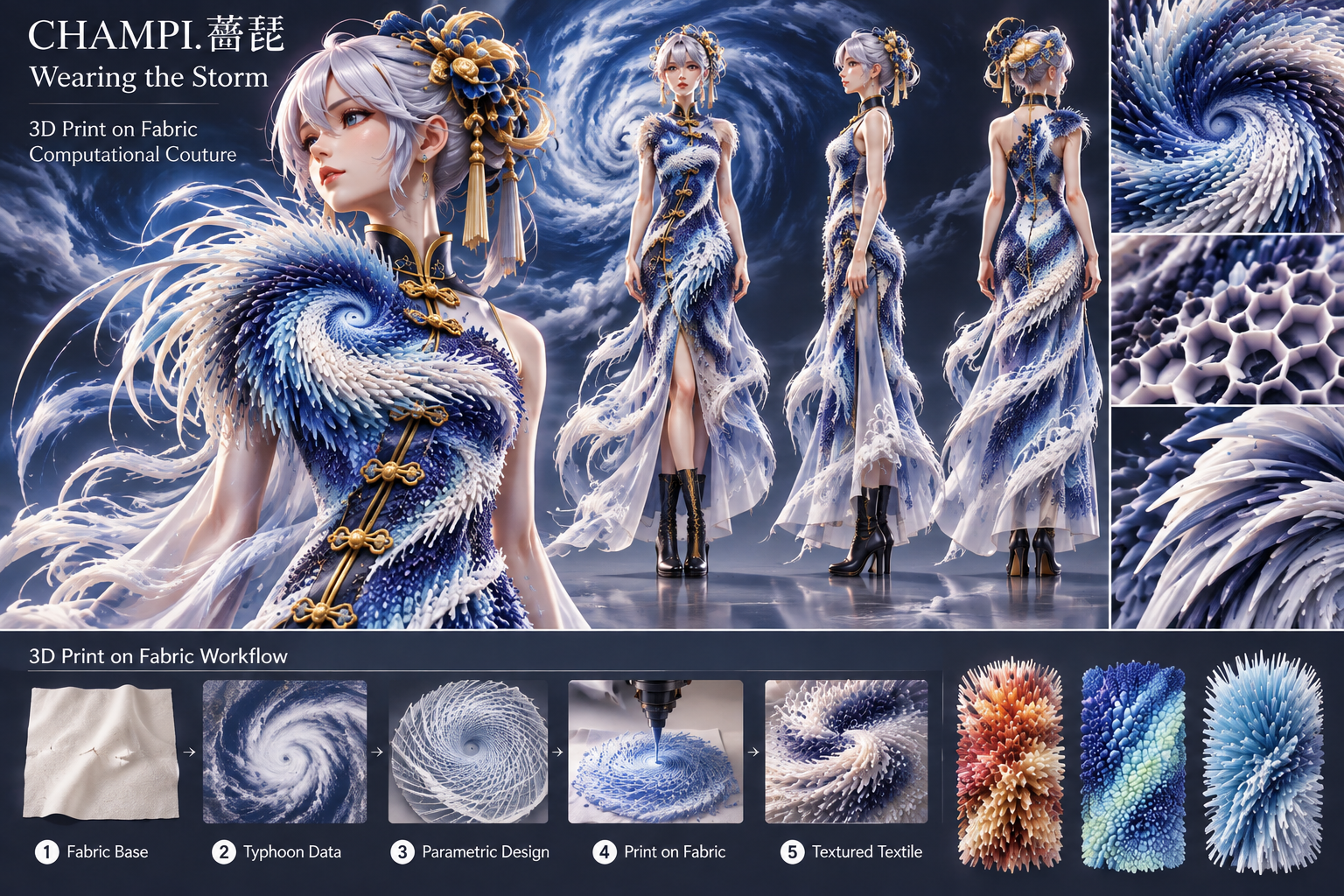
Inspired by the lecture of Julia Koerner, I wanted to explore another approach to computational couture: What if I could translate the movement and intensity of a typhoon directly onto the surface of a fabric? Her examples of 3D-printed textile surfaces featuring spikes, organic growth patterns, and complex texture sent me into imagining a garment that could physically express the turbulence of a storm.
The central design inspiration comes from the spiral structure of a tropical cyclone. Using Blender and computational design techniques, I aim to translate different characteristics of a typhoon into physical surface textures:
- Eye of the Storm: A concentrated spiral pattern, where the geometry converges toward a central point.
- Spiral Rainbands: Curving, directional ridges and fins that flow across the fabric, following the rotational movement of the storm.
- Wind Intensity: Variations in the height, density, and orientation of 3D-printed spikes to suggest changing wind strength.
- Cloud Formation: Organic, porous, and clustered geometries inspired by turbulent cloud structures.
I want to develop small material samples and evaluate their printability, adhesion, and flexibility. This is how I want to use CHAMPI to explores how an invisible natural force can be translated into something tactile, wearable, and expressive — turning the movement of a typhoon into the texture of a garment.
2. Using a 3D Printer
Experiment 01 — Getting Started with the Bambu Lab P1S
I recently bought a personal Bambu Lab P1S with Automatic Material System (AMS), so I could explore multi-color FDM 3D printing at home. I set it up, went through calibration processes.
What is AMS
The Automatic Material System (AMS) allows multiple filament spools to be loaded and automatically switches between them during printing according to the prepared slicing instructions.
One thing I particularly appreciated about the Bambu Lab ecosystem was its hardware/software interface.
Bambu Lab provides a mobile application called Bambu Handy, which allows users to connect to and monitor compatible printers from their phones. After pairing the printer with my account, the app provided a convenient way to manage printing activities without constantly operating the machine's physical interface.
I was also interested in the wider digital ecosystem surrounding the printer. Through a Bambu Lab account and its connected software, users can access supported printing records and device information. The MakerWorld platform provides an extensive community library of downloadable 3D models, print profiles, and projects shared by makers around the world.
For someone experimenting with digital fabrication, this combination of hardware, software, and community resources makes it much easier to get started by leverating existing community designs before developing original ones.
In my first print, I actually ended up with a tangled mass of white filament. Then I had to struggle a bit with calibration to really understand the printer and had to fix some broken cover from the nozzle head.
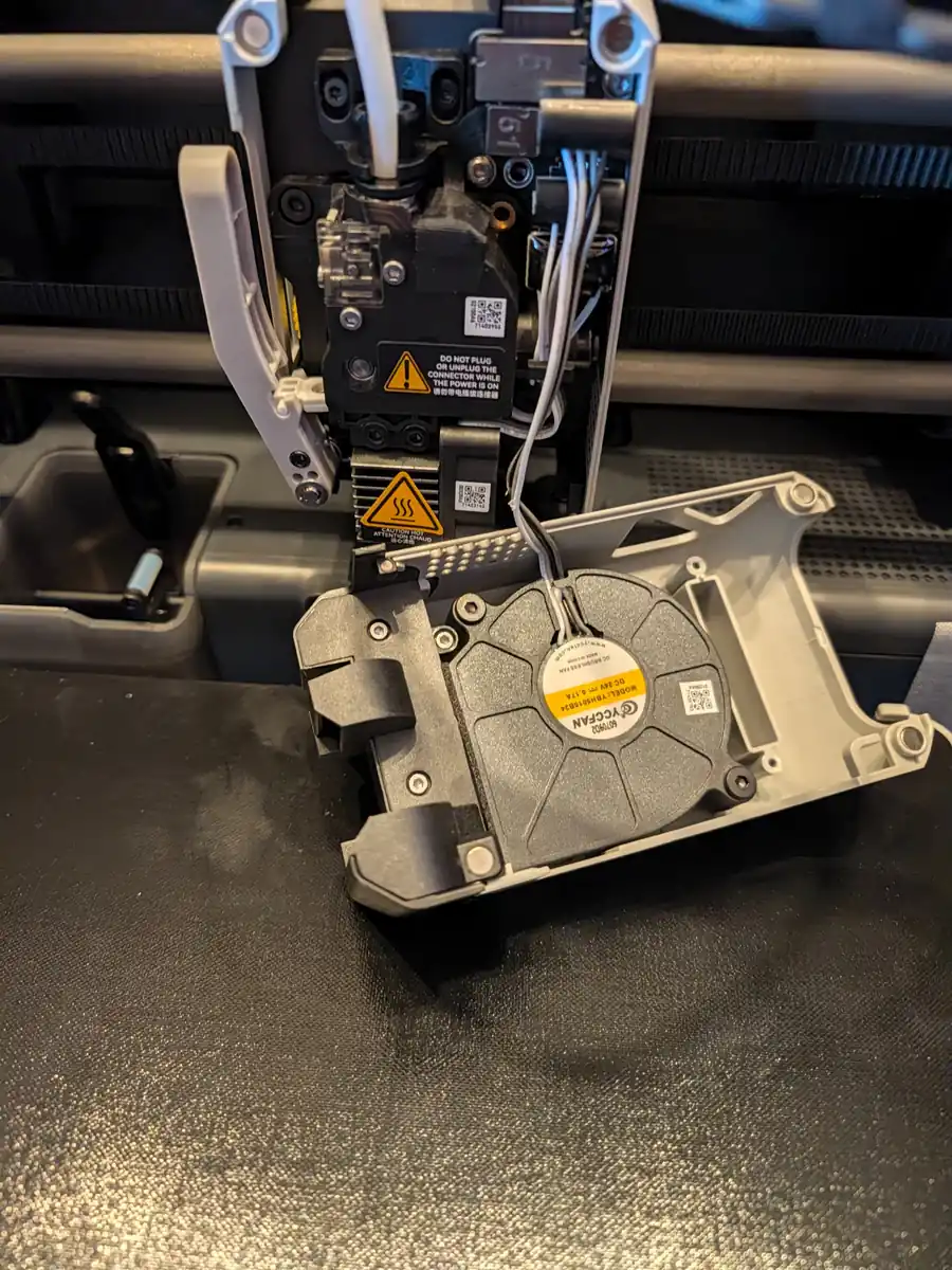
Troubleshooting — Repairing the Printhead Cover
During my initial exploration of the Bambu Lab P1S, I encountered an unexpected hardware issue: the printhead's front cover had come loose.
Instead of immediately moving on to the next print, I took time to inspect the toolhead assembly and understand how its components fit together. I checked the cover, cooling fan, and cable connections before carefully reattaching the cover, and performed multiple rounds of calibration.
This became another valuable part of my learning process. Digital fabrication is not just about preparing 3D models and pressing Print — it also requires understanding the physical machine, diagnosing problems, and performing basic maintenance. Becoming comfortable with troubleshooting the printer is just as important as learning how to design for it.
I was eventually able to successfully print a multi-colored articulated dragon featuring green, white, and orange sections (the original model from MakerWorld was different, the AMS system and Bambu software adjust to the actual printer spool color easily)
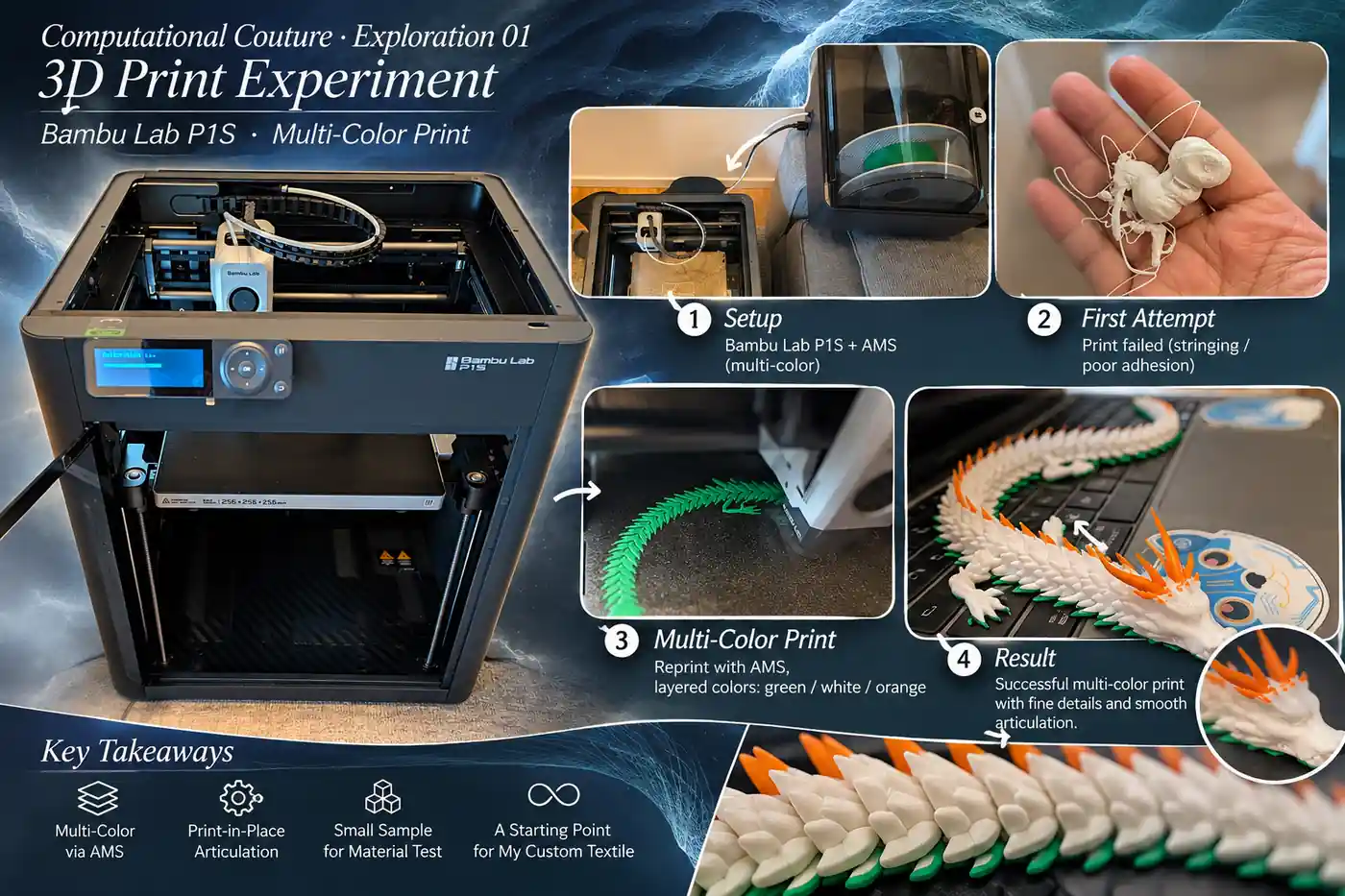
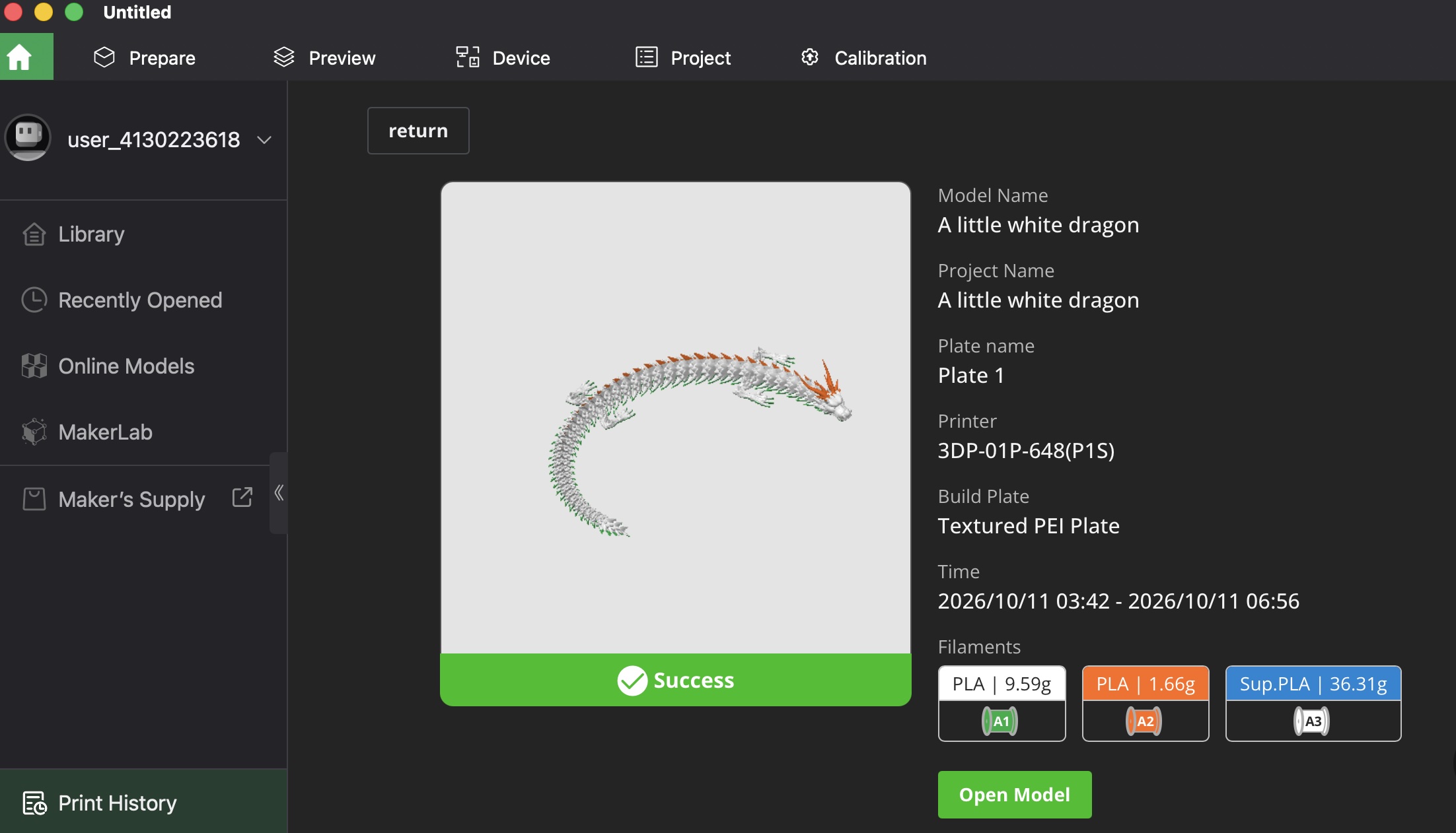
This was particularly interesting because the dragon was designed with multiple connected segments that could move relative to one another after printing.
The result helped me better understand the potential of print-in-place articulation — creating interconnected moving structures within a single fabrication process, without manually assembling every segment afterward.
Although the dragon itself is not a textile, its segmented construction offers a useful reference for computational couture.
3. From Geometry to G-code
Experiment 02 — Generating a Computational Textile with Filafabric
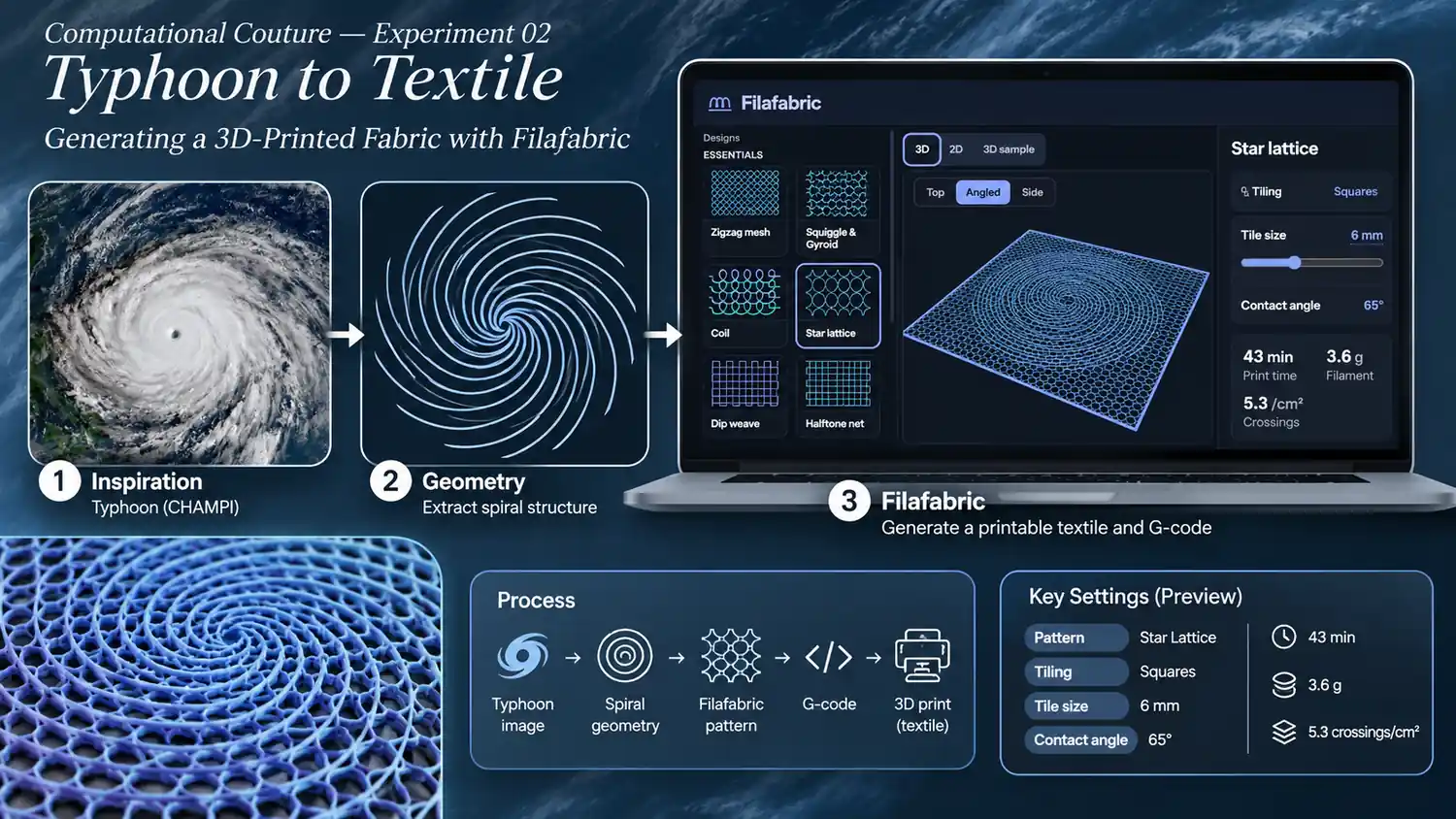
My next step was to try to creating a flexible textile pattern derived from my own design inspiration - which is the typhoon.
I found satellite image of a typhoon. The geometry of the storm itself is beautiful. From above, a typhoon reveals an extraordinary natural structure: a clearly defined central eye, surrounded by rotating cloud bands that spiral outward.
Parametric Design
For spirals, there are 3 key geometric characteristics:
- The eye: A relatively open central region.
- Spiral rainbands: Curved structures rotating around the eye.
- Radial expansion: The increasing distance between the center of the storm and its outer cloud formations.
These characteristics are the foundation of my parametric model.
To reproduce the rotational structure of the typhoon, I explored a mathematical spiral defined using polar coordinates.
In a polar coordinate system, each point is described by its distance from the center (radius) and its angular position.
Mathematical Foundation — The Archimedean Spiral
To translate the rotational movement of a typhoon into computational geometry, I used an Archimedean spiral as a mathematical reference.
The Archimedean spiral:
Converting to Cartesian coordinates:
01 — Defining the Spiral
The spiral is described using polar coordinates, where each point is defined by its distance from the center and its angle of rotation.
| Parameter | Description | Design Influence |
|---|---|---|
| \(r\) | Radial distance | Distance from the storm's eye |
| \(\theta\) | Rotation angle | Position along the spiral |
| \(a\) | Initial radius | Controls the size of the storm's eye |
| \(b\) | Radial growth rate | Controls the spacing between spiral turns |
02 — Converting to Cartesian Coordinates
To generate the spiral as a 2D vector path, the polar coordinates are converted into Cartesian coordinates:
These equations calculate the X and Y positions of points along the spiral, allowing the geometry to be generated computationally and exported as SVG.
Why Parametric Design?
Instead of manually drawing every curve, I can modify the spiral by changing just two parameters:
- Increase \(a\) → Create a larger storm eye.
- Increase \(b\) → Create wider spacing between spiral turns.
This allows me to generate multiple variations of the CHAMPI textile while preserving its underlying typhoon-inspired geometry.
By changing the parameters, I can generate different spiral structures without manually redrawing the geometry.
For example, increasing the number of rotations creates a denser vortex, while increasing the radial spacing produces wider spiral bands.
So the key design parameters included:
- Overall diameter: Defines the size of the textile sample.
- Eye radius: Controls the open space at the center.
- Number of spiral arms: Determines the visual density of the storm.
- Spiral rotation: Controls the amount of twisting.
- Line spacing: Influences the distance between neighboring strands.
- Line thickness: Determines the intended width of the printed features.
Result SVG file for fabrication

Next Steps
From Flat Geometry to Parametric Wearable Textiles
At this stage, my CHAMPI — Wearing the Storm textile design is still largely two-dimensional. Although I have successfully translated the visual language of a typhoon into circular spiral patterns and experimented with digital fabrication, the geometry remains flat and is not yet fully parametric.
This presents an important limitation: a textile designed on a flat surface does not automatically conform to the complex curves of the human body. For computational couture, I want to move beyond creating decorative patterns and begin designing textile structures that respond to the body's shape, proportions, and movement.
My next step is to continue following a Rhino and Grasshopper tutorial that demonstrates how to work with a digital human body mesh. Grasshopper's visual programming environment will allow me to develop a more systematic, parametric workflow rather than manually modifying individual geometric elements.
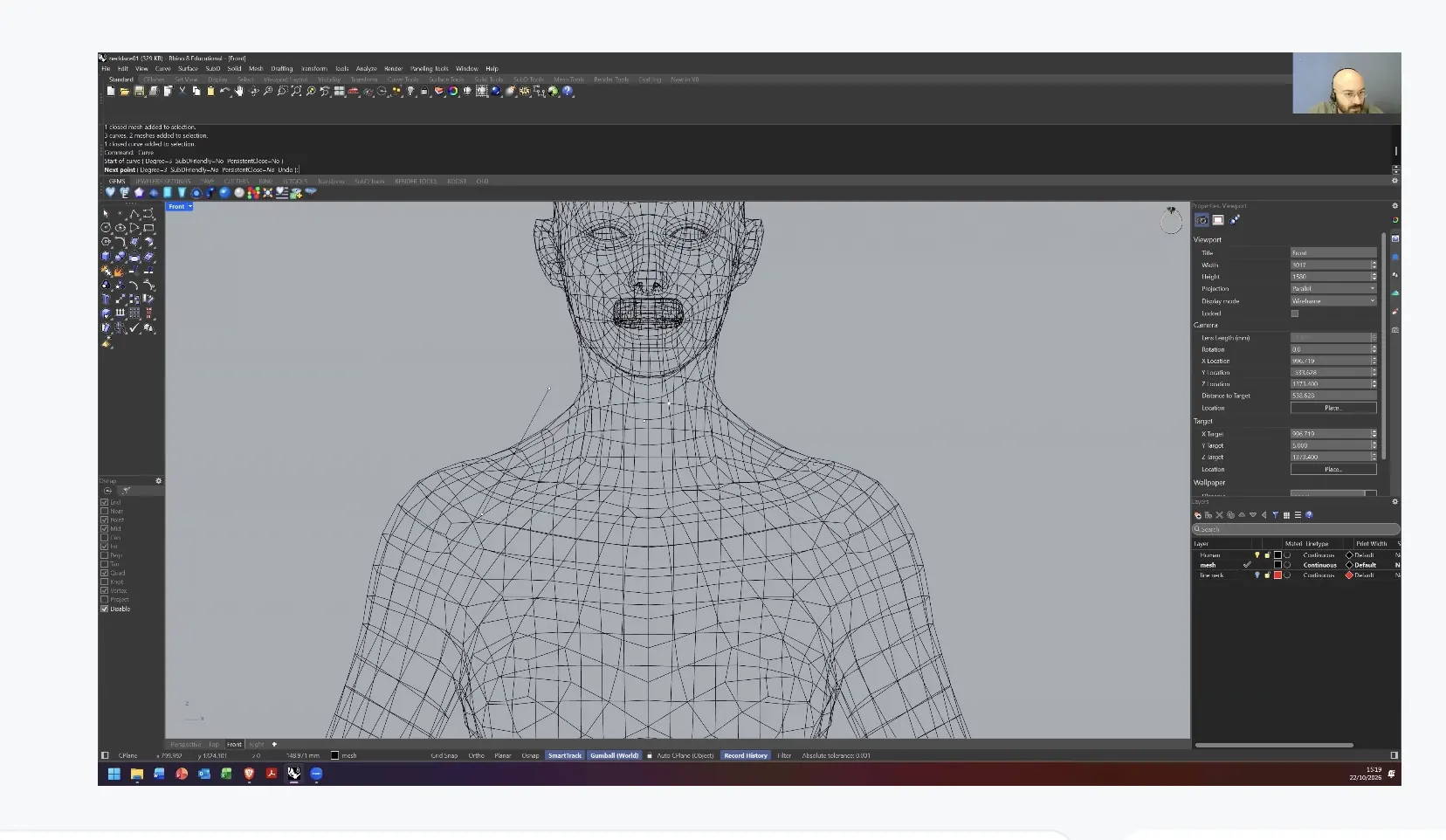
I plan to explore how to:
- Import and prepare a digital human body mesh as the reference surface for garment development.
- Generate parametric textile patterns** with adjustable dimensions, spacing, density, and connections.
- Map my typhoon-inspired spiral geometry onto a three-dimensional body surface**, beginning with the torso.
- Adapt the geometry to body curvature**, investigating how individual textile units deform or change orientation across the surface.
- Evaluate flexibility and fabrication constraints, including connection tolerances, articulation, and how the printed structure might behave when worn.
The ultimate goal is to transform CHAMPI from a flat, storm-inspired pattern into a body-responsive computational textile that integrates the visual movement of a typhoon with the functional requirements of wearable design.
This remains a work in progress. My current experiments establish the foundation for fabrication, while the next phase will focus on parametric modeling and three-dimensional garment development.
Exploring Filafabric
Afterwards I used Filafabric, a computational textile design tool that generates 3D-printing paths for flexible fabric-like structures.
Filafabric offers a library of geometric patterns, including zigzag meshes, coils, lattices, and Turing-inspired structures. These patterns explore how continuous printed strands and their intersections can form flexible textile-like surfaces.
I imported the SVG file into Filafabric and explored its Star Lattice structure (no particular reason, just trying out), using a square tiling arrangement and a 6 mm tile size.
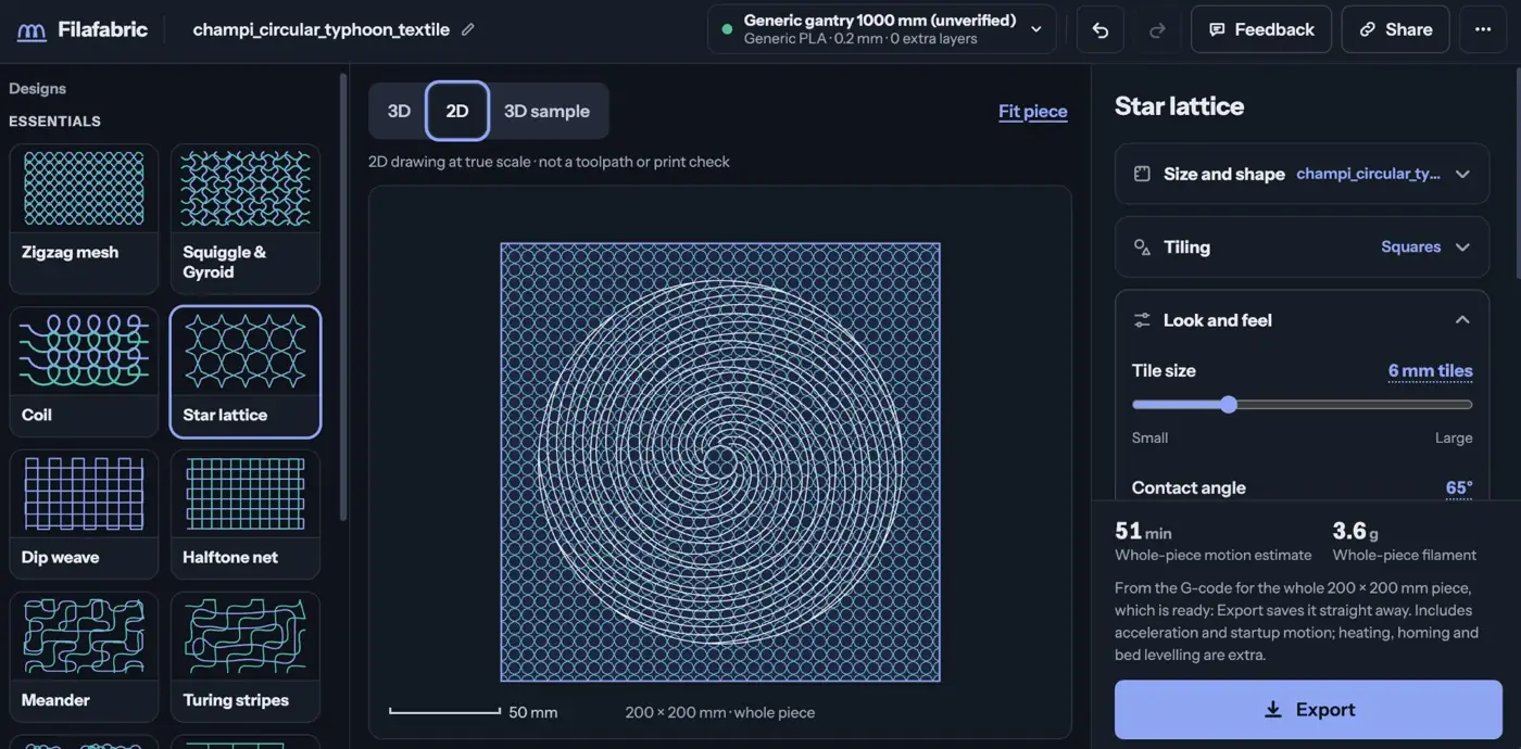
The resulting preview combined the storm-inspired spiral with a dense network of interconnected geometric lines, producing a textile pattern that visually echoes the rotational movement of the typhoon.
One of the most interesting aspects of Filafabric is that it approaches textile fabrication through the actual movement of the printer nozzle (as in the tutorial Jose explained all principles are X, Y, Z coordinated CNC)
Instead of treating the design only as a conventional solid 3D model, the software generates printing paths that determine how filament is deposited layer by layer.
The preview distinguishes between the first layer and subsequent layers, allowing me to investigate the relationship between strand placement, intersections, and the resulting textile structure.
This was my first attempt parameters:
- Pattern: Star Lattice
- Tiling: Squares
- Tile size: 6 mm
- Contact angle: 65°
- Estimated printing time: 43 minutes
- Estimated filament consumption: 3.6 g
- Crossing density: 5.3 crossings/cm²
Result Gcode
Takeaway
With Filafabric, I realized the geometry of the printing path itself could determine the flexibility and behavior of a material.
4. Printing at Fab Lab Taipei
Since I'm remote this week in Taipei, I reached out to Ted from Fab Lab Taipei to use the machines at the lab. He generously gave me access to an ELEGOO Centauri Carbon 2. This gave me an opportunity to compare two different 3D-printing ecosystems: Bambu Lab, which I had previously used, and ELEGOO, a new brand that I have never used before.
Also, I wanted to understand how a rigid 3D-printing material could be transformed into a flexible, fabric-like structure through geometric design first. Rather than immediately designing a complex textile from scratch, I chose to do an existing print-in-place model to understand how repeated geometric units, mechanical connections, and carefully designed clearances could create flexibility.
Experiment 03 - Cross-Platform 3D Printing: From MakerWorld to ELEGOO
I selected the Flexi Fabric – Easy Print model on MakerWorld as a starting point.
Although both Bambu and ELEGOO machines use fused-filament fabrication, their machine configurations, firmware, and slicing profiles are not automatically interchangeable.
So the overall cross-platform workflow was:
- Download the model from Bambu MakerWorld.
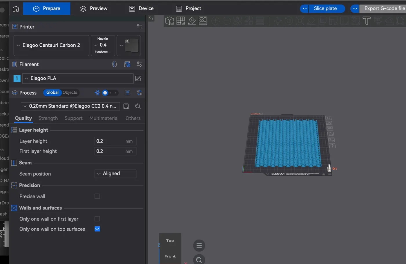
- Import the model into ELEGOO Slicer.
- Select the correct ELEGOO Centauri Carbon 2 printer profile.
- Confirm the nozzle diameter and installed filament.
- Review layer height, support generation, build-plate adhesion, and printing orientation.
- Slice the geometry using the ELEGOO machine configuration.
- Inspect the toolpath preview before exporting G-code.
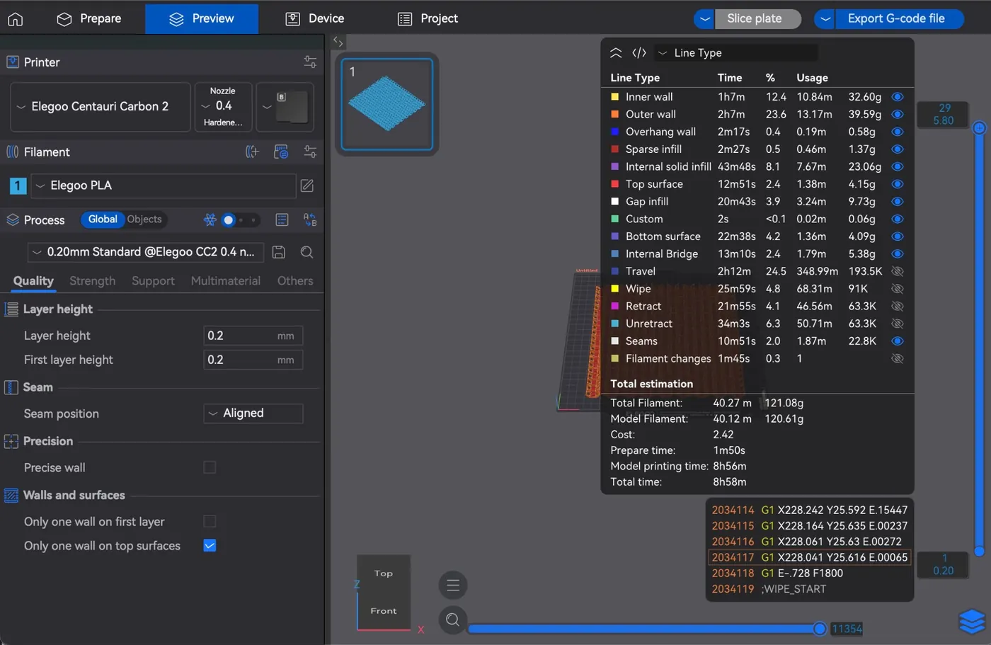
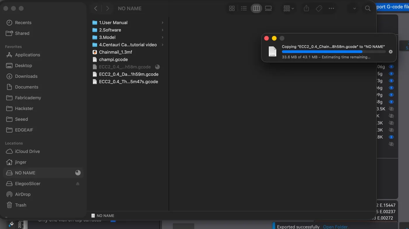
Step 1 — Downloading the model
I downloaded the model first from MakerWorld. There are 2 options (STL vs 3MF), and I downloaded both. But in the STL, there is only the small swatch sample, but for 3MF, there is small swatch and the big footprint model.
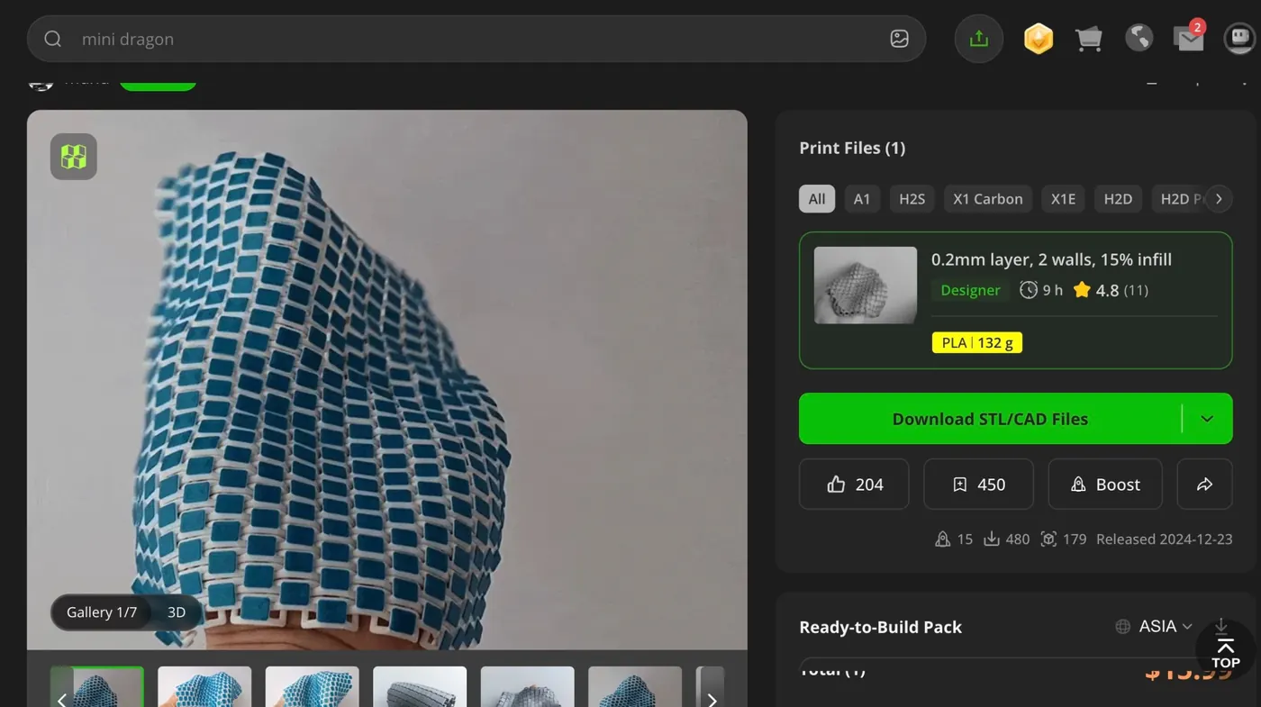
STL vs 3MF
Unlike STL, which primarily describes mesh geometry, 3MF is a more comprehensive 3D-manufacturing file format. Depending on how the file is prepared, it can contain multiple objects, materials, colors, and print-related metadata.
The model was downloaded from the Bambu Lab ecosystem, but I wanted to fabricate it using a different manufacturer's printer. A MakerWorld 3MF may include Bambu-specific printer profiles and slicing settings, which are not necessarily compatible with an ELEGOO printer.
The challenge was therefore to separate the reusable design geometry from the machine-specific fabrication instructions. In the USB drive, each model has its own folder with STL and G-Code.
Step 2 — Downloading the ELEGOO Slicer
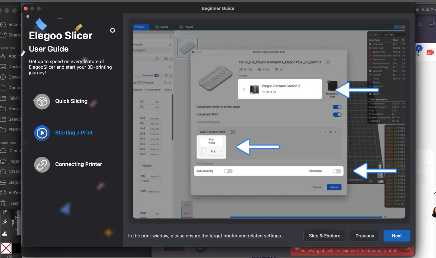
Then I have to download ELEGOO Slicer for the ELEGOO Centauri Carbon 2 here at Fab Lab Taipei.
Step 3 — Importing the model into ELEGOO Slicer
The next step was to open the downloaded model file in the ELEGOO slicer and reslice. The key consideration was to retain the original model geometry while replacing any incompatible Bambu Lab print settings. For the initial test, my objective was to preserve the model's intended geometry and evaluate whether its connections could be printed successfully on the ELEGOO machine.
Understanding the Importance of Print Settings
Print-in-place textile structures are especially sensitive to printing parameters.
Unlike a conventional solid object, the model contains small gaps and connecting features that allow adjacent
Step 4 - Preparing Machine-Specific G-code
After checking the slicing configuration, slice -> export -> load it up into the USB stick, then send it to printer.
G-code
G-code describes the printer's movement, extrusion, temperature control, and other machine operations.
The same 3D geometry can often be printed on different machines, but the G-code must be generated for the specific printer and fabrication setup.
Result 1: Testing a small swatch sample The small swatch print-in-place sample was very successful, although on PLA, the flexibility and texture is neat.
Result 2 - Scaling up was a failure.
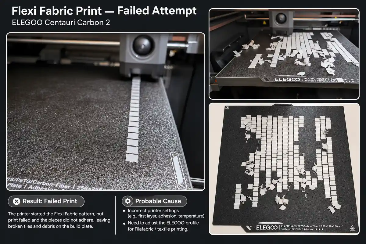
Once I sacled it up to a bigger area print, the print failed. The result suggests that the model geometry is processed, but the fabrication settings still required adjustment. Potential issues included first-layer adhesion, Z-offset calibration, nozzle temperature, and print speed. A friend suggested that the first-layer adhesion problem could well be solved by cleaning the bed with isopropsyl alcohol. I have not tried yet as I ran out of time, but he will also try to help me print a copy on his Bambu to compare the difference.
This experiment reinforced how important machine-specific slicing and calibration are when producing print-in-place textiles. Unlike conventional solid objects, flexible structures contain many small, independent elements, making consistent bed adhesion especially critical.
Experiment 04 - 3D Printing Fabric
On the Filafabric - since there is no ELEGOO options yet available, I had to sort back to "Generic gantry 1000 mm (unverified)" option. I'm also limited what filament is available here, it has to be PLA.
I loaded up the G-Code from Filafabric output to the printer.
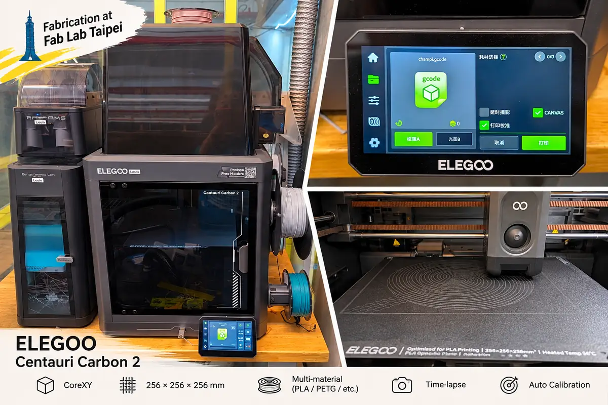
Result - The first printing attempt failed. The Nozzle Drew the Storm, but Without Filament.
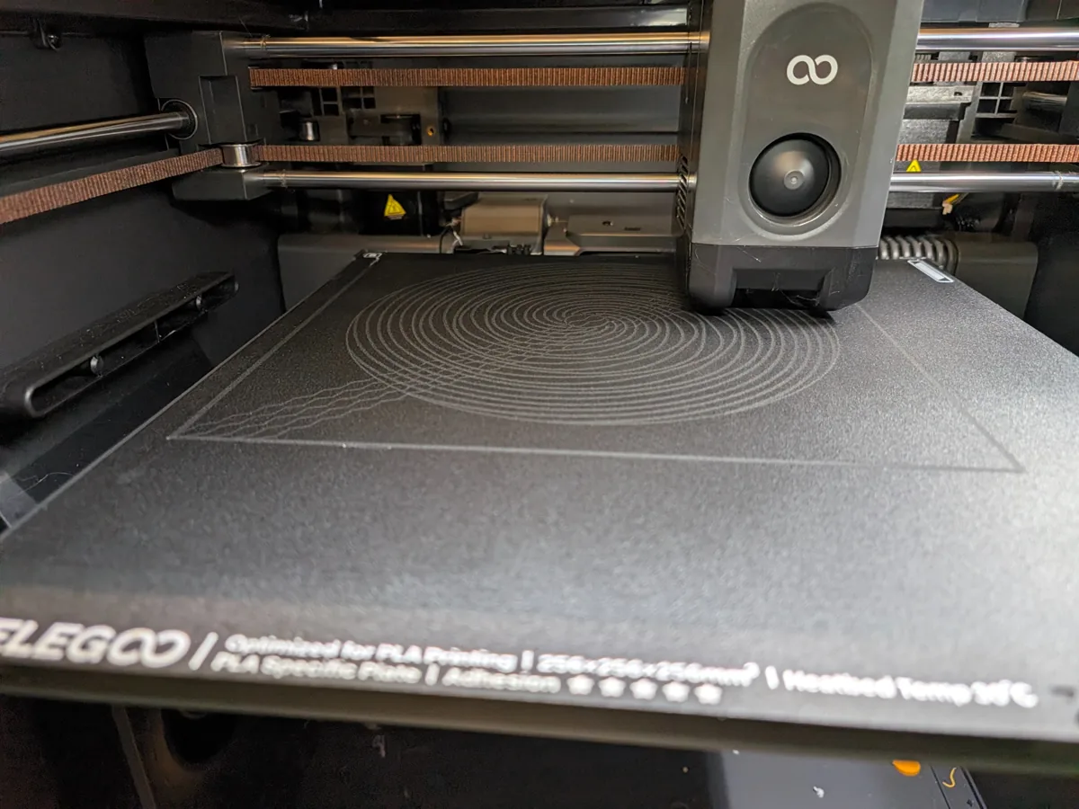
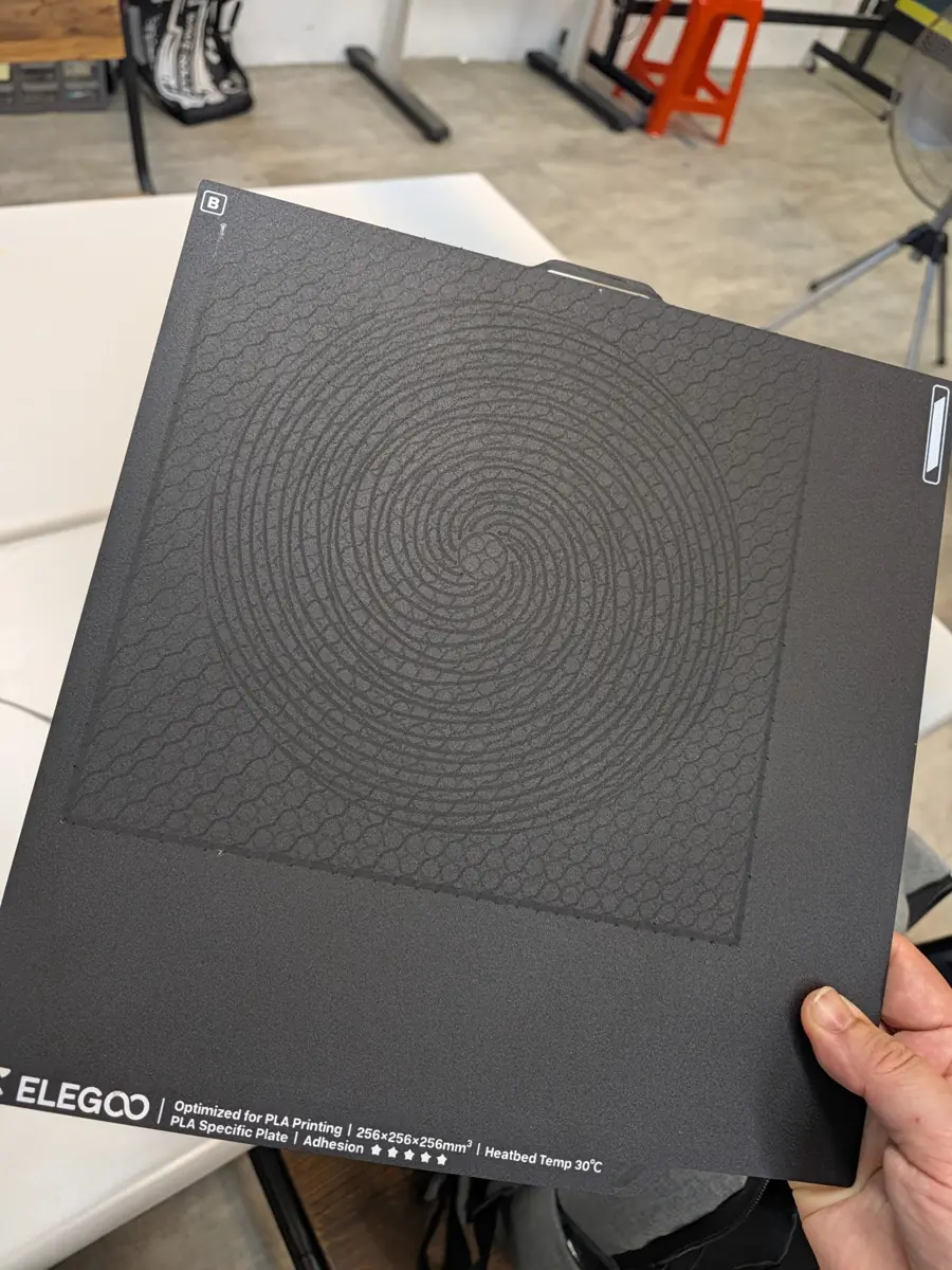
The printer successfully followed the spiral toolpath, reproducing the circular geometry of my typhoon design. However, no filament was deposited. Instead, the nozzle moved directly against the build plate, leaving physical impressions that traced the storm pattern.
When I removed the build plate, I could clearly see the spiral and surrounding lattice. What initially looked like an extremely thin printed structure was actually a series of marks made by the nozzle itself.
In other words, the printer had drawn my design onto the build plate rather than printing it in plastic.
Troubleshooting — From Toolpath to Material Deposition
This result helped me separate two aspects of digital fabrication:
- Motion control: The printer was able to interpret and follow the generated XY geometry.
- Extrusion and Z-axis control: The machine did not deposit material, and the nozzle appeared to contact the print surface.
I suspect that the G-code generated through Filafabric was not correctly configured for the ELEGOO Centauri Carbon 2 because Filafabric mainly had profiles ready for Prusa and Bambu, and this is a new/unsupported printer.
This failure was an important lesson in computational fabrication. A successful digital toolpath does not guarantee a successful physical print.
The experiment demonstrated that my typhoon geometry could be translated into machine movement, but also exposed the risks of using G-code without verifying printer-specific settings.
Before continuing, I need to establish a compatible Filafabric configuration, verify extrusion and Z-height, and test the design on a much smaller sample.
But since I only have limited time at Fab Lab Taipei on Sunday, my time for experiment and troubleshoot ran out. I would like to continue explore with different configs or try on different printers. The next step is to test whether this computational pattern can be successfully fabricated as a flexible textile, and to evaluate its movement, durability, and figure out the assembly method turning into a full garment.
5. Reflections
A Digital Design Is Not the Same as a Printable File
My biggest takeaway this week was understanding the difference between transferable digital geometry and machine-specific manufacturing instructions.
My first mistake was surprisingly basic: after downloading a model from MakerWorld, I immediately copied the STL file onto a USB drive, plugged it into the 3D printer, and couldn't understand why the model wasn't appearing on the printer's interface!
I quickly learned that an STL describes the geometry of an object, but it does not tell the printer how to manufacture it. The model must first be processed through a slicer to generate compatible G-code, taking into account the specific machine, material, and printing parameters.
This experience reminded me that digital fabrication is not simply downloading a file and pressing Print. Understanding the workflow between design and fabrication is just as important as creating the design itself.
Computational Couture Requires Both Digital Precision and Physical Reliability
Online platforms have made it incredibly easy to share, remix, and customize designs. However, successfully manufacturing those designs still depends on the relationship between geometry, material properties, slicing parameters, and hardware.
This became particularly evident in my experiments with Filafabric and Flexi Fabric. My typhoon-inspired geometry could be translated into printer movements, but incorrect machine configuration resulted in the nozzle leaving impressions on the build plate instead of extruding filament. In another experiment, the Flexi Fabric tiles began printing but detached from the bed before the textile could be completed.
For computational couture, these challenges are especially significant. Unlike a conventional solid 3D print, a flexible textile relies on hundreds of small elements, joints, and connections working together. A single failed connection can compromise the flexibility, durability, or integrity of the entire structure.
A computational textile is not truly successful until its digital flexibility becomes physical flexibility.
The Global Fab Lab Network Is as Valuable as the Machines Themselves
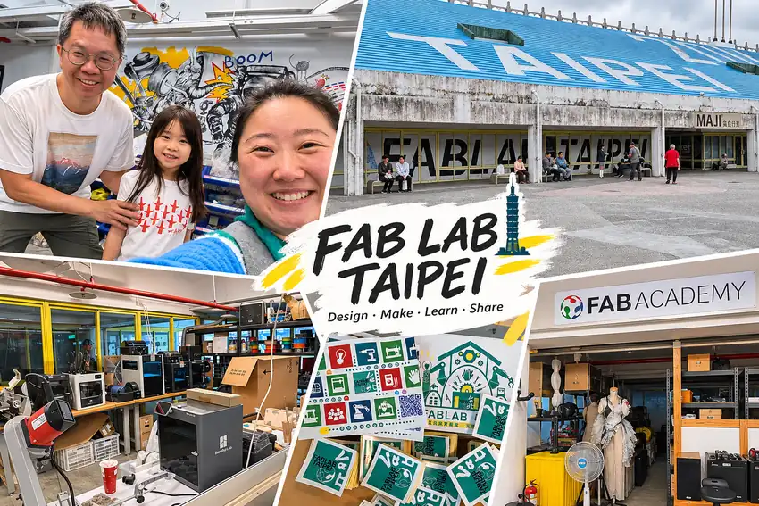
A huge thank-you to Fab Lab Taipei for generously hosting me this week and giving me access to its facilities and 3D printing equipment.
One of the most meaningful parts of my Fabricademy journey has been experiencing the generosity of the global Fab Lab network firsthand. Wherever I go, I continue to encounter people who are willing to share their knowledge, open their workshops, and support someone else's learning process.
This week reminded me that digital fabrication is not only about machines, software, and technical skills. It is also about the communities that make experimentation and knowledge exchange possible.
Even when my prints fail, I walk away having learned something new—and often having met wonderful people along the way.
I feel incredibly fortunate to be part of a global community where curiosity is welcomed, knowledge is shared, and learning can happen anywhere.