Computational Couture
00 Assignment
- Research and document inspiration, concepts and sketches, including artistic or scientific references on 3D printing and parametric design.
- Create a parametric model using Grasshopper, Blender or another parametric design tool.
- Document the workflow from parametric modelling to exporting and preparing the design for 3D printing.
- Document the printer preparation, G-code generation and printing settings step by step.
- Create samples of 3D-printed textile structures or print directly onto fabric.
- Document the printing process and the final results.
- Upload the 3D design files, parametric files and STL files.
01 Inspiration & Research
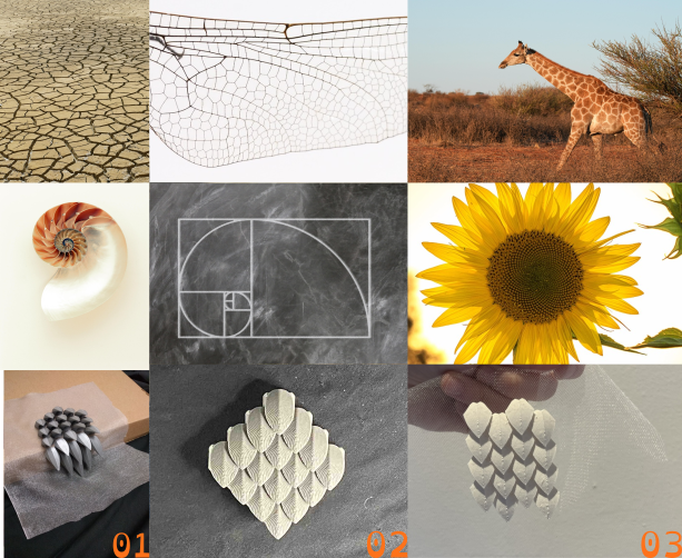
01 Dragon Scales – Shorey Designs
02 Computational Couture – Gabríella Kamí Árnadóttir
03 Computational Couture – Carolina Beirão
To get a better understanding of Grasshopper, I wanted to follow a more structured approach instead of jumping from one YouTube tutorial to the next. I therefore worked through selected chapters and exercises from the book AAD Algorithms-Aided Design by Arturo Tedeschi. This helped me understand the basic principles of parametric design and how different Grasshopper components work together.
04 AAD Algorithms-Aided Design – Arturo Tedeschi
This week, I wanted to explore how repeated shapes can become flexible textile surfaces and how a flat pattern can influence a three-dimensional form. My starting points were the dragon scales I had developed in Week 3 and the mathematical patterns I noticed in nature.
I wanted to return to the dragon scales because I was still interested in their overlapping structure and the way individual elements move together. After making them from felt in Week 3, I wanted to explore what 3D printing could add to the idea. I looked at Shorey Designs’ Dragon Scales and the Fabricademy experiments by Gabríella Kamí Árnadóttir and Carolina Beirão to see how they combined printed scales with fabric. Their examples made me think about how the shape and spacing of the scales, together with the choice of fabric, could change the flexibility and appearance of the surface.
This interest in repeated elements also led me to look more closely at patterns in nature. In a sunflower seed head, individual seeds form interwoven spirals whose counts often correspond to neighbouring Fibonacci numbers. I find it fascinating how a simple arrangement can create such a complex pattern. The spiral shapes of snail shells interested me for a similar reason: they gradually increase in size while maintaining a recognisable form. Although these shells are better described as approximately logarithmic spirals rather than exact Fibonacci spirals, they offered another starting point for exploring growth, repetition and changing proportions in Grasshopper.
Alongside these spirals, I was drawn to the irregular networks found in dragonfly wings, giraffe coat markings and cracked, dried ground. Despite their different origins, they all divide a surface into connected areas of varying shapes and sizes. They reminded me of Voronoi patterns, where the position of individual points determines the boundaries of the surrounding cells. These natural examples are not necessarily exact Voronoi diagrams.
Together, these references gave me two directions to explore: individual printed elements that move with the fabric, and connected patterns that influence the fabric’s shape. By printing mathematical patterns onto stretched fabric, I wanted to investigate what happens when the tension is released. I was curious to see how the placement of printed lines and open spaces could make a flat textile bend, gather or develop an unexpected three-dimensional form.
02 Getting Started with Grasshopper
For this week, I decided to work with Rhino and Grasshopper because I already had some experience with both programs. This meant I did not have to start completely from scratch and could focus more on experimenting with parametric designs.
3D modelling software for creating and editing precise geometries, surfaces and complex shapes.
Installation and Setup
Grasshopper is already included in Rhino. To activate it, I followed these steps:
-
Open Rhino and go to Tools → Options → Plug-ins.
-
Search for Grasshopper in the list of available plug-ins.
-
Make sure Grasshopper is enabled and load the plug-in if necessary.
-
Type Grasshopper into the Rhino command line and press Enter.
After activating Grasshopper, I could open its visual programming interface alongside Rhino.
Grasshopper allows me to connect components and create parametric geometries. Changes to parameters are immediately visible in the Rhino viewport.
Getting Started with Grasshopper
The interface consists of two main parts: the Grasshopper canvas, where the components are connected, and the Rhino viewport, where the resulting geometry is displayed.
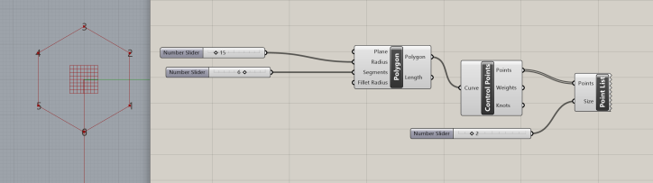
To understand the basic workflow, I created a simple polygon.
-
Adding components: Double-clicking on the Grasshopper canvas opens a search field where components can be added.
-
Number Sliders: These allow parameters to be changed without modifying the definition. In this example, I used sliders to control the polygon's radius (15) and number of segments (6).
-
Connecting components: Each component has inputs on the left and outputs on the right. Connecting them with wires passes data from one component to another.
-
Control Points: I connected the polygon to a Control Points component to extract its vertices.
-
Point List: This component displays the index of each point in the Rhino viewport. An additional slider controls the size of the displayed numbers.
Changing a slider immediately updates the geometry in Rhino. This makes it possible to experiment with different shapes without rebuilding the entire design.
This basic principle of connecting components and controlling parameters will also be used in my following experiments.
04 Dragon Scales
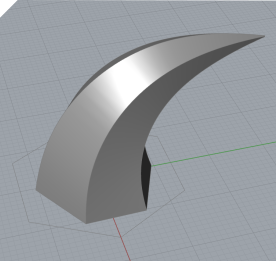
My goal was to create a parametric dragon scale that I could later use to cover larger surfaces. Instead of designing each scale individually, I wanted to develop a flexible base shape that could be modified by changing a few parameters.
This would allow me to generate scales with different sizes, proportions and curvatures while keeping the same basic design. In a later step, I want to arrange these scales across a surface and experiment with how changing the parameters affects the overall appearance.
Creating a 3D Scale V1
For my first attempt, I started with a simple hexagon as the base geometry. By moving individual vertices, I changed its proportions to create a wider shape with a more pointed end.
Next, I created a curved line using control points. Initially, I used only three points, but during the design process I realised that I needed a fourth point. This allowed me to adjust the curvature while keeping the base of the scale in its original position.
Along this curve, I placed several copies of the modified hexagon, gradually decreasing their size towards the tip. By connecting these cross-sections, I created a three-dimensional scale.
The resulting design had several adjustable parameters:
- Base size: Controls the dimensions of the scale.
- Tip position: Changes the position of the pointed end.
- Curvature factor: Adjusts how strongly the scale bends.
- Position: Controls the placement of the geometry.
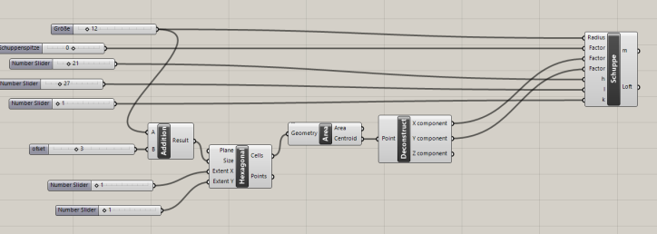
However, I quickly realised that the result did not really match what I had imagined. The definition had also become more complicated than necessary. Small changes to certain parameters could cause long calculation times or produce unexpected and distorted shapes.
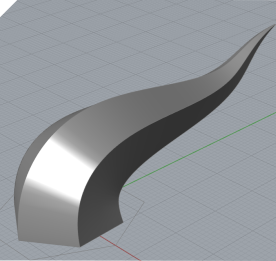
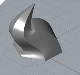
Although the experiment helped me understand how to construct a three-dimensional shape from multiple profiles, I decided to try a simpler approach for the next version.
Creating a Custom and Reusable Component
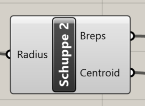
As my Grasshopper definition grew, it became increasingly difficult to keep track of all the connected components. To make the definition easier to understand and reuse my scale in other projects, I decided to create a custom component.
Grasshopper offers two useful functions for this: Clusters combine multiple components into a single block, while User Objects allow these blocks to be saved and reused in other Grasshopper files.
Creating a Cluster
- Select all the components you want to combine.
- Go to Edit → Cluster Selection or use the Cluster option in the radial menu.
- Grasshopper replaces the selected components with a single Cluster.
- The connections to the remaining components become the inputs and outputs of the Cluster.
- Double-click the Cluster to open and edit its internal definition.
- Rename the Cluster and its inputs and outputs to make their functions easier to understand.
I kept the adjustable parameters outside the Cluster so I could continue modifying the scale without opening its internal definition.
Saving the Cluster as a User Object
To make the Cluster available in other Grasshopper projects, I saved it as a User Object.
- Select the Cluster.
- Go to File → Create User Object.
- Enter a name, description and category for the component.
- Optionally assign a custom icon.
- Save the User Object.
The custom component is now available in the Grasshopper toolbar under the selected category and can be inserted into other definitions.
This approach keeps my Grasshopper canvas organised and allows me to reuse the scale design without rebuilding it. I can also create multiple instances of the same component with different parameters, which will be useful when arranging scales across larger surfaces.
Creating a 3D Scale V2
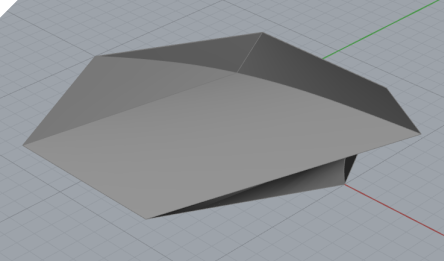
For my second version, I wanted to create a flatter shape that looked more like a traditional dragon scale rather than a horn. The individual scales should still be able to overlap when arranged next to each other.
I started again with a hexagon as the basic shape. This time, I kept the original six-sided geometry and only made the radius adjustable. Unlike the first version, I wanted to keep the design simple, with just one parameter controlling the size.
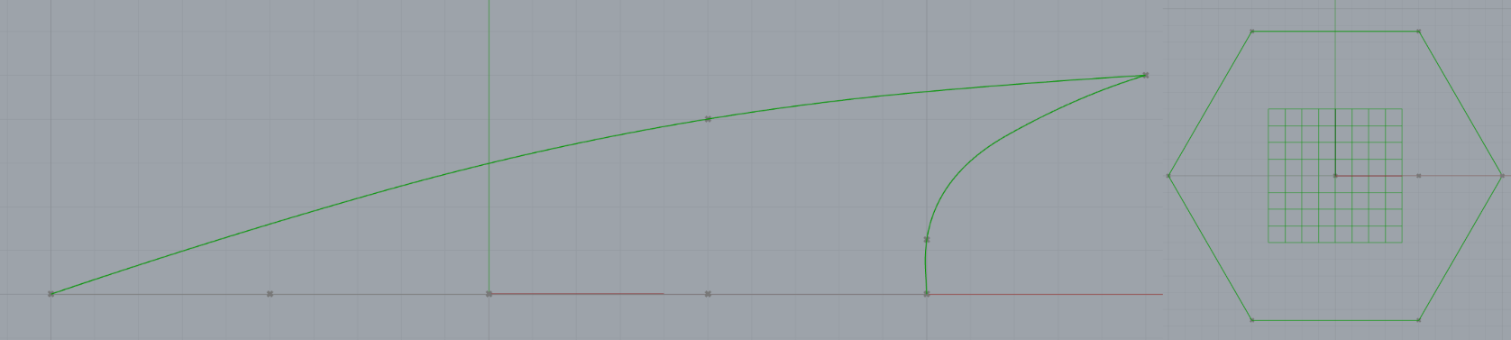
I then calculated the centroid of the hexagon and moved it upwards, beyond one of the vertices. This new point would form the extended tip of the scale.
To avoid straight edges, I created two interpolated curves using additional control points. These allowed me to introduce a gentle curvature on both sides of the scale, giving it a more organic shape.
Finally, I used Edge Surface to create the individual surfaces between the curves and the edges of the hexagon. I then joined these surfaces into a single Brep using Brep Join.
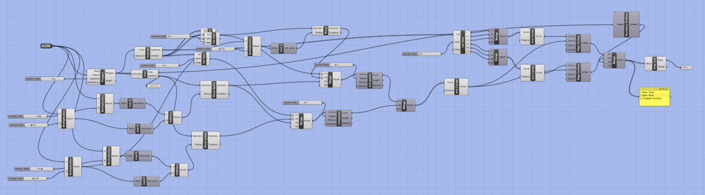
The Grasshopper definition shows the complete construction, starting with the hexagon on the left, followed by the moved points and curved lines in the middle, and finally the surfaces and joined geometry on the right.
Arranging the Scales in a Hexagonal Grid
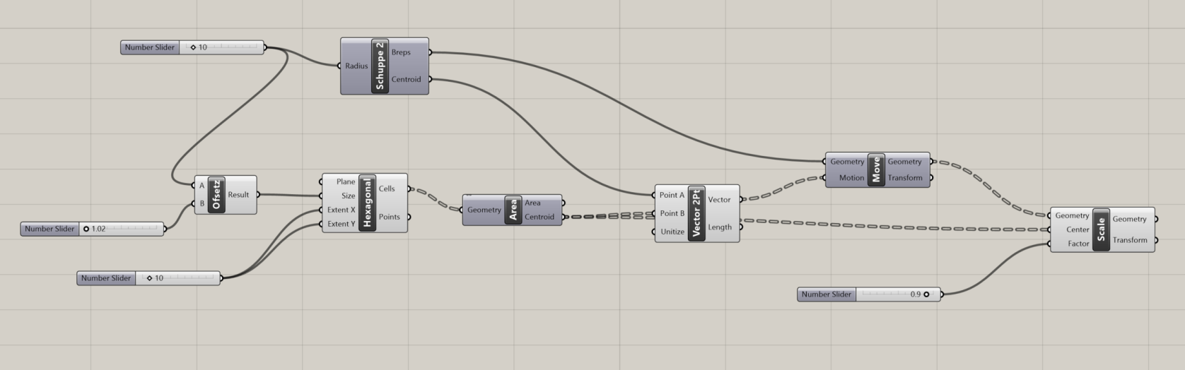
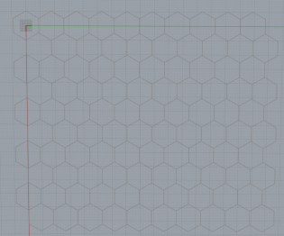
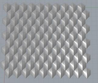
Next, I created a 10 × 10 hexagonal grid using the Hexagonal component in Grasshopper. I used the Area component to calculate the centroid of each hexagonal cell.
With Vector 2Pt, I calculated the vectors from the original scale's centroid to the centre of each grid cell. I then used Move to position a copy of my scale at each of these points.
Finally, I used the Scale component with a factor of 0.9 to make each scale slightly smaller while keeping it centred within its grid cell. This created a small gap between the individual scales.
Experimenting with Scale Variations
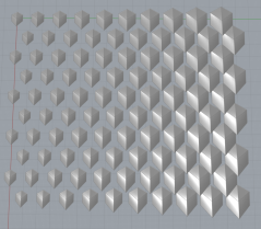
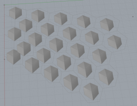
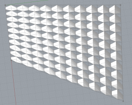
Next, I experimented with changing the size and position of the individual scales. I wanted to create a more organic arrangement, with smaller and larger scales that would distort the regular hexagonal pattern.
I tested different approaches and created three variations. Each produced a different arrangement, but none of them matched exactly what I had in mind. I wanted the scales to vary in size and overlap naturally, while still forming a connected pattern.
3D Printing
After experimenting with different variations, I decided to continue with the regular scale arrangement and prepared the model for 3D printing.
For this, I used our Bambu Lab X1 Carbon 3D printer and Bambu Studio to prepare the print file.
Transferring a Model from Grasshopper to Rhino (Bake)
- Make sure your model is finished in Grasshopper and the desired geometry is displayed correctly.
- Right-click on the final geometry component (e.g.
Brep,Mesh, orGeometry). - Select
Bake...from the context menu. - In the dialog box, choose the desired Rhino layer and confirm with
OK. - The geometry is now available as an independent object in Rhino.
- If necessary, disable the Grasshopper preview to avoid displaying the geometry twice.
Note: Changes made in Grasshopper after baking will not automatically update the Rhino object. If you modify your design, you need to bake the geometry again.
Exporting the Model as an STL File in Rhino
- Switch to the Rhino window.
- Go to
File → Properties → Unitsand make sure the units are set to millimeters (mm). - Check that your model has the correct dimensions.
- Make sure your model is a closed solid suitable for 3D printing. Open surfaces may need to be thickened or closed before exporting.
- Select the geometry you want to export.
- Go to
File → Export Selected.... - Choose
Stereolithography (*.stl)as the file format and enter a file name. - If the mesh settings dialog appears, you can use a tolerance of approximately
0.05–0.1 mmas a starting point. - Select
Binaryinstead ofASCIIand confirm the export.
Your model is now saved as an STL file.
Note: STL files contain only the surface geometry of your model. They do not store materials, colors, or reliable unit information.
Opening the STL File in Bambu Studio
- Open Bambu Studio.
- Switch to the
Preparetab. - Select the correct printer profile in the upper-left corner, for example
Bambu Lab X1 Carbon 0.4 nozzle. - Select the build plate you are using, for example
Textured PEI Plate. - Drag and drop your STL file onto the virtual build plate. Alternatively, import it using
File → Importor theAddbutton. - Your model will now appear in the workspace. Check that the displayed dimensions are correct before continuing.
Open-source slicing software for preparing, configuring and managing 3D prints, including print settings, supports and material profiles.
3D Printer
Machine Bambu Lab X1 Carbon
Company Bambu Lab
Build Volume 256 × 256 × 256 mm
Input Format STL, 3MF (via Bambu Studio)
Type FDM 3D Printer
Preparing the 3D Print in Bambu Studio
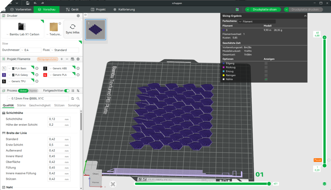
I prepared my scale design for 3D printing in Bambu Studio using the standard print settings. After importing the model, I sliced it to generate the individual print layers.
Since I wanted to place the fabric onto the print bed after the first layer, I needed to add a pause to the printing process. To do this, I selected the corresponding layer in the layer preview on the right side, right-clicked and chose "Add Pause".
During my first test, I selected layer 1, assuming the printer would pause after completing this layer. However, I discovered that the pause was inserted before the selected layer, meaning the printer stopped before printing anything.
To correct this, I moved the pause to layer 2. This way, the printer would complete the first layer and pause before starting the second layer, allowing me to position the fabric over the printed structures.
After adjusting the pause position, I sliced the model again and sent the print job to the Bambu Lab X1 Carbon.
Printing onto Mesh Fabric
The printer completed the first layer as planned and then paused. I placed my mesh fabric onto the print bed and secured it with magnets to keep it in position.
This turned out to be more difficult than expected because the printer's fan kept blowing the lightweight fabric away while I was trying to position it. After several attempts, I managed to secure the mesh and resumed the print.
Unfortunately, the printer got stuck and did not continue printing, so I had to restart the print job. For the next attempt, I started the print directly from the printer instead of my computer.
During a later attempt, I noticed something important about the pause function. When starting the print from my computer, I also needed to end the pause from the computer. Otherwise, the printer would get stuck instead of continuing.
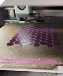
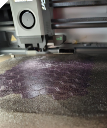
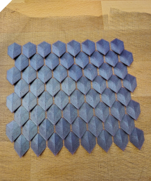
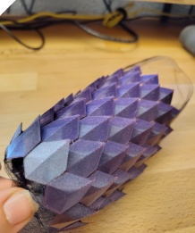
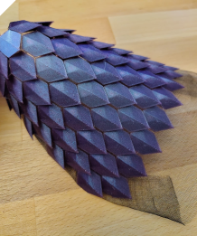
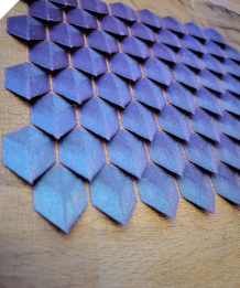
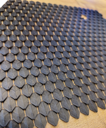
I alsoe print a version with smaler scales do see the dirfence.
06 Mathematical Patterns on Stretched Textile
Fibonacci Spiral
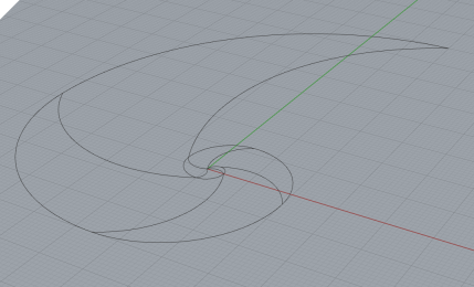
When I started exploring Grasshopper, I asked myself what I actually wanted to try. A spiral sounded like a good idea. And since the Fibonacci spiral is based on a mathematical sequence, I thought it would be an interesting starting point. How difficult could it be to calculate a few numbers and turn them into a curve?
Well, it turned out to be much more complicated than I expected.
First, I needed some kind of loop to generate the Fibonacci sequence, but Grasshopper does not have a conventional loop component by default. Then I had to figure out how to select and arrange the correct points to construct my spiral. Every time I thought I had solved one problem, another appeared.
What started as a small experiment turned into a much longer challenge. At some points, I was really close to giving up. But I wanted to understand how it worked rather than just use a finished definition.
After spending so much time developing my Fibonacci spiral in Grasshopper, I wanted to turn it into a physical object using 3D printing. To make the structure resemble a snail shell, I added connecting lines across the spiral. I did this by selecting the corresponding start and end points of the individual curve segments and connecting them with additional curves. This created a shell-like pattern within the spiral.
Sunflower Petal Structure
After experimenting with the Fibonacci spiral, I wanted to explore another mathematical pattern found in nature. This time, I chose a sunflower. I was interested in recreating both the petals and the arrangement of seeds in the centre of the flower.
Seeds The interesting thing about sunflowers is that their seeds are not arranged randomly. They follow a mathematical pattern called phyllotaxis, which describes how leaves, seeds and other plant structures are arranged during growth.
In a sunflower, each new seed is positioned at an angle of approximately 137.5° relative to the previous one. This angle is known as the golden angle and is closely related to the golden ratio and the Fibonacci sequence. Because the angle is an irrational fraction of a full circle, the seeds do not simply line up in straight radial rows. Instead, they form the characteristic interlocking spirals that can be observed in sunflower heads.
To recreate this in Grasshopper, I used a numerical series to generate the seed indices. From these values, I calculated the corresponding angle and distance from the centre. Using sine and cosine, I could convert these values into X and Y coordinates and generate a point for each seed.
The advantage of creating this parametrically is that I can experiment with the different values. Changing the number of seeds or the spacing factor changes the size and density of the pattern. Changing the angle even slightly produces a noticeably different arrangement.
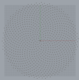
For the flower pattern, I first only had the seed positions as a point cloud. The next question was what kind of geometry these points should become. Since the distribution of the points was already very suitable for a Voronoi structure, I used the Grasshopper Voronoi function to generate cells based on the seed positions.
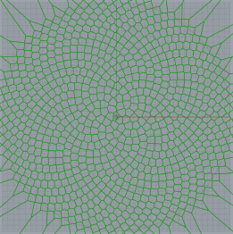
This created a pattern of irregular polygonal elements, which I found visually much more interesting than simply using the points themselves. To make the result even more dynamic, I scaled the individual cells according to their distance from the centre. The closer an element was to the midpoint, the smaller I made it. This created a stronger visual hierarchy and emphasised the centre of the flower.
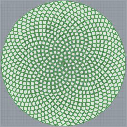
To turn the flat pattern into a three-dimensional object, I then used the centre point of each Voronoi cell and moved it upwards in the Z direction. Based on these lifted points, I created small spikes for each element, so that the surface gained a more sculptural and organic appearance.
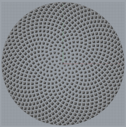
During export, however, I ran into a problem. When I saved the geometry as an OBJ file as I had done before, some layers or surfaces were missing. I first tried to repair the file in Meshmixer, but this changed the geometry too much and made the result look too smooth and rounded. After some experimentation, I switched to the STL file format instead, which preserved the geometry much better and worked more reliably for 3D printing.
Sunflower Petals
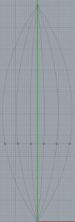
Next, I took a closer look at the shape of sunflower petals and tried to describe them using simple geometric elements. My idea was to create a petal from two fixed points connected by several curved lines. Instead of drawing each curve individually, I wanted to generate them parametrically in Grasshopper.
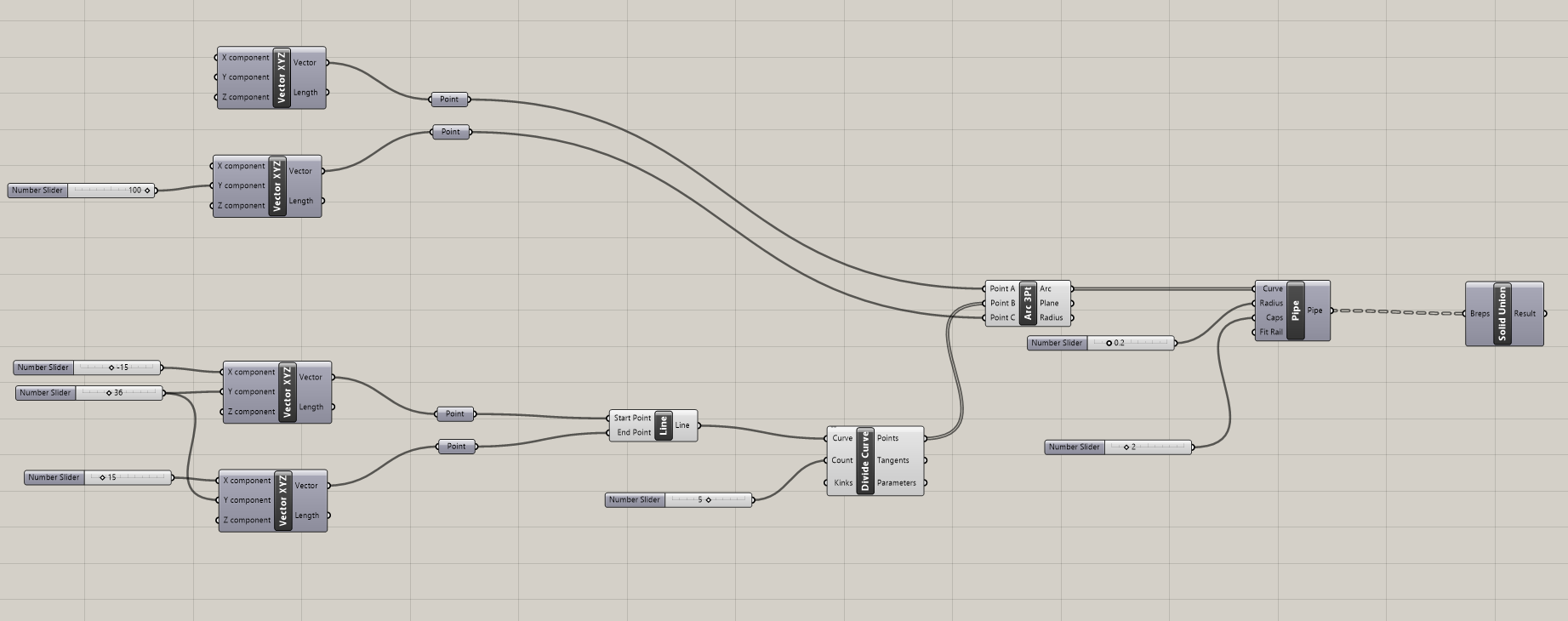
I started by creating two points using the Vector XYZ component. These define the beginning and end of the petal, and the distance between them determines its length.
To control the curvature, I created two additional points, one on each side of the petal. I connected these points with a Line component and used Divide Curve to divide the line into equally spaced points. The number of divisions can be adjusted with a slider, allowing me to control how many curved lines are generated.
Next, I connected everything to the Arc 3Pt component. The two fixed points define the ends of each arc, while the points from Divide Curve serve as the third points that determine the curvature. This generates several arcs that all start and end at the same positions but bend differently in between. Together, they create the shape of a sunflower petal.
The main adjustable parameters are the petal length, the width defined by the two side points, the position of the line between them and the number of divisions. By changing these values, I can experiment with different petal shapes without having to reconstruct the geometry.
Preparing the Printing Paths - GCODE generateor
My first approach was to turn the curves into pipes in Grasshopper and export the geometry for 3D printing. However, I kept running into problems with the slicer. Some parts of the lines were considered too thin, while others were too thick, and I was not happy with the resulting toolpaths.
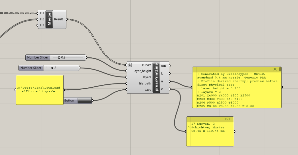
This made me wonder whether it would be possible to generate G-code directly in Grasshopper instead of relying on the slicer. This is where a Python script came into the game.
I started by taking an existing G-code file for a simple calibration cube that I had sliced for our Prusa MK4. I removed all the commands responsible for printing the cube itself, leaving only the basic structure and commands required for a standard print job.
Next, I considered which parameters I wanted to control directly in Grasshopper. I decided on the layer height, the number of layers and, of course, the curves that define the printing paths.
With some help from ChatGPT, I developed a Python script that takes my list of curves as an input and converts them into G-code commands. I also added two additional inputs to specify the file location and filename. By clicking a button in Grasshopper, the generated G-code can be saved directly as a file.
One limitation I encountered is that the script currently cannot overwrite an existing file. Whenever I change the parameters or modify the curves, I have to choose a new filename before saving the updated G-code.
This approach gives me much more direct control over how my spiral is printed, without having to rely on the slicer to interpret the thickness of the individual lines.
Printing on Stretched Textile
The next step was to print my designs onto stretched fabric. The main challenge was keeping the fabric under tension and securely attached to the print bed throughout the printing process.
I started with the same magnets I had previously used to hold the mesh in place when printing my dragon scales. However, these magnets were too weak to keep the fabric properly stretched.
As an alternative, I tried adhesive tape. At first, this worked surprisingly well, and the fabric stayed in position. Unfortunately, as the print bed heated up, the adhesive began to loosen and the fabric lost its tension.
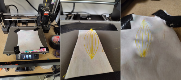
My next attempt was to use clips to hold the fabric in place. While these provided a stronger grip, they created a new problem: the clips were in the way when the print bed moved.
So I returned to the magnets, but this time I used larger, stronger ones. Since these magnets were also thicker, I first examined the printing path to identify safe positions where the print head would not collide with them.
After carefully positioning the magnets outside the printing area, this solution worked quite well. The fabric remained stretched and securely attached to the print bed, allowing me to continue printing my designs directly onto the textile.
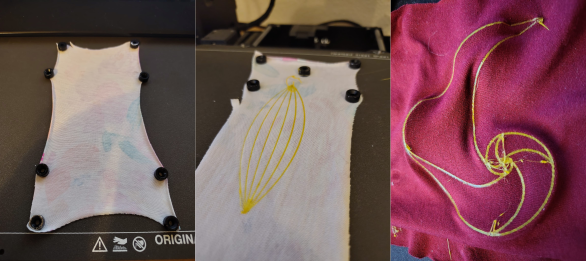
There is still some stringing visible in the print, and the order in which the individual lines are printed is not yet optimal. This is something I could improve by adjusting the sequence of the toolpaths in my Grasshopper definition. However, for these first experiments, I am quite happy with the results.
Results after Releasing the Textile
I am very happy with the results of the sunflower petals. After a few tests, I found that printing with two layers and stretching the fabric tightly enough produced the best results. The printed lines held their shape well and created the effect I was looking for.
I also discovered that it was important to let the print bed cool down completely before removing the fabric. When I waited until everything had cooled, I could remove the print without tearing or damaging the structure.
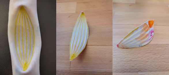
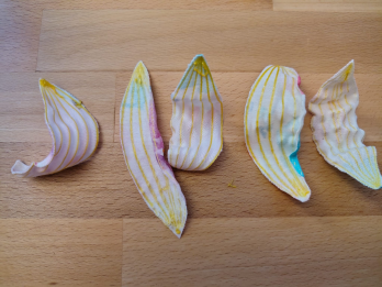
Here are my first five attempts at printing the sunflower petals. Each one had different problems. Some lines were printed too thin, others broke, and in some cases the magnets came loose during printing. These tests helped me identify the problems and gradually improve both the print settings and the way I attached the fabric to the print bed.
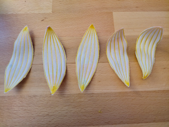
Here are my final sunflower petals. There are still some visible differences between them, as it is difficult to reproduce exactly the same tension in the fabric for each print. However, they all have a similar overall shape.
I actually find these small variations particularly interesting. After all, real flower petals are not completely identical either. Each one has its own slightly different shape, which gives the flower a more natural appearance. I like that this individuality is also reflected in my 3D-printed petals.
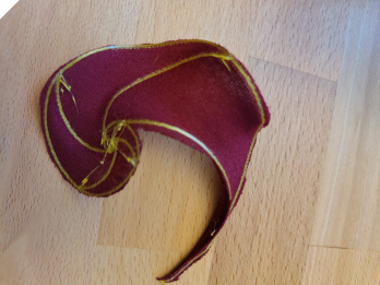
The spiral did deform after I released the tension in the fabric, so the basic principle worked. However, I have mixed feelings about the result. The shape looks interesting, but also a little random, without a clearly recognisable structure. It was useful to see how the printed spiral influenced the fabric, even though I am not entirely happy with the final appearance.
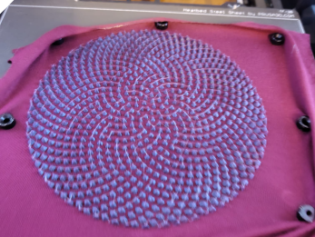
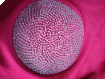
Finally, I tested my sunflower centre. In this experiment, printing onto stretched fabric did not produce the effect I had hoped for. In the first, small sample, I could see the fabric pulling together slightly after releasing the tension, but the overall effect was barely visible. I therefore printed a larger version to see whether increasing the size would make a difference.
Viewed from above, the larger sample is no longer completely round, suggesting that the fabric contracted more in some directions than others. However, this did not create a clearly visible three-dimensional deformation. For further experiments, I would like to try a different fabric or stretch it more firmly before printing to see how this changes the result.
I am not entirely satisfied with the final results. The tension in the fabric was probably too low, so the three-dimensional effect I had hoped for is barely visible after printing.
For future experiments, I think using a frame similar to an embroidery hoop could be an interesting solution. This would allow me to stretch the fabric more evenly and maintain the tension during printing.
Unfortunately, I ran out of time this week, so I could not test this approach yet. It is definitely something I would like to explore in a future experiment.
Final Flower
Here are some of the final results of my sunflower experiment. The images show the individual petals as well as the fully assembled flower. It is interesting to see how the different printed elements come together to form a complete flower, while each petal still has its own slightly individual shape.
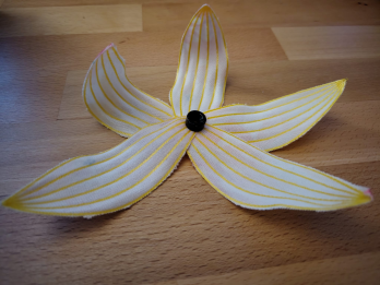
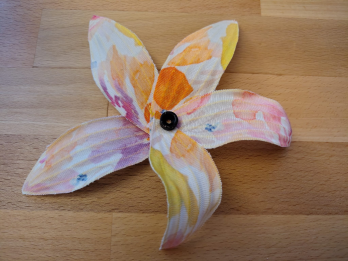
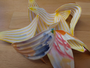
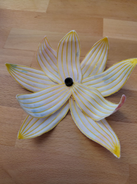
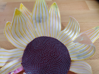
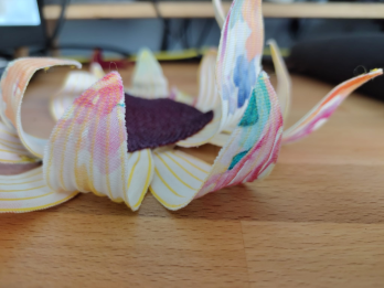
I left the larger sunflower centre on my desk and discovered an unexpected use for it: it makes a great fidget toy. Although it did not produce the deformation I had hoped for, it turned out to be very nice to play with. However, individual spikes gradually started coming loose from the fabric, so the attachment is not durable enough for repeated handling.
07 Fiels
User Objects
Grashopper
stl