Digital Bodies
00 Assignment
- Include inspiration and research on artists or projects working with the human body.
- Document the use of a 3D scanner and software to acquire a 3D model.
- Document the process of repairing and/or manipulating a 3D mesh and slicing it.
- Document the preparation of files for laser cutting.
- Learn how to use the laser cutter and document the workflow, including machine settings, material type and thickness.
- Upload the 3D file (STL / OBJ) and the 2D fabrication files (DXF / PDF).
- Build and/or assemble a mannequin or body parts.
- Extra: Create a stop-motion or step-by-step assembly process and upload a high-resolution picture of the finished mannequin.
01 Research & Inspiration
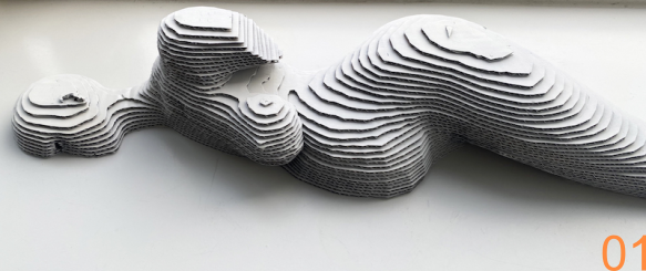
01 BODYWAVES – Alessia Pasquini
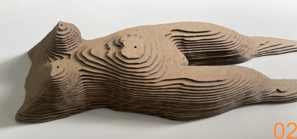
02 Digital Bodies – Flora Houldsworth
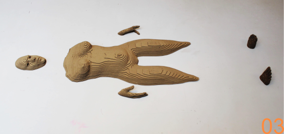
03 Digital Bodies – Sara Alvarez Vinagre
I really like the way these projects transform the human body into something between a sculpture, a landscape and an architectural surface. Instead of showing the body as a complete and separate object, parts of it seem to emerge from or disappear into another form. I especially like how the layered structures make the body look almost like topographic contour lines.
This reminds me a little of Te Fiti from Moana, where the landscape itself becomes a human figure. I really like this connection between body and landscape, because the human form is still recognizable without being shown in a completely realistic way.
My Plans for This Week
For this week, I had two ideas that would both make good use of the slicing technique.
The first idea is something I have wanted to make for our workshop for quite a while: holders for our ear defenders, as we usually call them, our “Mickey Mice”. I thought it would be fun if the holder was shaped like a 3D head. Simply 3D printing the whole head would be a little boring, so I would like to create it from stacked slices instead.
My second idea is a child-sized dresser form based on the current size of my older child. This would allow me to try on and check clothes while sewing without always needing the child to wear them. And staying still is also difficult at that age.
For this version, I would prefer to use cardboard. Children grow so quickly that it would not make much sense to build a very permanent version.
02 3D Scanning
For the scanning process, we used our Einstar Vega 3D scanner.
3D Scanner
Machine EinScan Pro HD
Company SHINING 3D
Output Format STL / OBJ / PLY
Type Structured Light
Scanning an existing object.
I had already used the scanner once or twice before Fabricademy, but I did not have much experience with it yet. One thing I already knew was that it is important to fully charge the scanner before starting. The battery can run out quite quickly, and this would be especially annoying in the middle of a scan.
Julia and I scanned each other. This way, both of us could practice using the scanner and both ended up with a scan of our own body.
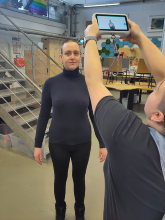
I needed two traings to get a scan I was happy with. During the first traing, I had my hair tied in a ponytail. The scanner had quite a lot of trouble detecting the hair correctly, so for the second scan I changed my hairstyle, which gave us a much better result.
After scanning, the file could be saved directly on the scanner. It was also possible to make some small adjustments on the device itself. However, working on the small screen was not very comfortable, so I preferred to continue editing the scan on the computer.
This led us to the slightly more difficult part:
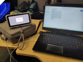
To transfer the scan to the computer, we first installed the Star Vision software and logged in.
Software for transferring, processing and editing 3D scan data from the EINSTAR VEGA.
The scanner can then be connected to the computer via USB cable. Inside the software, the stored scans can be selected and downloaded.
This was where our problems started.
The original cable of the scanner was missing, so we simply took the first suitable-looking cable we could find in the lab. At first, the scanner was not recognized correctly because the required driver had not been installed properly. We installed the driver manually and restarted the software.
Apparently, restarting the software is quite often the solution to technical problems.
After that, the scanner was finally connected and we selected the file we wanted to download. Since the scan file was quite large, the transfer took some time. Unfortunately, after a while the download stopped.
So we started it again.
And it stopped again.
During that afternoon, we tried several different USB cables, but the result was almost always the same: the download started normally and then failed before it was finished.
At some point, I finally managed to complete one download successfully, only to realize that I had selected the wrong scan.
After some searching and asking around, one of our colleagues was able to help us. He had a suitable USB cable that was also designed for data transfer. By then, however, the scanner battery was almost empty, so we first had to charge it again.
With a charged scanner and the correct data cable, the transfer finally worked without any problems. It was also faster than with the cables we had tried before.
Workflow
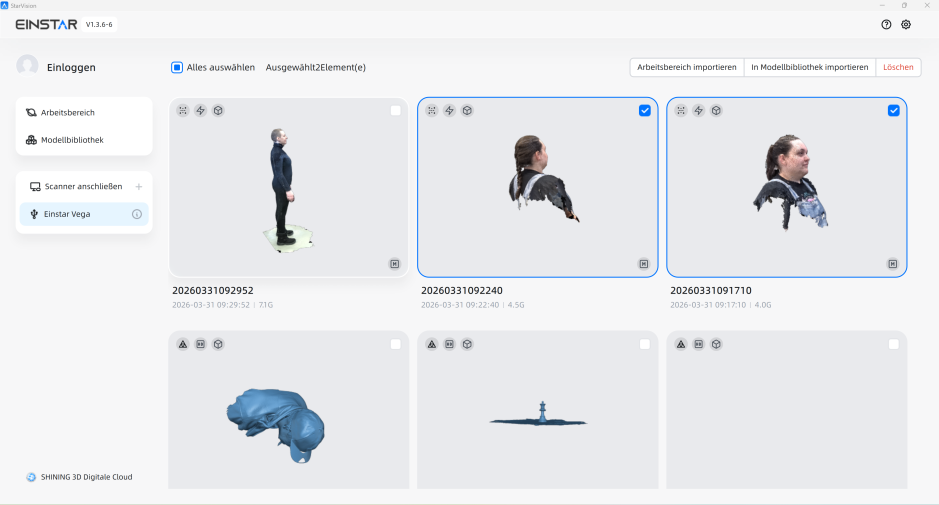
01 / Download
Select the correct files to download.
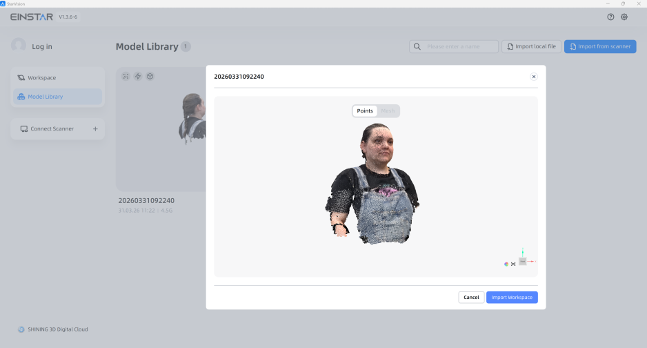
02 / Import Workspace
Assign the selected file to a new workspace.
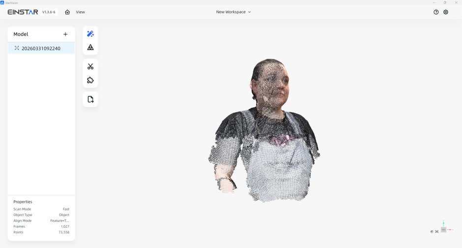
03 / Working Area
You can view the working area here.
03 Cleaning & Editing the 3D Model
For further processing, the software provides all the necessary tools to edit the 3D model. For example, transform, unwanted areas can be cut off, holes in the mesh can be closed, and multiple body scans can be combined into one model.
Workflow
01 / Cut
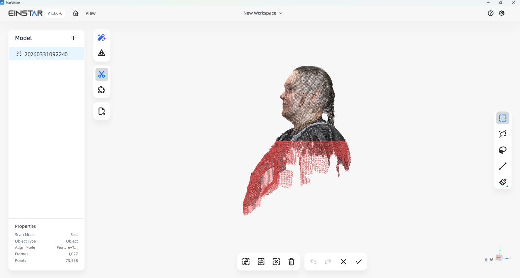
First, I created a straight cut at the bottom of the model so that the figure can stand properly later. To do this, I selected the scissors tool on the left side of the software. This opens a new menu where individual points or larger areas of the mesh can be selected and deleted. I positioned a cutting plane at the bottom of the figure. All points below the plane were highlighted in red. I then deleted the marked points to create a flat and even surface.
02 / Generate Mesh
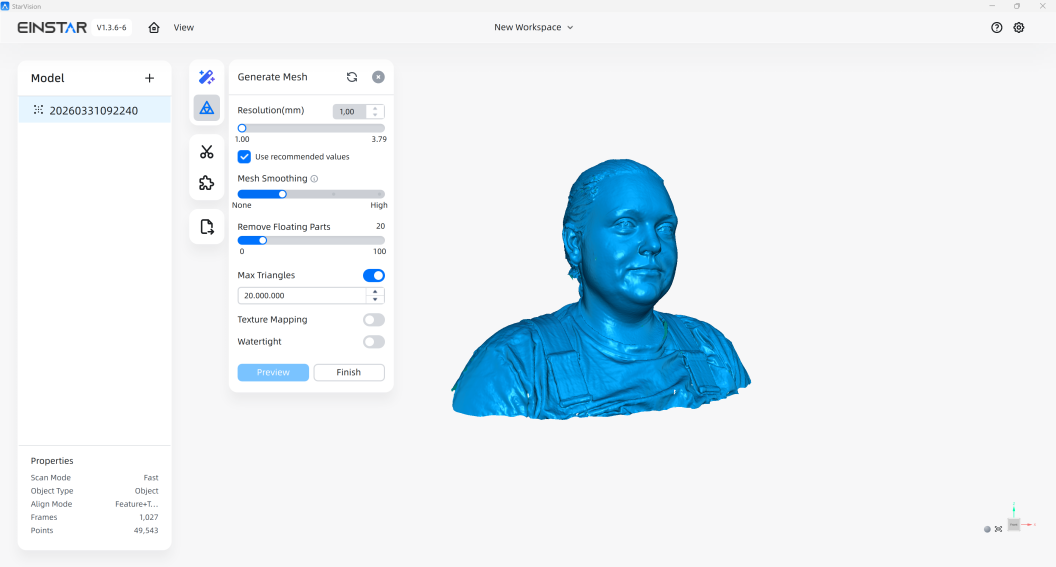
After cleaning the point cloud, I created the final mesh. For this step, several settings can be adjusted. First, I set the resolution to 1 mm. Another setting controls how smooth the final surface should be. The software can also remove small, disconnected parts that are floating around the main model. Here, it is possible to define the maximum size of these parts before they are automatically removed. Finally, I selected the maximum number of triangles for the mesh. A higher number of triangles creates a more detailed model, but it also increases the file size and the time needed for processing.
03 / Fill Holes
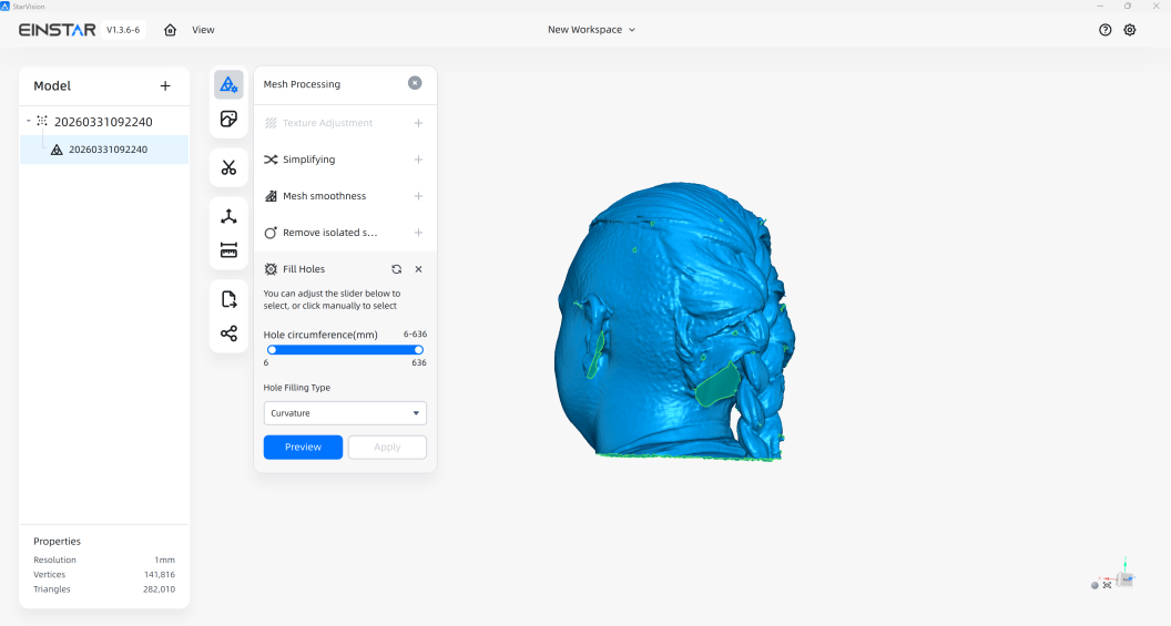
After creating the mesh, I made some additional corrections to obtain a closed model. There were a few small holes in the scanned surface, as well as the larger opening at the bottom that was created by the previous cut. The software allows me to define the minimum and maximum size of the holes that should be detected and closed. This makes it possible to repair only specific openings instead of changing the entire mesh. I could also choose between different methods for filling the holes, depending on how the missing surface should be reconstructed. After closing the remaining openings, I had a closed mesh that could be used for the next processing steps.
04 / Export
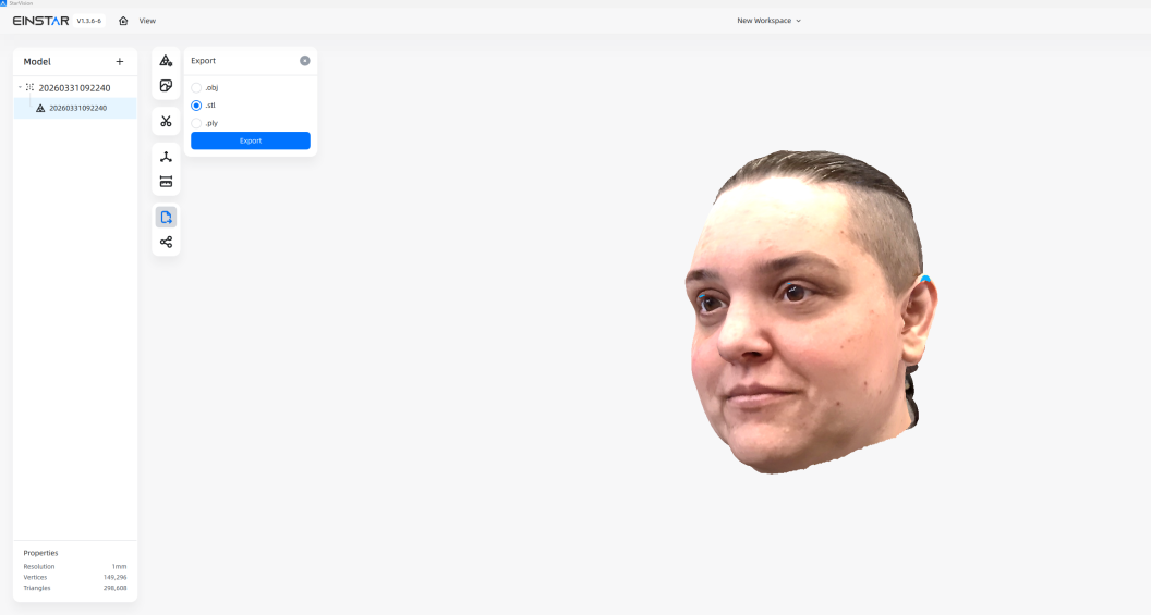
Now I could take a look at the finished mesh. The captured color information was also projected back onto the generated surface, which honestly made the result look a little creepy. After checking the final model, I exported the file. I chose the STL format because it contains the geometry I need for the next steps without additional information such as the color data.
04 Slicing it
Now that the final STL file was ready, I prepared the model for fabrication.
For this step, I used Slicer for Fusion 360. The software takes a 3D model and divides it into individual 2D parts that can later be cut from sheet material.
Software for slicing 3D models into 2D parts for fabrication and assembly.
Although Slicer for Fusion 360 is outdated and no longer actively developed, it is still available and works well for this purpose.
For this project, it provides the functions I need to divide the 3D model into individual 2D parts and prepare them for fabrication.
Workflow
01 / Import
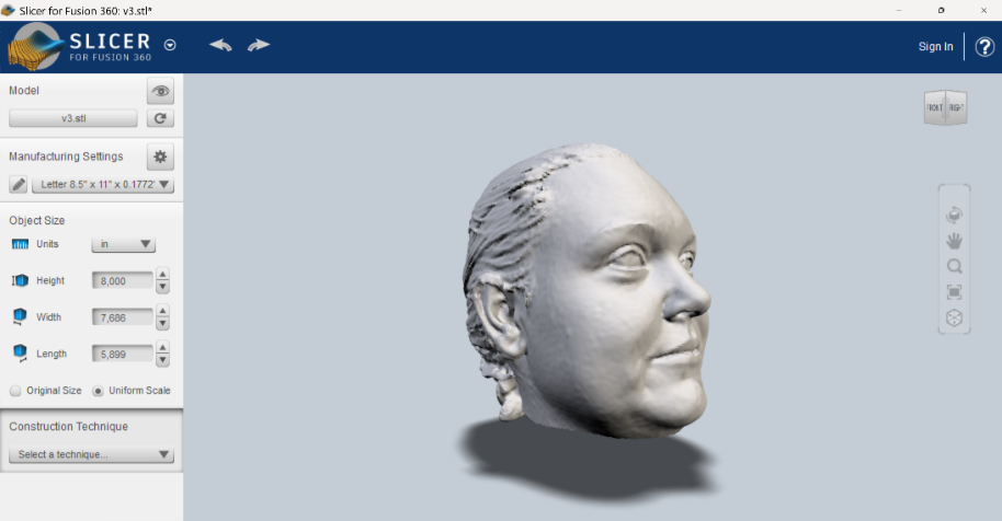
To import the model, I simply clicked Import in the top-left corner of the software and selected my STL file. The model was then loaded directly into Slicer for Fusion 360 and displayed in the workspace. That can sometimes take a moment.
02 / Manufacturing Settings
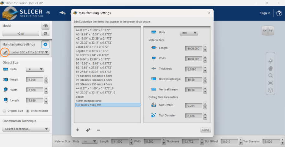
Next, I adjusted the settings for the material. To do this, I clicked the pencil icon next to Manufacturing Settings. This opens a new window where existing materials can be edited or a new material can be created. By clicking the + button at the bottom, I created my own material profile and entered the required dimensions. For my model, I used a wooden sheet with a size of 1000 × 1000 mm and a thickness of 8 mm. It's important that the material still needs to be selected.
03 / Troubleshooting
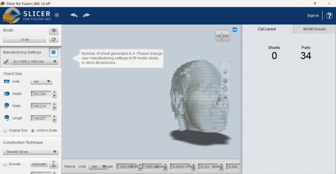
After setting up the material, Slicer initially did not generate any sheets for my model. I checked the material dimensions and the other settings several times and also restarted the software, but I could not find the cause of the problem. While testing different settings, I clicked Original Size. After that, the sheets were suddenly generated correctly. I could not determine exactly why this solved the problem, but resetting the model to its original size allowed me to continue with the slicing process.
04 / Slice Direction
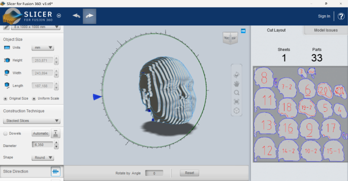
Next, I adjusted the Slice Direction. To do this, I selected the corresponding option in the menu on the left side. The direction of the slices can then be changed by rotating the controls around the model. I adjusted the orientation until the slices matched the direction I wanted for my final construction.
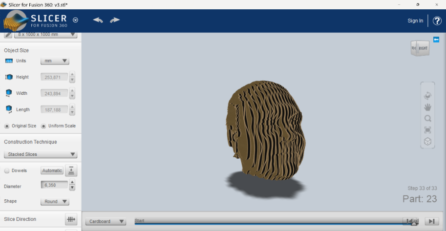
05 / Assembly Steps
Under Assembly Steps, I could preview how the model should be assembled. The software shows the construction process step by step and indicates the order in which the individual slices need to be placed on top of each other.
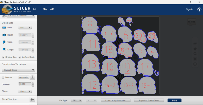
06 / Export
As the final step, I exported the generated cutting plans. To do this, I clicked Get Plans. The software then offers different file formats for the export. For my project, I chose PDF, as this format contains the generated 2D cutting plans and can be used for the next preparation steps before laser cutting.
Step 04.1 Modify it
Next, I opened the exported PDF in Inkscape because I was not completely happie with the generated cutting file.
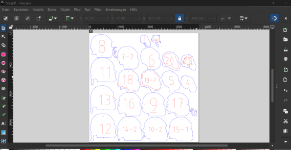
First, I removed all elements that I did not need for fabrication, such as the holes and labels.
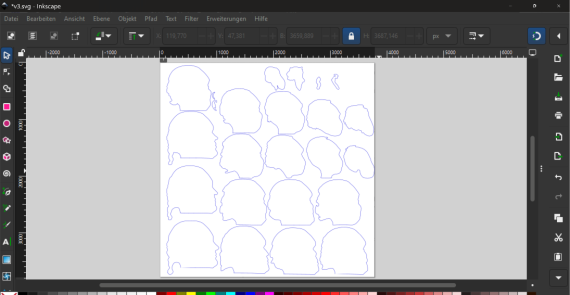
The outlines of the slices were made up of many individual line segments. To make them easier to edit, I combined these segments into continuous paths.

Finally, I adjusted some of the paths manually using the Node Tool. As shown in the example, I directly deleted or modified individual nodes to improve the shape of the cutting path.
05 Preparing the Files for Laser CNC
For the 3D head, I decided to use CNC milling instead of laser cutting. I wanted to avoid the dark, burnt edges that can occur when cutting wood with a laser, especially because the finished object will be handled regularly in the workshop.
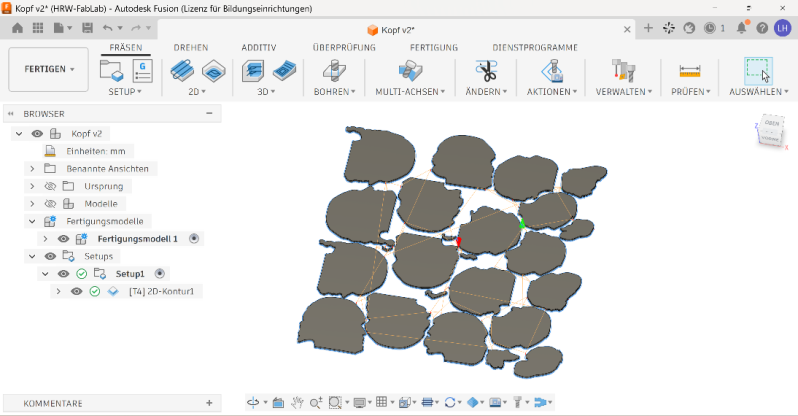
To create the CNC file, I used Autodesk Fusion 360. There, I could prepare the sliced parts, define the machining process and generate the toolpaths needed for milling.
3D CAD and manufacturing software for creating, editing and preparing models for fabrication.
Here is a short overview of how I prepared the cutting file for our CNC machine in Autodesk Fusion 360.
First, I created a new working area and imported the SVG file. Before continuing, I checked that the dimensions of the imported file were correct.
Next, I extruded the individual shapes to 8 mm, matching the thickness of my material.
After that, I switched to the Manufacture workspace. In the manufacturing model, I arranged the parts on a 1000 × 1000 mm sheet so that they fit onto the available material.
Then I created a Setup and defined the required cutting toolpath.
I also added tabs to the smaller parts. These small connections keep the pieces attached to the surrounding material during milling and prevent them from moving around or being thrown loose by the CNC machine.
06 CNC
When I wanted to start the CNC machine, the PC did not turn on. So before I could begin milling, I first had to troubleshoot the problem.
I checked all emergency stop buttons and the fuses, but everything seemed to be fine. The CNC machine itself started normally, only the PC remained off.
To solve the problem, I had to open the housing behind the screen and start the PC manually. This worked, but of course it took some additional time before I could actually start working with the CNC.
CNC Milling Machine
Machine Versatil 2500
Company EAS GmbH
Working Area 2500 × 1250 × 170 mm
Input Format G-code
Type CNC Milling Machine
Milling large parts from wood, plastics and non-ferrous metals.
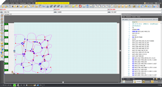
After solving the problem with the PC, I could finally start milling.
First, I placed the material on the machine bed and fixed it additionally with screws, because the vacuum table is sometimes not strong enough for smaller sheets.
Then I started the CNC software. The machine first performed the homing process to find its reference position.
After that, I opened my file, moved it to the correct position on the material, and was ready to start the milling process.
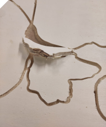
The milling process went quite well overall. Two of the parts came loose during milling, but luckily they stayed in a position where they did not interfere with the remaining milling process.
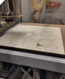
Here you can see the finished milled sheet. While removing the individual parts, I was not always sure whether a piece actually belonged to my model or was just leftover material from the milling process.
07 Genarete Body
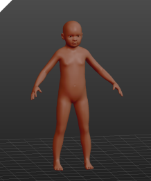
For my second project, I used MakeHuman to create a suitable human body model.
I started with one of the available human models and adjusted the body dimensions to approximately match the current size of my older child.
I deliberately made the model slightly larger. Since children grow quickly, this gives me a little more flexibility and should make the dress form usable for a longer period of time.
Open-source software for creating and customizing human 3D models.
08 Modyfy Body
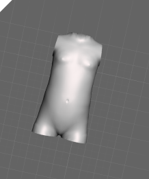
Next, I edited the model in
3D mesh editing software for cutting, repairing and preparing models for fabrication.
Since I only needed the torso, I opened the file and used the Plane Cut tool to remove the head, arms, and legs.
I then used Fill Holes to close the remaining openings. Finally, I exported the finished torso as an STL file.
09 Slicing it
I followed the same workflow as for the head and imported the STL file into Slicer for Fusion 360. This time, I used the torso model I had prepared in Meshmixer.
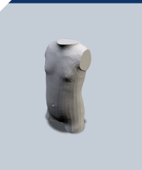
For the torso, I chose Interlocked Slices as the construction technique. This creates two intersecting sets of pieces that slot together to form the model.
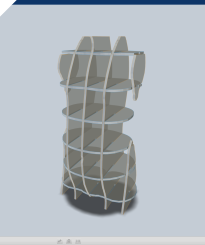
Next, I adjusted the slicing settings to adapt the construction to my torso model. The image shows the settings I used.
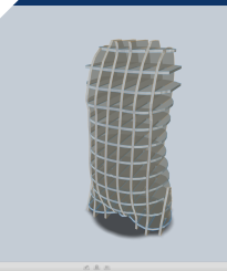
The preview shows the resulting structure and how the individual pieces fit together. The intersecting slices follow the shap of the torso while leaving open spaces between them.
10 Preparing the Files for Laser Cutting
Laser Cutter
Machine GS 100160 PR
Company GS Laser Systems
Working Area 1600 × 1000 mm
Software RDWorks
Input Format DXF
Cutting and engraving different materials with a CO₂ laser.
RDWorks is the software we use to prepare and send files to our laser cutter. I imported my file into the software, preferably as a DXF file.
In RDWorks, different settings can be assigned to the individual colors of the drawing. For my file, I set the red lines to only mark the surface, while the blue lines were set to cut through the material.
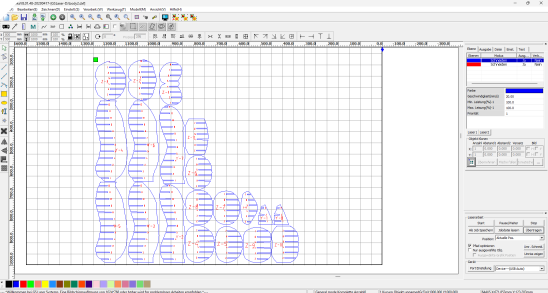
After checking the settings, the finished file can be transferred directly to the laser cutter.
Laser cutting software for preparing files, setting cutting parameters and controlling laser machines.
11 Laser Cutting
At first, I decided to use 12 mm cardboard because I wanted the model to be as stable as possible. I therefore started by testing whether this material could be cut properly with the laser.

During the first tests, I noticed that the autofocus of the laser was not calibrated correctly. So before continuing, I first adjusted the autofocus again.
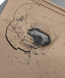
After a few more test cuts, I found settings that worked well, even though the cutting process was quite slow.
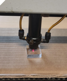
I then started cutting the final parts. The first section worked well, but after a while the cardboard started to burn. I immediately stopped the machine and removed the cardboard.
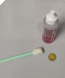
Because of the smoke and residue, I also had to clean the laser lens afterwards.
After the failed attempt with the 12 mm cardboard, I had to look for an alternative material. The only suitable cardboard we had available was 4 mm thick.
I opened the model again in Slicer for Fusion 360, changed the material thickness to 4 mm and generated the cutting files again.
Back at the laser cutter, I first made some test cuts to find suitable settings Like bevor.
Once I had found suitable settings, I sent the parts to the laser cutter in smaller batches. This made it easier to position them efficiently on the available cardboard sheets and use the material as well as possible.
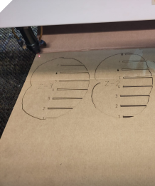
This time, everything worked as planned and all parts could be cut successfully.
12 Assembly
12.1 Head
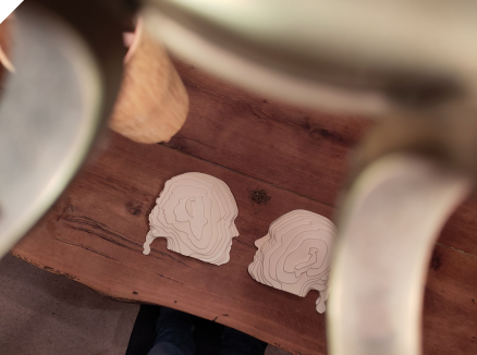
To record the assembly video, I attached my phone to our living room lamp so that I could film the process from above. I still had to adjust the setup a little because parts of the lamp were visible in the first recordings.
12.2 Body
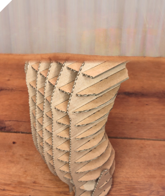
When I first put it together, I noticed that something wasn't right—the figure is too small; it's 10 cm shorter than I expected. I must have made a mistake somewhere between the two programs.
For the first video, I edited the footage myself using Canva.
For the second video, I wanted to experiment with AI-based image editing. I gave the AI the individual photos and asked it to create a more consistent background, because there were still some distracting objects visible in the room.
The first attempt did not work very well. The AI generated a slightly different background for almost every image, which made the stop-motion sequence look very inconsistent.
In the second attempt, the background was more consistent, but the AI accidentally removed parts of my model from some of the images.
This showed me that AI can be useful for image editing, but it is still difficult to keep the result consistent across a whole series of images.
13 Final Result
13.1 Head
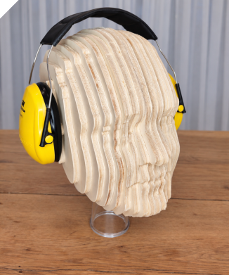
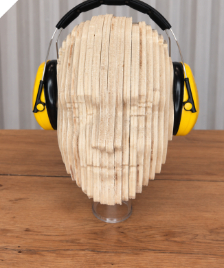
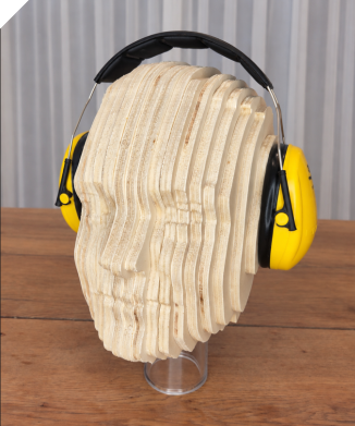
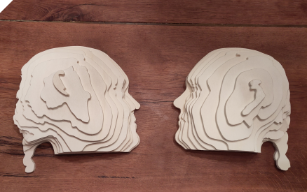
I am very happy with the final result of the headphone stand. But I also really like how it looked before assambly the two halves of the head face to each other. It gives the object a very interesting and almost sculptural appearance.
13.2 Body
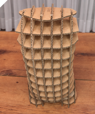
14 What I Learned
This week, I learned that even with good preparation, you should never fully rely on machines. Unexpected problems can always occur, so troubleshooting and flexibility are an important part of the process.
I also discovered how exciting it can be to create 3D objects in different ways instead of always using a 3D printer. Working with sliced models, CNC milling and laser cutting gave me a completely different perspective on how digital 3D models can be transformed into physical objects.
Another important lesson was that software and workflows do not always behave the same way on different computers. Something that works perfectly on one computer may suddenly cause problems on another, even when using the same files and programs.
I also underestimated how much time video editing can take. Even a short video can require a lot of preparation, selecting material, editing and adjusting small details.
Finally, I learned something about my own way of working. I often have many ideas at the same time and want to make everything as good as possible. This can quickly make a project much bigger than necessary. I need to reduce my perfectionism a little and focus more clearly on one project and one goal at a time. Not every idea has to be implemented immediately.
I also created some custom HTML elements for my documentation, for example cards to present the machines and software I used.
Another element I experimented with was a click-through image carousel. At first, this worked well and made it possible to show several process steps in a compact way. However, towards the end of the week I had several carousels on the same page, and in combination with Zensical they no longer worked reliably when navigating between pages.
After trying to fix the problem, I decided to remove the carousels again and display the images underneath each other instead. This solution is less interactive, but much more stable and makes sure that all images and process steps are always visible.
15 Files
Head
The original scan file is too large to share here, even when compressed. Therefore, only the edited version is available for download.

Body
99 Waste of the Week – Wood
With my final project in mind, where I want to explore how waste and old materials can be turned into something new, my instructor suggested that I start documenting the waste I create during each Fabricademy week. This also gives me the opportunity to look more closely at the waste streams we already have in our FabLab and to think about possible ways to reduce or reuse them.
This week, wood waste was especially relevant. It is currently one of the largest waste streams in our lab and also one of the materials that is most difficult for us to dispose of.
Wood scraps are created during many different processes, for example when using the CNC milling machine, laser cutter or saws. A large part of this waste consists of plywood, MDF or other composite wood materials. Because of glues and other additives, these materials cannot simply be burned.
Over time, we have collected a large amount of small wood pieces. Many of them are too small for regular projects, but at the same time still seem too useful to throw away. In addition, visitors often leave their leftover material in the FabLab after our Open Evenings.
So, for this week, my Waste of the Week is wood.