Soft Robotics
00 Assignment
- Research and document inspiration from artists, projects and scientific references exploring soft robotics, pneumatic actuators and shape-changing materials.
- Explore different materials and fabrication techniques, including silicone casting, 3D printing and heat-sealed textiles.
- Design and fabricate a pneumatic soft robotic actuator.
- Experiment with silicone casting to create a functional soft gripper.
- Explore inflatable textiles and their potential for shape-changing garments and wearable applications.
- Document the design process, materials, fabrication parameters and assembly steps.
- Test the prototypes and evaluate their movement, flexibility, airtightness and performance.
- Record observations, challenges, modifications and experimental results.
- Reflect on material consumption, waste and the sustainability of soft robotic systems.
01 Inspiration & Research
For this week’s research, I explored soft robotics projects using 3D-printed pneumatic actuators, cast silicone and heat-sealed inflatable materials. The examples show different ways of turning air pressure into movement, from bending robot legs and gripping fingers to flat structures that transform into three-dimensional shapes.
3D-printed pneumatic actuators
Dylan Drotman’s research portfolio presents three-chamber pneumatic actuators with bellows. The chambers can be controlled separately, allowing the actuator to move in different directions. The projects explore how actuator geometry influences movement and how these flexible structures can be used in robotic systems.
The 3D Printed Soft Quadruped demonstrates how soft pneumatic legs can be combined into a walking robot capable of navigating different types of terrain. It connects the design of individual actuators with their application in a complete robot.
01 3D Printed Soft Quadruped – Dylan Drotman
Silicone actuators and grippers
The PneuNets fabrication guide from the Soft Robotics Toolkit explains how to cast a pneumatic bending actuator. The chambered body and the bottom layer are made separately and then bonded together. A strain-limiting material embedded in the base restricts extension on one side, causing the actuator to bend when inflated. The illustrated process provides a practical reference for mould preparation, silicone casting and assembly.
02 PneuNets Fabrication Guide – Soft Robotics Toolkit
Another example is Ipek Kuscu’s Fabricademy project from 2026. She used a 3D-printed PLA mould to cast a pneumatic actuator in two-component RTV-2 silicone. After curing, the silicone parts were bonded together using freshly mixed silicone, and the air inlet was reinforced with an additional casting. Her documentation highlights practical challenges such as achieving thin walls, removing air bubbles and maintaining a level casting surface.
03 Soft Robotics: Silicone Casting – Ipek Kuscu
Heat-sealed inflatables and geometries
aeroMorph by MIT’s Tangible Media Group explores how heat-sealed chamber patterns transform flat materials into three-dimensional shapes when inflated. Saskia Helinska’s Unflatables investigates similar principles for wearables, with examples of expansion, bending and twisting. I found her Geometries section particularly useful for comparing flat patterns with their inflated forms and understanding how geometry and material constraints influence movement.
04 aeroMorph – MIT Tangible Media Group
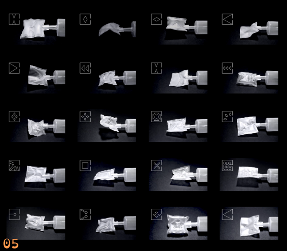
05 Unflatables: Geometries and Movements – Saskia Helinska
Inspiration
Based on this research, I want to reconstruct Drotman’s pneumatic robot leg in Grasshopper, cast a simple silicone gripper and experiment with heat-sealed wearable wings. For the wings, I want to test how different chamber layouts create movement, with the aim of developing a costume that changes shape when inflated.
Based on this research, I want to explore three approaches through my own experiments.
First, I want to reconstruct a pneumatic robot leg based on Drotman’s three-chamber bellows design. I have started developing the geometry parametrically in Grasshopper so that I can adjust its dimensions and prepare it for fabrication.
Second, I want to cast a simple silicone gripper. This will give me practical experience with mould making, casting, sealing and testing how the fingers bend when inflated.
Finally, I want to experiment with heat-sealed inflatable patterns for wearable wings. Inspired by aeroMorph and the geometries in Unflatables, I want to test different chamber layouts before developing a larger structure. My aim is to create clothing or a costume that changes shape when air enters it, with wings that unfold or move through pneumatic actuation.
Silicone-Cast Grippers
For this experiment, I decided to explore two different approaches to silicone-cast soft robotic grippers.
First, I want to reproduce one of the classic gripper designs provided during the course. This will help me understand how the air chambers work, how the silicone behaves when inflated, and how the geometry influences the gripping movement.
In addition, I want to develop my own gripper design. My goal is to experiment with different chamber shapes and arrangements to see how they affect the movement and flexibility of the gripper.
By comparing both designs, I hope to better understand the possibilities and limitations of silicone-based soft robotics.
02 Silicone-Cast Grippers
Step 01 — 3D Design & Download
For my silicone gripper experiments, I decided to try two different approaches: reproducing an existing design and developing my own.
For the first gripper, I downloaded one of the classic soft robotic gripper designs provided during the course.
Download: Soft Robotics Gripper Files
For the second gripper, I decided to create my own design using Autodesk Fusion 360.
I chose Fusion 360 instead of Grasshopper because I am still much more confident working with Fusion. Since I want to experiment with different shapes and ideas this week, I preferred using a tool I already know well.
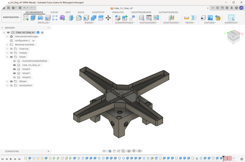
My own gripper design is intended to be integrated directly into my Morph3DBot system. The idea is to develop a modular soft robotic gripper that can be attached to any side of a Morph3DBot cube.
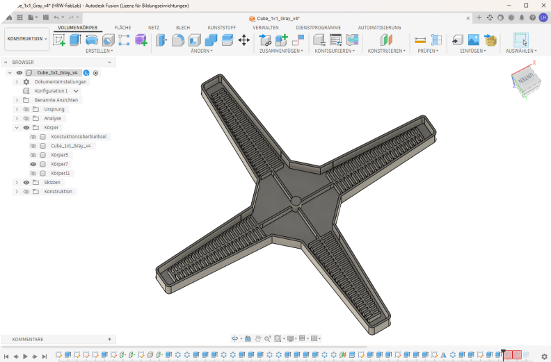
To achieve this, I used the existing internal geometry of the Morph3DBot cube as the starting point for my design. Based on this geometry, I developed the gripper and its connection so that it matches the cube's modular attachment system.
This way, the gripper can simply be plugged onto any side of a cube without requiring additional modifications to the existing Morph3DBot structure.
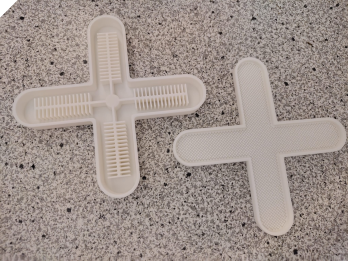
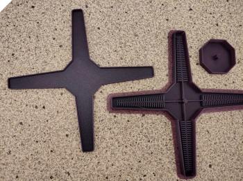
Step 02 — 3D Printing the Molds
Since I currently have a Prusa MK4 3D printer at home, I used it to print both gripper molds.
The downloaded gripper design consists of two separate parts that will later be glued together after casting.
My own gripper design consists of three parts, as I also want to integrate the silicone gripper into my existing Morph3DBot cube system. The additional part is needed to create the connection to the cube.
For both designs, I used the following settings:
- Printer: Prusa MK4
- Material: PLA
- Print Profile: 0.20 mm SPEED
- Brim: Enabled
During the first printing attempts, I noticed that the corners of the molds started to warp and lift from the print bed. Since the Prusa MK4 does not have an enclosed build chamber, maintaining a stable temperature around the printed parts can be more difficult.
To improve bed adhesion, I activated the brim setting in the slicer. This helped reduce the warping.
However, one of the molds still showed some lifting at the corners despite the brim. To prevent further deformation, I additionally secured the affected area with adhesive tape during printing.
Step 03 — Mixing the Silicone
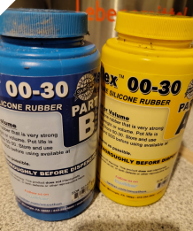
For casting the grippers, I used Ecoflex 00-30 from Smooth-On, a very soft and flexible two-component silicone.
The number 00-30 refers to the Shore 00 hardness scale, which is used to measure very soft materials. A lower number indicates a softer material, while a higher number means the cured silicone is firmer. Ecoflex 00-30 remains highly flexible and stretchable, making it suitable for inflatable soft robotic structures.
The silicone consists of two components, A and B, which must be mixed in a 1:1 ratio by weight or volume.
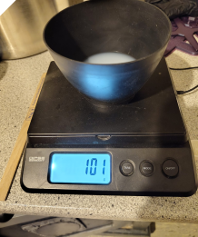
For my experiment, I prepared:
- Part A: 50 g
- Part B: 50 g
- Total: 100 g silicone mixture
I weighed both components using a digital scale and mixed them thoroughly until they were evenly combined.
According to the manufacturer, Ecoflex 00-30 has a working time of approximately 45 minutes and cures at room temperature in approximately 4 hours.
Step 04 — Removing Air Bubbles
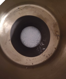
During the mixing process, air bubbles were introduced into the silicone. These bubbles can cause unwanted cavities or weak spots in the finished gripper. Since the gripper needs to be airtight to function properly, it is important to remove as many air bubbles as possible before casting.
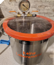
To degas the silicone, I used a vacuum pump and a vacuum chamber to create negative pressure. Under vacuum, the trapped air bubbles expand, rise to the surface and eventually burst.
I carried out this process before pouring the silicone into the molds. This is important because the silicone mixture expands significantly as the air bubbles rise. If I had degassed the silicone directly inside the molds, the expanding material could have overflowed.
Step 05 — Casting the Silicone
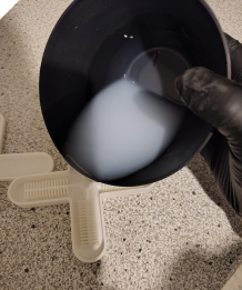
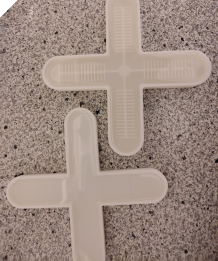
After removing the air bubbles, I carefully poured the silicone mixture into the prepared 3D-printed molds.
I poured the silicone slowly and evenly to avoid introducing new air bubbles into the material. I also made sure that the silicone could flow into all the small cavities and details of the molds.
Once the molds were filled, I left the silicone to cure at room temperature.
Step 06 — Curing the Silicone
After pouring the silicone into the molds, I left everything to cure overnight at room temperature.
Although Ecoflex 00-30 has a curing time of approximately 4 hours according to the manufacturer, I decided to leave the molds undisturbed overnight to make sure the silicone was fully cured before removing it.
Step 07 — Carefully Demolding the Silicone
The next morning, I carefully removed the cured silicone parts from their 3D-printed molds.
This step required some patience because the silicone is very soft and flexible. I had to find a good balance between gripping the material firmly enough to pull it out of the mold and being gentle enough to avoid damaging or tearing it.
I slowly loosened the silicone around the edges and carefully pulled it o
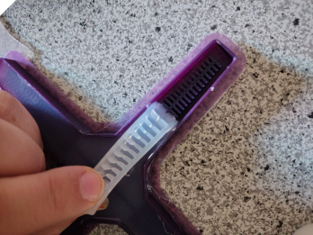
Step 08 — Bonding the Silicone Parts
After removing the silicone parts from their molds, I prepared a new batch of Ecoflex 00-30 using the same 1:1 mixing ratio as before.
I applied a thin layer of freshly mixed silicone to the contact surfaces of the individual parts to bond them together.
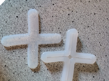
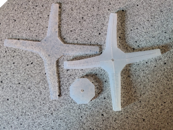
I then carefully aligned the parts and pressed them together, making sure that the air chambers and channels remained open and were not accidentally blocked by the additional silicone.
The goal was to create an airtight connection between the parts so that the grippers could later be inflated without air escaping.
Finally, I left the assembled grippers to cure again.
First Results — Testing the Grippers
Here are the first results of my silicone-cast grippers.
For the gripper based on the downloaded design, I carefully cut a small opening into the silicone to connect the air pump.
Unfortunately, I was not careful enough and cut too far into the material. This damaged the silicone wall and created an unwanted opening through which air can now escape.
As a result, the gripper cannot build up enough pressure to inflate properly.
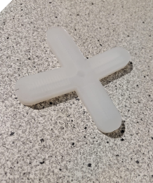
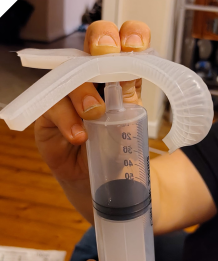
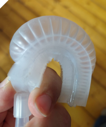
For my second, self-designed gripper, I encountered a different problem. One section of the silicone parts was not properly bonded, allowing air to escape through the connection.
However, when I temporarily closed the leaking area with my fingers, I could see that the gripper basically worked and responded to the air pressure.
Unfortunately, it bent in the wrong direction. This means that the design needs some adjustments to achieve the intended movement.
For my next iteration, I plan to make the bottom layer thicker and the upper layer thinner. The idea is that the thinner side will expand more under air pressure, while the thicker side will restrict expansion and guide the gripper into the desired bending direction.
Second Results — Testing the Grippers
The experiments turned out to be more difficult than expected. I identified several possible reasons why the silicone grippers did not work properly:
In some areas, the bonding layer did not seal the parts securely, allowing air to escape.
In other areas, I applied too much silicone, which blocked the air channels.
The gripper was left to cure on a surface that was not level, potentially resulting in uneven silicone thickness.
Only two of the four arms inflated initially. When I held those two closed, the other two inflated as well. This suggests that the arms required different pressures to inflate, possibly because of differences in wall thickness or partially blocked channels.
I then tested another version by bonding two arms together. When placed on the floor and inflated alternately, the structure crawled across the surface.
03 3D Printet Leg - Fail
During my research, I came across a really interesting soft robotic leg design that I immediately wanted to try out myself.
My goal was to understand how the geometry of the individual chambers influences the movement of the soft robotic leg and to explore how I could recreate and adapt this structure using parametric design.
Step 01 — Recreating a Design in Grasshopper
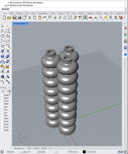
Using the available information and dimensions from the original project, I recreated a similar leg in Grasshopper.
Step 02 — 3D Printing with Flexible Resin
After recreating the soft robotic leg in Grasshopper, I wanted to try printing it directly using a flexible material instead of casting it in silicone.
For this experiment, I decided to test our Original Prusa SL1S SPEED.
Resin 3D Printer
Machine Original Prusa SL1S SPEED
Company Prusa Research
Build Volume 127 × 80 × 150 mm
Layer Height 0.01 – 0.1 mm
Materials UV-Curable Resin (405 nm)
Input Format STL / 3MF
Type SLA Resin 3D Printer
Printing detailed 3D objects using UV-curable resin. .
My idea was to use flexible resin to create the entire soft robotic structure in a single print, including the air chambers. This would eliminate the need for separate molds and the additional bonding steps required for silicone casting.
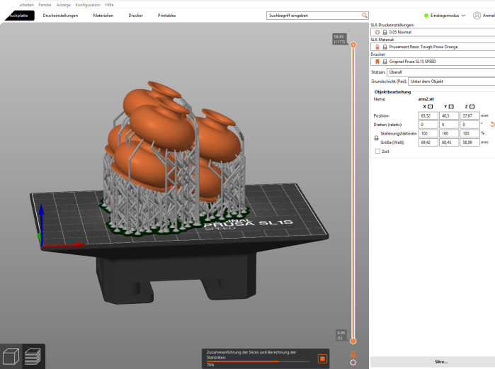
For the first test, I decided to print only a small section of the leg consisting of two chambers instead of the complete structure. This would allow me to test the material, print quality and functionality without using too much resin.
Step 03 — Printing and Post-Processing
Unlike FDM printing, resin printing requires additional safety precautions because uncured resin can be harmful when it comes into contact with the skin.
Before starting, I put on the appropriate protective equipment, including chemical-resistant gloves, safety glasses and protective clothing. It is also important to work in a well-ventilated area.
Starting the Print
First, I inserted the USB stick containing my sliced 3D model into the printer and selected the file.
The printer then displayed how much resin was needed for the print. I carefully poured the required amount into the resin tank and started the printing process.
After that, it was time to wait for the print to finish.
Removing and Cleaning the Print
Once the printing process was complete, I put on my protective equipment again and carefully removed the printed object from the build plate.
At this stage, the print was not yet ready to be handled without gloves because uncured resin was still present on its surface.
I placed the object into an isopropyl alcohol (IPA) bath for approximately 15 Minits to remove the remaining liquid resin.
After washing, I allowed the object to dry completely before placing it into a UV curing station for 15 Minits.
Once the object was completely washed, dried and cured, I could safely handle it without protective gloves.
Cleaning the Printer
The final step was cleaning the printer and all the equipment used during the process.
I carefully poured the remaining usable resin back into its container through a suitable filter, making sure that no cured particles were transferred back into the bottle.
I then cleaned the build plate, checked the resin tank for any remaining material and cleaned all the tools and surfaces that had come into contact with uncured resin.
First Results — Printing Attempts
The following two images show the results of my printing experiments. Unfortunately, none of the three attempts produced the desired result.
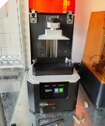
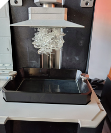
During the first attempt, the print failed because the orientation of the model created a large cross-sectional area. The printed layers adhered to the resin tank film instead of remaining attached to the build plate.
For the second attempt, I changed the orientation of the model to reduce the printing area per layer. Unfortunately, this attempt also failed.
I tried a third time with further adjustments, but once again, the result was not successful.
At this point, I decided to stop the experiment. Resin printing is quite time-consuming, especially because removing the prints, cleaning the equipment and preparing the printer for the next attempt require several additional steps.
Since I also wanted to complete my other projects during this week, I unfortunately did not have enough time to continue troubleshooting.
Although I was not able to produce a functional soft robotic leg, the experiment gave me a better understanding of the challenges of resin printing, particularly regarding model orientation, adhesion and the additional time required for post-processing.
04 Inflatebal Wings
For my third experiment, I wanted to create two inflatable wings for a costume by welding layers of plastic film together. The idea was to create air chambers that could be inflated and deflated to make the wings move.
But before designing the actual wings, I first needed to figure out how to join the available materials together and create airtight connections.
There are several ways to weld or heat-seal plastic films. I tested three different methods to find out which one would work best for my project.
Variant 1 – Iron-On Vinyl
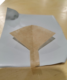
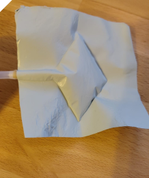
For my first attempt, I used iron-on vinyl (T-shirt transfer vinyl). The idea was to iron two layers together while placing baking paper between them in the areas where I wanted to create air chambers.
For this initial test, I cut both the vinyl and the baking paper by hand.
After my first test, I quickly realized that a single layer of baking paper was not enough, as the vinyl also stuck to the paper. I therefore had to use two layers of baking paper to prevent the air chamber from sticking together.
Although this method worked in principle, the resulting material was too stiff and not flexible enough for my inflatable wings. I therefore decided to explore other methods.
Variant 2 – Heat-Sealable Film
For my second attempt, I used a heat-sealable material (TPu - Beschichtet, verschweisbar) that I had specifically purchased for this experiment.
Again, I cut both the film and the baking paper into the desired shapes by hand using scissors.
After an initial test, I discovered that the material only bonded to itself and did not stick to the baking paper. This meant that a single layer of baking paper was enough to separate the two films and create an air chamber.
I first made a small test sample to see whether the method would work. The result was quite promising, and the layers bonded together well while leaving the intended air chamber open.
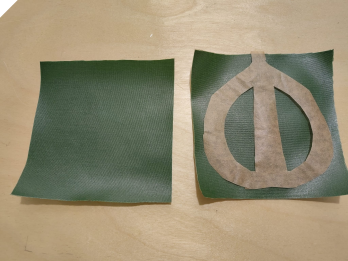
Encouraged by this result, I started a second, larger test to see whether the technique would also work on a bigger scale.
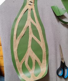
Unfortunately, even after ironing the material several times, I could not get the air chamber completely airtight. At first, I was unable to identify where the air was escaping.
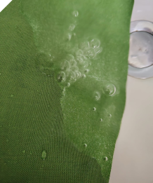
To find the leak, I submerged the sample in water and blew air into it. Surprisingly, I discovered that the air was escaping almost everywhere.
The material itself was not airtight. Only the areas where the two layers had been heat-welded together were sealed. In the areas where the baking paper had prevented the layers from bonding, air slowly escaped through the material.
This meant that although the welding technique worked, the material was not suitable for creating inflatable air chambers.
Variant 3 – Iron-On Vinyl with Silhouette Cameo 5 Heat Pen
For my third attempt, I returned to the iron-on vinyl from my first experiment, but this time I wanted to try a more precise method.
Instead of using an iron to heat the entire surface, I used the Silhouette Cameo 5 with its Heat Pen to weld the vinyl layers together only in specific areas.
Cutting Plotter
Machine Silhouette Cameo 5
Company Silhouette America
Cutting Area 305 × 305 mm (with cutting mat)
Maximum Material Thickness 3 mm
Materials Vinyl, Heat Transfer Vinyl, Paper, Cardstock
Software Silhouette Studio
Compatible Tools AutoBlade, Heat Pen (1 mm / 2.5 mm)
Type Desktop Cutting Plotter
Precision cutting of vinyl, heat transfer materials, paper, cardstock, and other thin materials. Supports additional tools for drawing, embossing, and applying heat-activated foil designs.
The idea was to create the outlines of the air chambers directly with the Heat Pen, leaving the inside of the chambers unbonded. This would allow me to create more detailed patterns without having to cut and insert baking paper between the layers.
Step 1 – Preparing the Design in Silhouette Studio
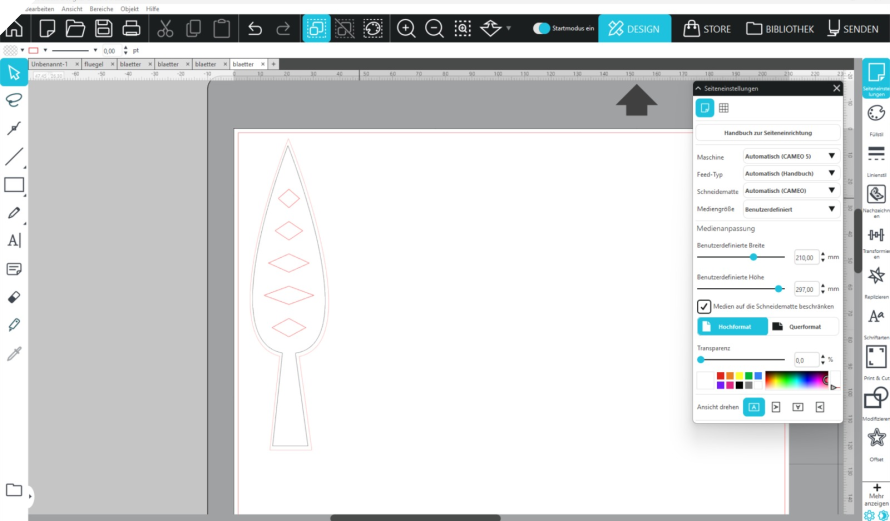
First, I imported my SVG file into Silhouette Studio and positioned the design on the virtual cutting mat. I adjusted its size and placement to match the material I wanted to use.
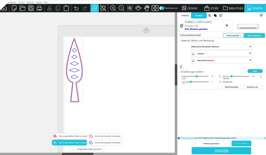
Step 2 – Adjusting the Heat Pen Settings
Next, I selected a material preset in Silhouette Studio that supports the Heat Pen. I chose Silhouette Faux Leather as the starting point.
Since I was using the Heat Pen for an experimental application, I had to adjust the settings manually. I performed several small tests to find a combination that worked best for bonding the vinyl layers.
After testing, I used the following settings:
- Force: 15
- Passes: 1
- Speed: 0.1
Step 3 – Preparing the Plotter
First, I placed the first layer of iron-on vinyl onto the cutting mat with the shiny side facing down.
Then, I placed a second layer of vinyl on top, this time with the shiny side facing up, so that the adhesive sides of both vinyl layers were touching each other.
I secured the second layer with adhesive tape to prevent the material from moving during the process.
Step 4 – Sending the Design to the Plotter
Next, I connected my computer to the Silhouette Cameo 5 via Bluetooth and sent the design from Silhouette Studio to the plotter.
My plan was to use two tools in sequence: first, the Heat Pen to bond the vinyl layers together along the selected lines, and then the cutting blade to cut out the final shape.
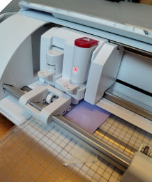
Before starting, the Heat Pen needed to warm up, which took some additional time.
Unfortunately, getting the process to work correctly was more complicated than expected. During my first attempts, the plotter performed the operations in the wrong order and started cutting before applying heat. In another attempt, it cut along the wrong lines.
It took several attempts and adjustments in Silhouette Studio to get the correct sequence and tool assignments.
One particularly frustrating part was that every time I cancelled a job, the Heat Pen had to heat up again before I could restart. This made the testing process quite time-consuming.
Eventually, I managed to get the plotter to perform both operations in the correct order: first heat-bonding the vinyl and then cutting the desired shape.
Testing Another Material – TPU-Coated Ripstop Nylon
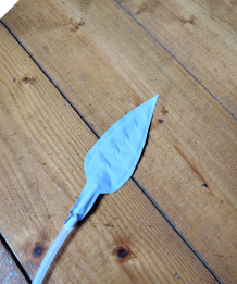
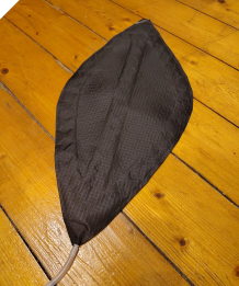
I also found another material to experiment with: ripstop nylon with a TPU coating on one side.
This material could be heat-welded using both a regular iron and a heat press, making it a promising alternative for creating inflatable structures.
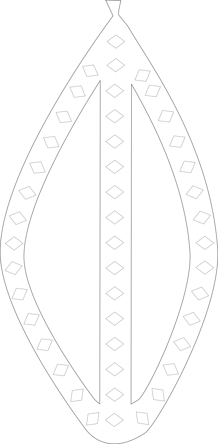
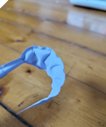
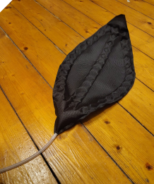
Here you can see my first wing design made with this material.

However, I was not completely satisfied with how the wings deformed when inflated. Therefore, I started working on a new wing shape inspired by the Saskia Helinska.
My goal was to improve the shape and achieve a more controlled deformation during inflation.

Preparing the Layered Wing Structure
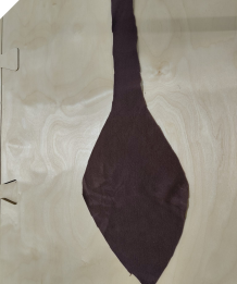
For my new wing design, I used a multilayer structure to control which areas would bond together and which would remain open to form inflatable air chambers.
I arranged the materials in the following order, from top to bottom:
- Fabric: The outer layer, which would later form the visible upper surface of the wing.
- Smaller TPU layer: Placed underneath the fabric to create the first bonding layer.
- Baking paper: Used to prevent the TPU layers from bonding in selected areas, creating the air chambers.
- Larger TPU layer: The bottom layer, which would bond to the smaller TPU layer wherever there was no baking paper in between.
The idea was to use heat to bond the layers together while keeping the areas separated by baking paper open for inflation.
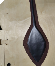
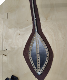
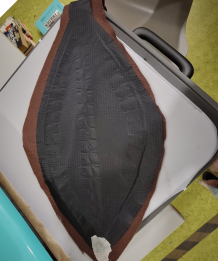
During the first test, the inflatable structure followed my intended shape very closely and deformed almost exactly as planned.
However, when I added the fabric layer, the result looked somewhat different. The additional material influenced how the structure deformed during inflation.
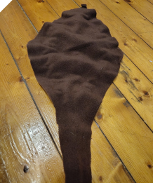
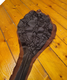
Making the Wings Child-Operated
To make the wings easy for a child to operate, I reused the air pumps from an old hat with moving ears.
I removed the pumps from the hat and connected them to the inflatable wings. This allows the child to inflate the wings manually by squeezing the pumps.
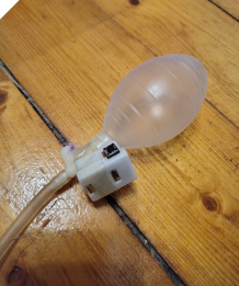
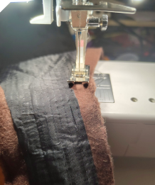
Finally, I sewed all the components together to create a wearable costume with interactive wings.
Although the wings do not flap as much as I originally imagined, a small fluttering movement is visible when the pumps are pressed and released.
08 Waste of the Week
This week, I produced quite a lot of waste due to the many experiments and failed attempts.
During the silicone gripper experiments, several attempts did not work as expected. Although I was able to reuse some of the silicone parts for other tests, quite a lot of leftover material remained. Unfortunately, cured silicone cannot simply be melted down and reused.
The inflatable experiments also generated a considerable amount of waste, including baking paper, backing films from the iron-on vinyl, and many failed vinyl samples.
While some of the smaller pieces could potentially be reused for future experiments, I am not yet sure what to do with most of the leftover vinyl and TPU-coated materials. Since these materials consist of different layers and coatings, recycling them is not straightforward.
Overall, this week showed me how much material can be consumed during prototyping, especially when experimenting with unfamiliar techniques. For future projects, I would like to reduce waste by starting with smaller test samples, optimizing the process before producing larger designs, and finding ways to reuse failed prototypes.