2. Digital bodies
This week let's explore different scanning tools , mesh tools , slicer for laser ....
Previous experiences with 3D scanning
During my fabricademy I was at the fablab "La Casemate" and the unique scan system was a Sense
I remember that I put it on a tripod then I scan myself or a rotative stool, so I didn't catch the top of my head abd I had to manipulate and close the mesh before printing a pen holder.
JMDPenHolderMadeDuringFabacademy2015
Scanning the Mannequin
First I would like to thanks Nina Gander from la HEAD "Haute école d'art et de design – Genève" who loan me a mannequin for that assignment.
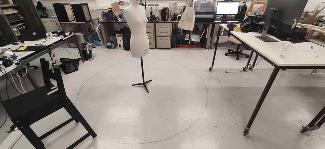
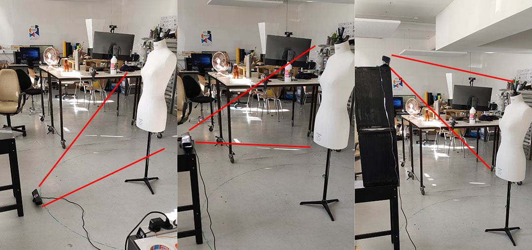
Let's prepare the space :
For scanning space and light are important. to be able to see the whole mannequin pictures or scan will be do done between 50 to 100 cm
SCAN3D software on android.
Basically you have to turn around your target and take picture when the indicator is green.
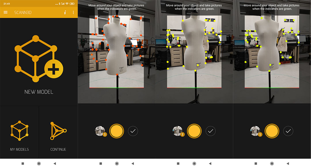
it takes time and honestly the result is not so good. also as it a fake free software so I decided to to swap to the same kind of process.
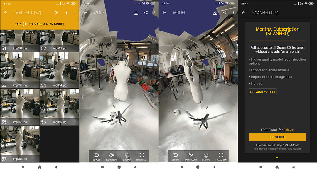
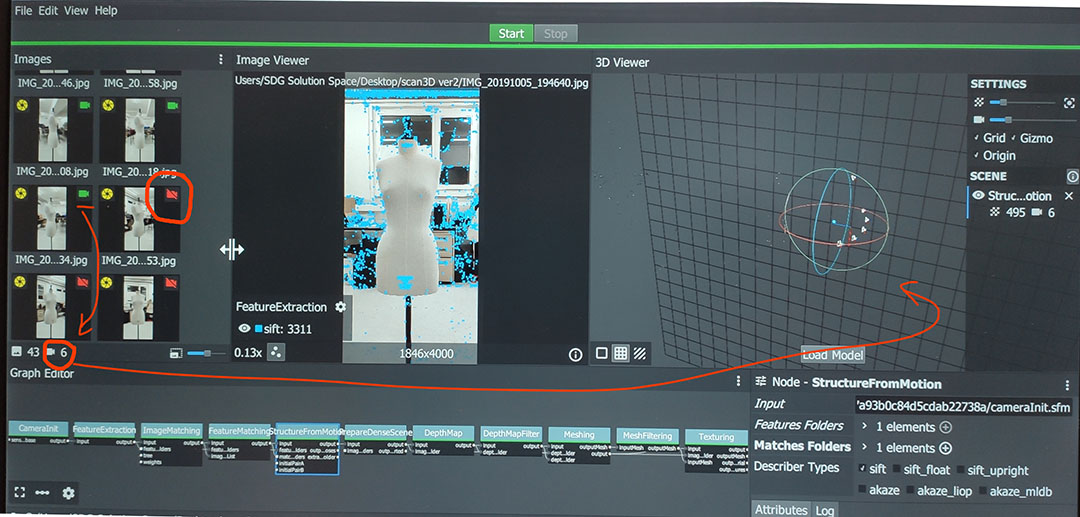
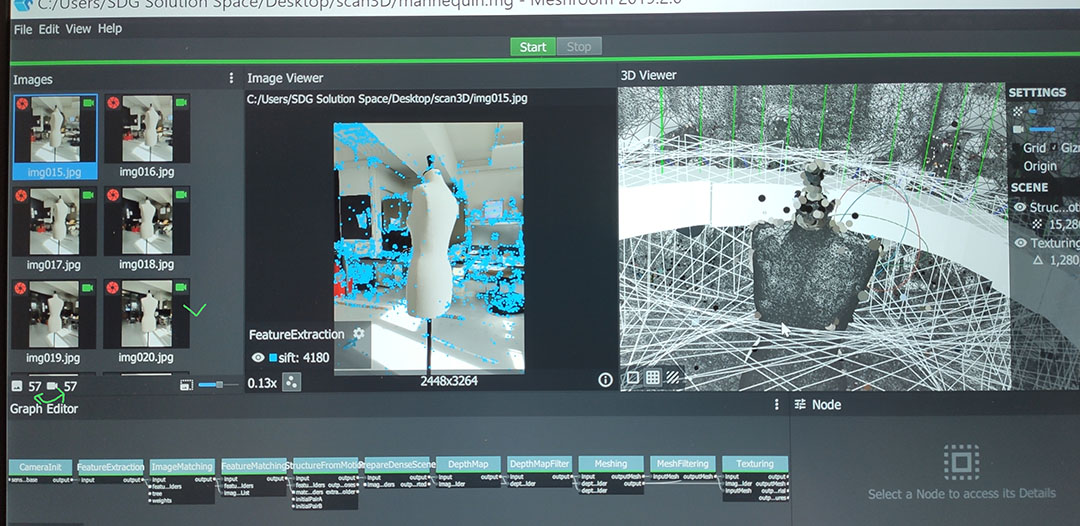
Meshroom: an open software
Meshroom is a photogrammetric software. from plenty of pictures taken around a subject it rebuild a mesh. but the difficulty is to take a good picture.
So I took plenty of pictures around the mannequin and unfortunatly only few of them were ok to be processed.
The previous software has some indicators to help you to take the perfect picture for scan so I decided to use the imageset from SCAN3D into Meshroom.
The result seems much better as all the pictures were ok even if without metadata.
I didn't really have time to use it seems really amazing. but using this software need to practice and I will ask Sebastien from Onl'fait to show me the tips and tricks de MeshRoom.
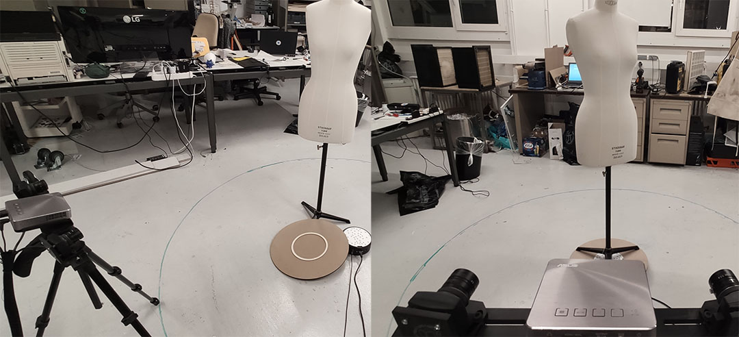
Scan In Box
The fablab purchased this scanner before I came, it's a precision tool , the precision is really high (75microns) which is nice for hard small part, but can't be used to scan body or flexible items because the sotware used to rebuild the mesh is really strict when you merge you different scans It use the Structured Light technology : one beamer, two camera and a rotative support for the object.
I laser cut a large disc to be able to put the mannequin on the rotative motor linked to the scanner.
Unfortanatly the laptop linked to this scanner was not in good shape when I was doing the calibration I had several new kind of Blue Screen with QRcode !
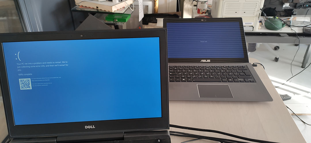
On the Left the ScanInABox Laptop, On the Right My own Laptop broken since last course, refusing load my profile..... After many try, I rage quit and decided to find another solution to get this scan done.
Scan with the kinect (for Xbox360) and using Kscan3D ver1.2
Last Year I built the Augmented reality Sandbox, so I practice a little bit the kinect and I have to say that it's a crazy tool also at his price, I bought it for 9€ with the power adaptor @ CashConverter.
Aaaahhhh easy system :
the mannequin can rotate on itself around a vertical axe, the idea is to set the position of the kinect, the software will take 20 shoots, 1 every 3sec with bip sound which help you to rotate a little bit the mannequin. when it's done you have 20 meshs and the software help to align and combine them. To be able to cover the full volume of the mannequin, you have to repeat the process with a lower and higher position of the kinect. then you will have 3 Mesh not closed, you have to manually align them and ask the software to combine more precisely to close at max the scanned volume.
For this scan I will make 20 scan for a rotation of the mannequin and I will do it 3 times from different elevations:
Note for Myself : need to find a real free software
When it's done, you can export your scan as .PLY . I will now use MeshMixer to clean Up the mesh , get rid of the holes and export it as an STL File
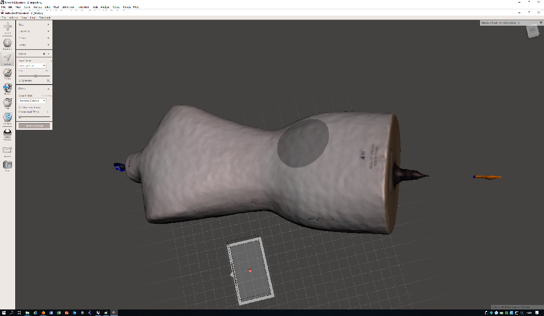
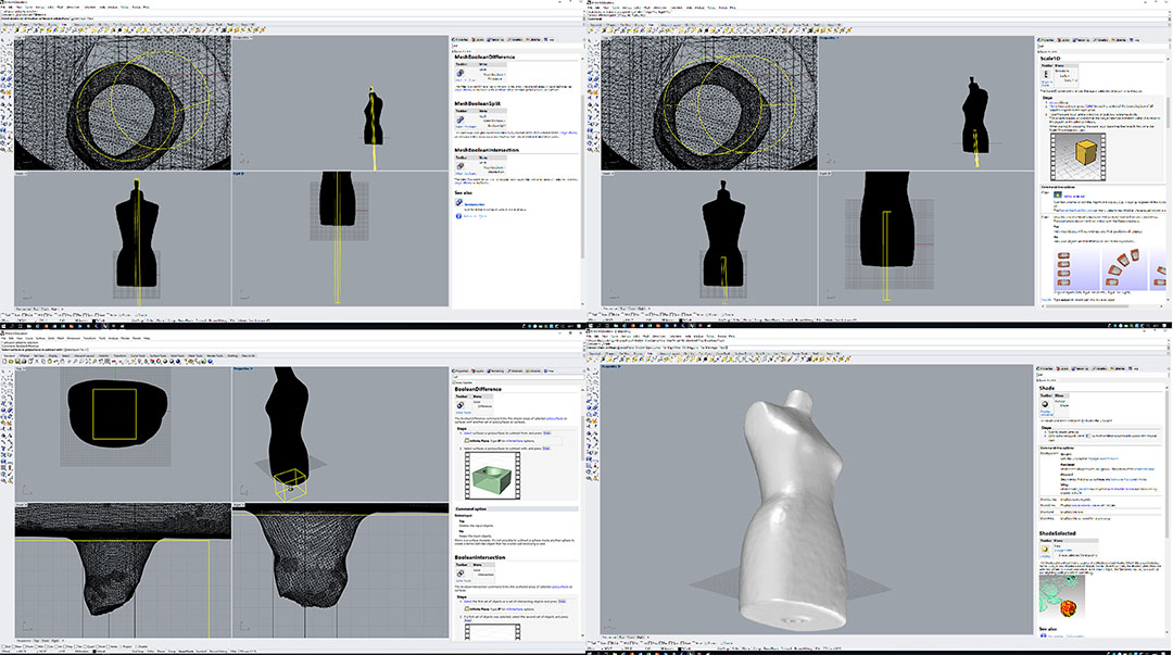
Then I saved it as STL file and continue the edition under Rhino to remove the 2 ends and create a hole in order to put a support in the future.
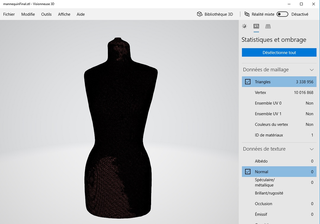
The final result is nice but really too big 167 Mb, >3.3M triangles, >10M Vertices
So the idea is to reduce the Mesh using Rhino : let's start with 85%
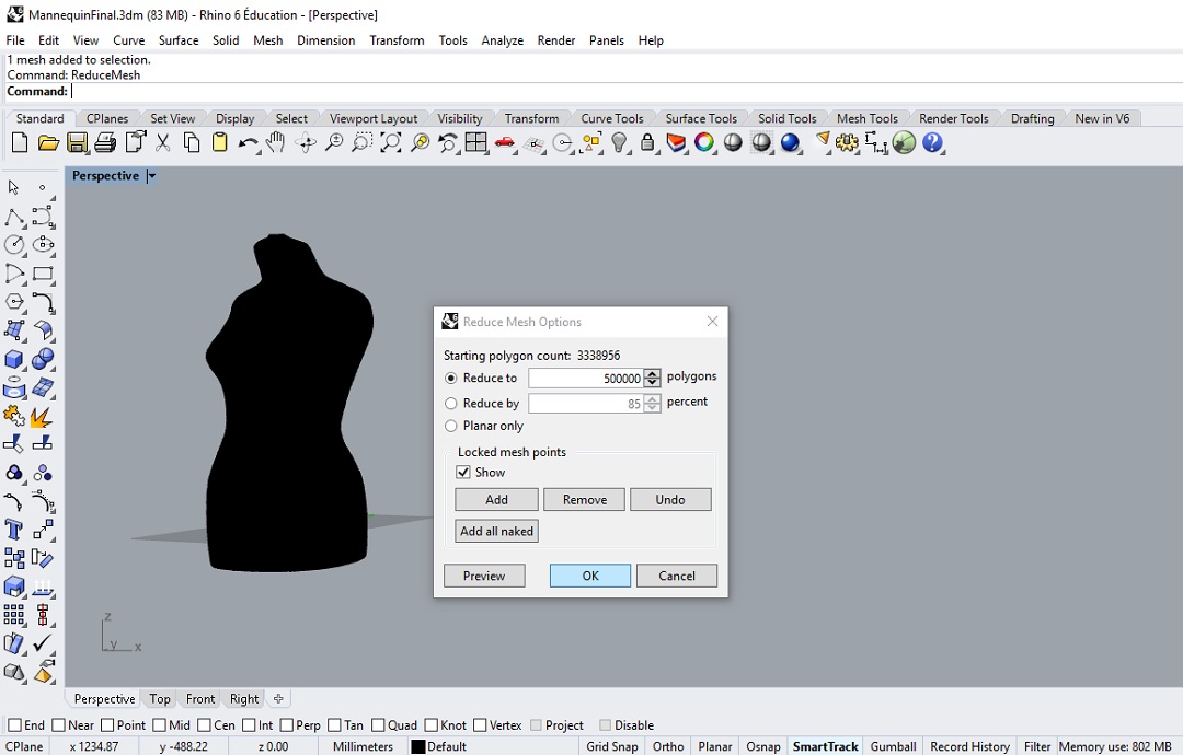
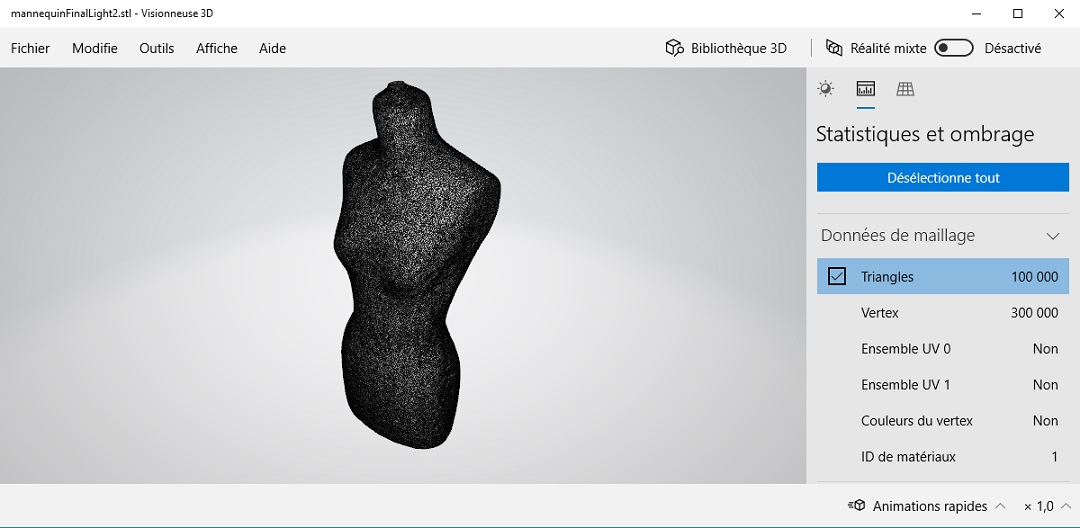
But it's not enough, the file is still about 25Mb so I set the number of faces to 100000 and less than 5MB
Slicing the Mesh
To pass from 3D to 2D+ I used SliceForFusion,
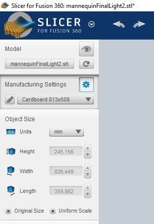
select the model : the stl file I just produced.
then I set the size of the sheet : here I choose the working sige of the laser cutter 813mm x 508mm and I also set the thickness of the cardboard 2.7mm , the unit used and I check the box original Size.
Then the software propose different methods for slicing the 3D volume:
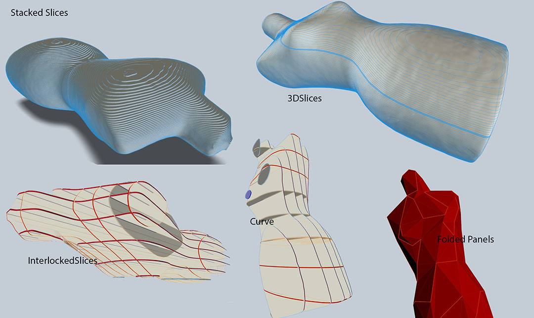
But the most appropriate for me is the radial one because I can set the axe to be the axe of the cylindrical hole I made
I decide to put 10 horizontal slices for 16 vertical
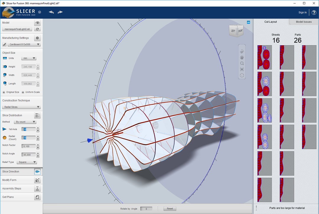
Unfortunately My Mesh is about 826mm high and the longest dimension of my sheet is 813mm so the software told me that "Parts are too large for the material" but as you can see is not good at all for placing cut on sheets. so I decided to download the result and create cut files by my own.
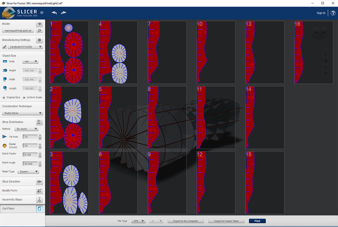
Also when you ask to export as EPS file the software create a zip file with all the sheets, but I have to review the positionning by rotating parts to fit in the space and to reduce the number of sheet necessary.
at the same time I should change the color to fit to the Trotec system but I decided to do it under the trotec material configuration.
Cutting with the Laser using Ai et TrotecDriver
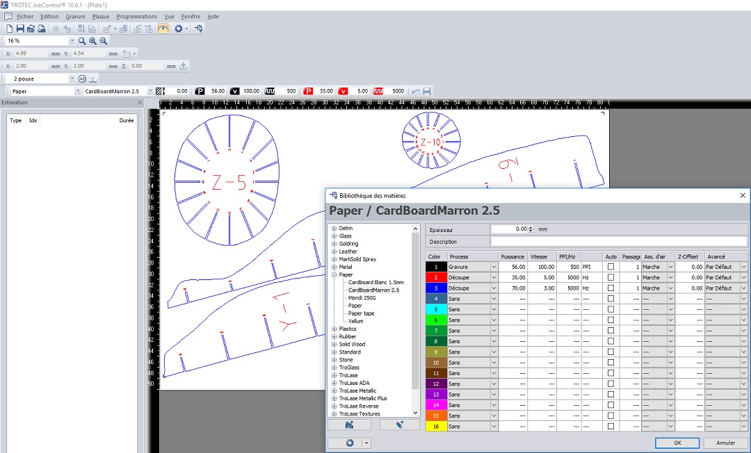
Trotec setting are usually like this : Black or any line with a thickness >0.01mm will engraved, when the thickness is 0.01mm then RGB red is cutting and you can define other color as you want.
Usually I use RGB blue 0000FF to cut with not enough power to pass trough the material (specifically with cardboard I use it as a folding line), but the slicer program is using RGB red FF0000 to engrave the number and the blue to cut.
so in the Trotec drive I redefine the parameters to cut on blue line and cut also on red line but with less power and more speed it will engrave the number at a better speed than engraving.
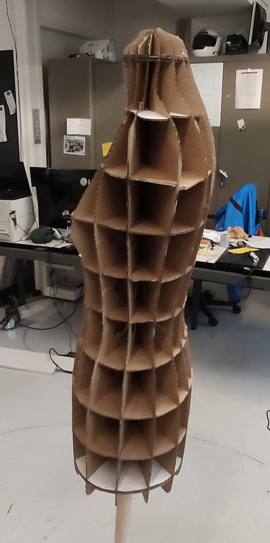
This video was made on the second cardboard mannequin . why a second one ? because the neck and the bottom were too fragile so I decided to re-enforced them by increasing the thickness of the cardboard on the 2 extremity.
Additionaly I would like to grow a mushroom in it, so to facilitate the propagation of the mycellium I added hole to each part.
also because every body has a different laser cutter with different working area size I prefer to share one big file with all the parts.
Result
NEXT STEP FILLING IT WITH Mycellium (see Week 6 Biofabricating)
I was thinking also doing it using legobrick with the help of tinkercad webpage
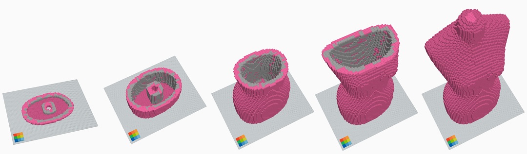
But It's definitly too much bricks !!