5. E-Textiles and Wearables I
This week Is dedicate to wearable.
At the beginning I will describe the different wearable componant that I will use and then I will create a Demo Pad using those componants.
EeonTex High-Conductivity Heater Fabric - NW170-PI-20

High-conductive heating fabrics are so hot right now! Literally! This non-woven fabric feels a little like felted paper but is filled with conductive material that can make the fabric emit heat when powered. Resistive heating fabrics safely deliver comfortable conductive and radiant heating at low voltage through thin, lightweight and flexible fabric. Unlike conventional resistive wire heaters, the whole surface of the fabric is conductive, providing more uniform and foolproof heating without the discomfort, weight and hazards of wires. It functions even if punctured, cut, spindled or mutliated!
According to EeonTex, this fabric is a conductive, nonwoven microfiber for use in e-textiles as well as electromagnetic and resistive heating applications. Each order comes with one sheet of 12"x13" inch / 30cm x 33cm fabric with a nominal 0.6mm thickness. This fabric is super versatile and perfect for anyone interested in wearables, cosplay, and e-textiles. Maybe even usable in scientific, crafting, or medical endeavours.
This fabric comes with a resistance of 20 ohms/square inch. We powered it up with some alligator clips and a 12V DC power plug and it heated up pretty fast! It isn't going to compare with your space heater, or boil water, but it does get warm.
Features
Filament Blend: Polyester/Nylon 6 (70/30) Power Density: up to 3.1 watts per square centimeter Coefficient of Variation: +/- 5% Sheet Resistivity: 20 Ohm/sq Sheet Size: 12"x13" (304.8 x 330.2mm) Thickness: 0.6mm Operating Temperatures: -50C to 250C Figure of Merit: 3 x 10³ Thermal Diffusivity: 1.3 x 10² per square centimeter per second Thermal Conductivity: 0.2 watts per meter per degree Kelvin Specific Heat Capacity: 0.4 joules per gram per degree Kelvin Web Bonding: 170 g/m2 Tensile Strength: > 450 N Elongation at Break: 40% Tear Resistance: 12 N
So if it warms up when the current pass through it, it means that we can use a strip as a potentiometer
image with multimeter
adafruit GEMMA M0
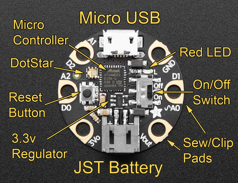
Description:
GEMMA M0 Setup
the Gemma M0 can be programmed using Arduino IDE but also in Python using CircuitPython.
I never user CircuitPython so it's for me a good opprotunity to try it:
The Gemma M0 I have got from fablab On'lfait was used under arduino IDE so I need to reset it:
1 Download the lastest version of CircuitPython for Gemma M0
2 Plug your Gemma into your computer using a known-good USB cable.
3 Double-click the small Reset button opposite the On/Off switch on your board. You will see the Dotstar RGB LED turn green.Note: The little LED next to the On/Off switch will be red - this is ok!
You will see a new disk drive appear called GEMMABOOT.
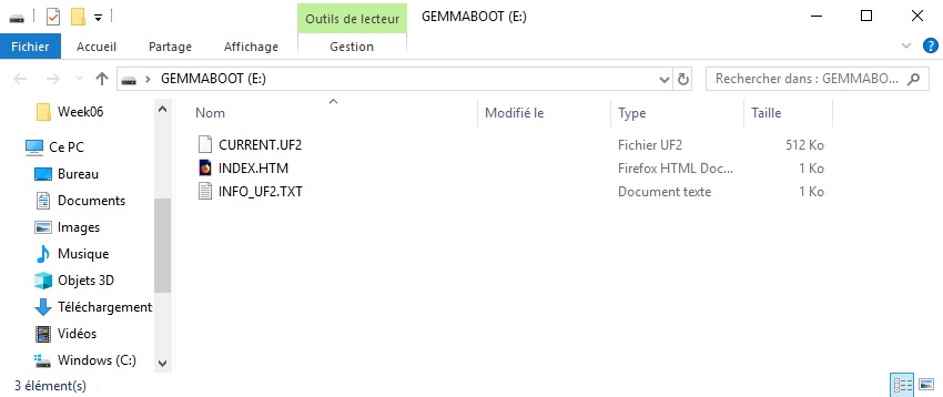
Drag the .uf2 file you download in step 1 to GEMMABOOT.
The red LED will flash. Then, the GEMMABOOT drive will disappear and a new disk drive called CIRCUITPY will appear.
That's it, you're done! :)
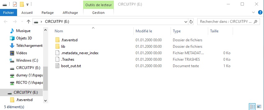
4 Download and install Gemma Default Zip
Open the zip file, select all files and folder except "Windows / Driver" and drged them to the CIRCUITPY drive. If it asks to replace anything, say yes.
Now the Gemma M0 is ready and run a demo program main.py
5 Install Mu Editor
Mu is a simple code editor that works with the Adafruit CircuitPython boards. It's written in Python and works on Windows, MacOS, Linux and Raspberry Pi. The serial console is built right in so you get immediate feedback from your board's serial output!
Download Mu from https://codewith.mu. Click the Download or Start Here links there for downloads and installation instructions. The website has a wealth of other information, including extensive tutorials and and how-to's.
The first time you start Mu, you will be prompted to select your 'mode' - you can always change your mind later. For now please select Adafruit!
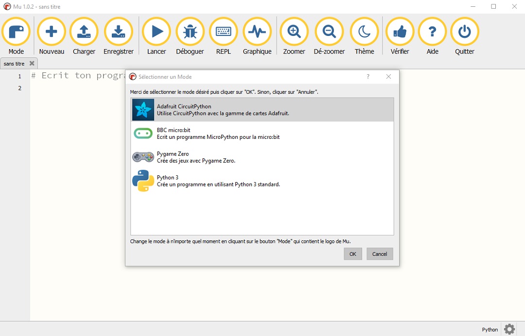
Now we are ready to code
project idea
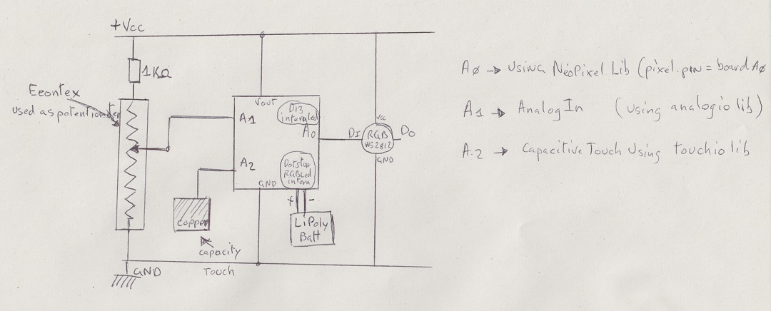
I will program the Gemma M0 as following
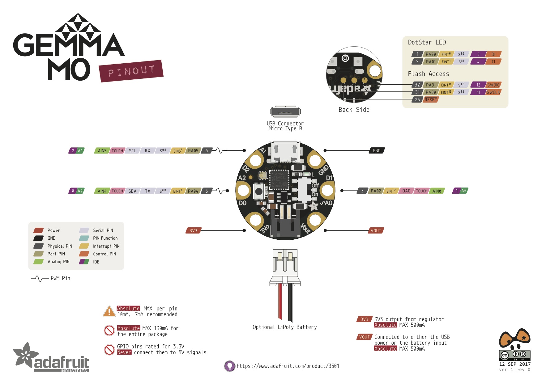
A2 as a capacitive touch sensor using a copper textile A1 as an Analog Input using the eoontex as a potentiomer to create value between 0..255 A0 as an Output to pilot a Flora RGB Smart NeoPixel
I will also use the Built in RGB DotStar LED
The idea is to set Red value then Green value then Blue value using eoontex and capacitive then lightup the RGB smart NEO pixel with the value.
At first time I will make a small program for each function to test it, Then I will put them together for the small project.
- AnalogInput & Eoontex
# CircuitPython AnalogIn Test
import time
import board
from analogio import AnalogIn

# A1 in mode Analog is linked to cursor on Eoontex which is connected between ground and vcc
analog_in = AnalogIn(board.A1)

# return value between 0..255
def get_voltage(pin):
    return (round((pin.value / 256)) - 1)


while True:

    print(get_voltage(analog_in))
    time.sleep(0.1)
- Capacitive Touch The following program light the internal REDLed when you you touch A2
import time
import board
from digitalio import DigitalInOut, Direction
from touchio import TouchIn

# Built in red LED
led = DigitalInOut(board.D13)
led.direction = Direction.OUTPUT

# Capacitive touch on A2
touch = TouchIn(board.A2)

while true:

# use A2 as capacitive touch to turn on internal LED
    if touch.value:
        led.value = touch.value
- Schematic
- FinalCode
import time
import board
import neopixel
from digitalio import DigitalInOut, Direction
from analogio import AnalogIn
from touchio import TouchIn
import adafruit_dotstar as dotstar


# external RGB led connected to A0
pixel_pin = board.A0
num_pixels = 1
pixels = neopixel.NeoPixel(pixel_pin, num_pixels, brightness=0.3, auto_write=False)
# One pixel connected internally!
dot = dotstar.DotStar(board.APA102_SCK, board.APA102_MOSI, 1, brightness=0.2)

# Built in red LED
led = DigitalInOut(board.D13)
led.direction = Direction.OUTPUT

# Analog input on A1
analog1in = AnalogIn(board.A1)

# Capacitive touch on A2
touch = TouchIn(board.A2)

# Helper to convert analog input to voltage
def getVal():
    Valpot = analog1in.value / 256
    if Valpot > 255:
        Valpot = 255
    if Valpot < 0:
        Valpot = 0
    Valpot = int(Valpot)
    return (Valpot)

ValR = 0
ValG = 0
ValB = 0

WHITE = (255, 255, 255)
RED = (255, 0, 0)
GREEN = (0, 255, 0)
BLUE = (0, 0, 255)
BLACK = (0, 0, 0)
Compteur = 0


dot[0] = WHITE
dot.show()

# MAIN LOOP
while True:

# print for debug
#   print("A1: ", getVal(), Compteur, ValR, ValG, ValB)

    # use A2 as capacitive touch to turn on internal LED
    if touch.value:
        print("A2 touched!", Compteur)
        Compteur = Compteur + 1
    led.value = touch.value

    while touch.value and Compteur == 1:
        dot[0] = RED
        dot.show()
        ValR = getVal()


    while touch.value and Compteur == 2:
        dot[0] = GREEN
        dot.show()
        ValG = getVal()

    while touch.value and Compteur == 3:
        dot[0] = BLUE
        dot.show()
        ValB = getVal()

    while touch.value and Compteur == 4:
        dot[0] = BLACK
        dot.show()
        pixels[0] = (ValR, ValG, ValB)
        pixels.show()


    if Compteur == 4:
        Compteur = 0
        ValR = 0
        ValG = 0
        ValB = 0