10. E-Textiles and Wearables II
This week the purpose is to create and test different type of accuator
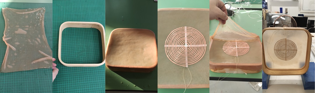
Speaker using Kombucha, copper and magnet:
Since the beginning of Fabricademy I have 2 boxes where I grew kombucha. In one of the boxes I decided to produce kombucha with a thickness about 4mm so it will be very thin when it's dry.
the idea is to put the copper between to layer of Kombucha before it dry.
I used a wood frame coming from a broken IKEA clock found in the street. I applied the first layer of Kombucha with a little bit of tension, then let it dry. After 4 hours I put the copper frame cut with vinyl cutter.
Then to test it I just want to use a small board call DPAM8403 which is as dual amplifier 3W, powered by 5v .
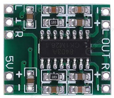
using a USB cable for the power and a jack from an old headset
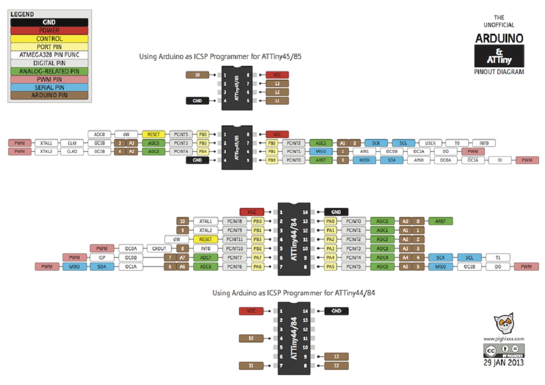
Atmel Tiny45/85
-
Pinout
-
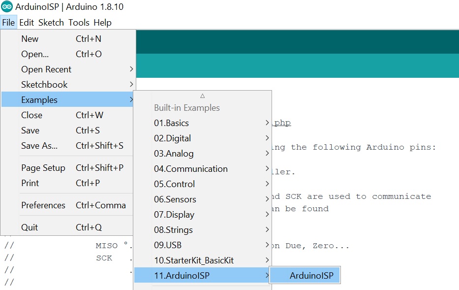
Progamming AtTiny45/85 using an Arduino as ISP
when you don't have an ISP programmer you can use an Arduino UNO to do it. As in my lab we have many unused Arduino and some development board stackable I decided to dedicated one for Attiny programming.
- Plug the arduino UNO and in Arduino IDE go to Files --> Examples --> 11.ArduinoISP
- Select the Arduino UNO board and the COM Port
- Then Upload the program to the Arduino UNO
Your Arduino is now an ISP : an In-System-Programmer that is used to program AVR microcontrollers. You can use the Arduino ISP to upload sketches directly on the AVR-based Arduino boards without the need of the bootloader. Otherwise you can use it to restore the bootloader
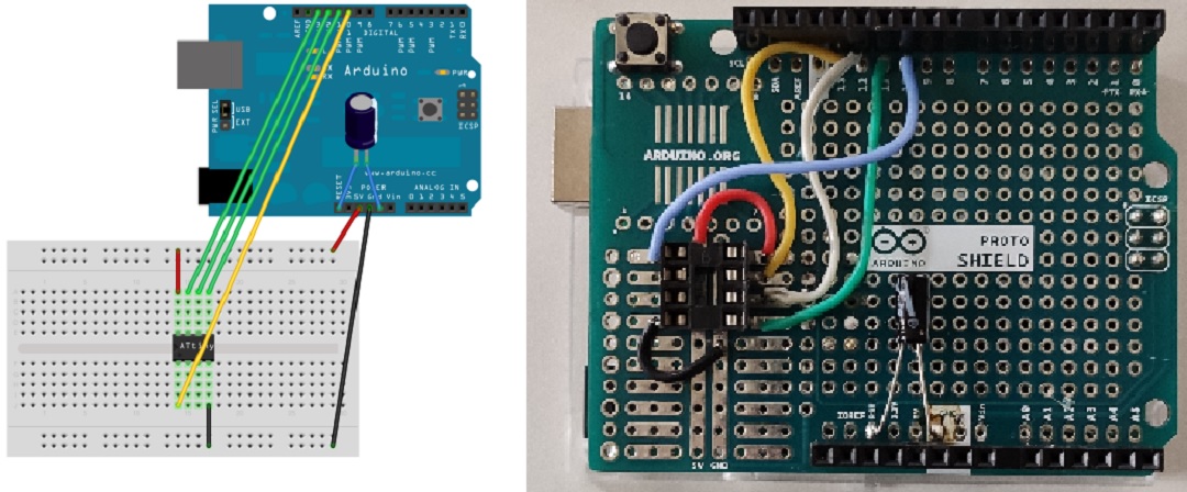
The following picture show you how to make the connexion between Arduino UNO and Tiny45/85 using a BreadBoard For My Lab I Made it permanently.
- ATtiny board Librairy are not under Arduino IDE by default, so you need to download them and add the folder under Arduino/hardware folder
It exists many Lib for ATtiny but I used to use ThisOne download the zip file, open it and copy the folder ATTinyCore-master under the hardware folder where is located your ArduinoIDE program.
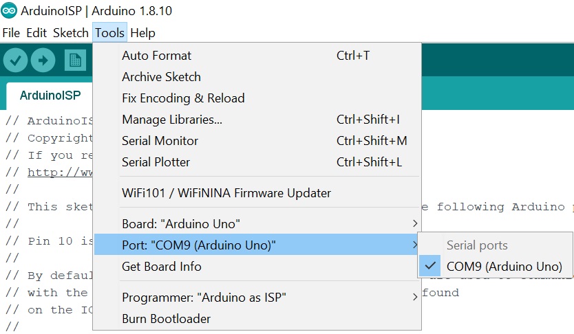
Now Under Tools menu you can select ATtiny25/45/85 for Board, then ATtiny85 for the chipset , the clock here 8Mhz internal, and do not forget to select Programmer:"Arduino as ISP"
To test if your connection are ok you can burn the BootLoader (bootloader: Microcontrollers are usually programmed through a programmer unless you have a piece of firmware in your microcontroller that allows installing new firmware without the need of an external programmer. This is called a bootloader.)
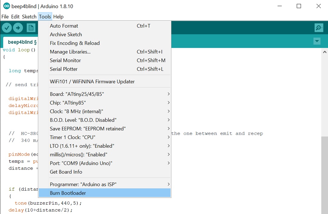
if success on the bottom your Arduino IDE you will have " Done burning bootloader"
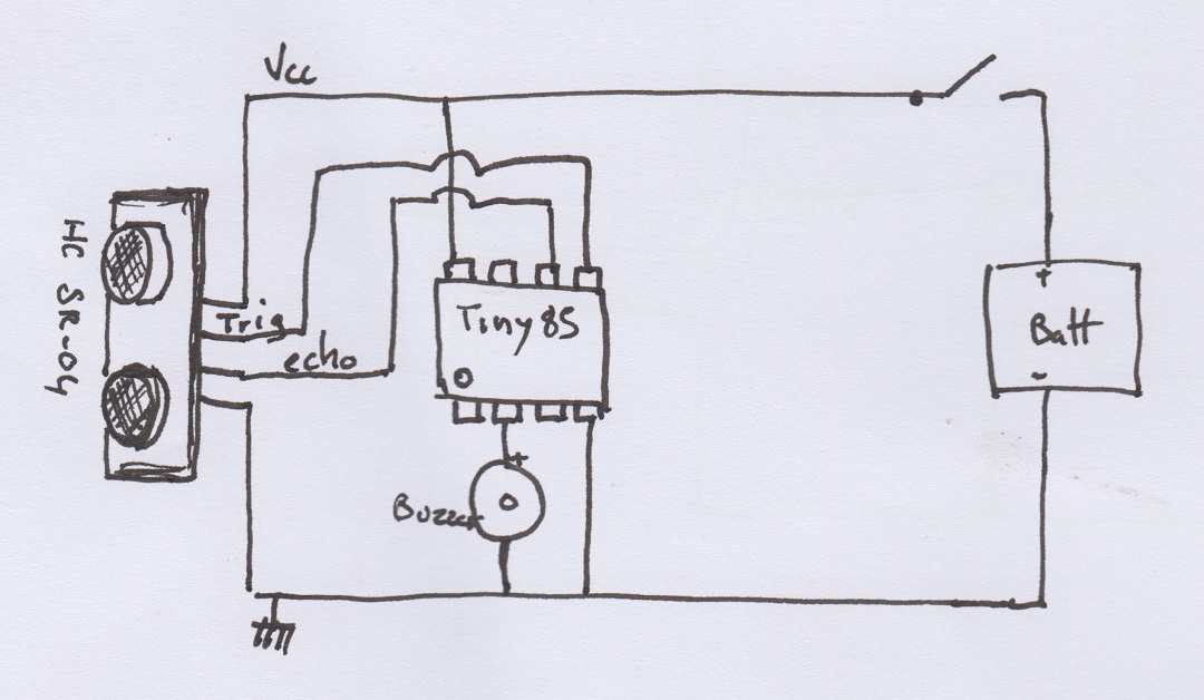
Application : cap for blind people
I want to equip a cap for blind people with a proximity detector and a buzzer. Because their cane and arms do not tell them about objects at the level of their face
I will use a ultrasonic detector HC-SR04, a buzzer and an ATtiny85
SOFTWARE:
/*******************ULTRASONS HC-SR04*************************

 **************************************************************/

// définition des connexions
const int trigPin = 0;  // pin "trig" connected to pin 5 of the ATTiny85
const int echoPin = 1;  //pin "echo"  connected to pin 6 of the ATTiny85
const int buzzerPin = 3; // buzzer on pin 2 of the ATTiny85


void setup() {

// init IO
  pinMode(echoPin, INPUT);
  pinMode(trigPin, OUTPUT);
  pinMode(buzzerPin, OUTPUT);
  digitalWrite(trigPin, LOW);
}

void loop()
{

  long temps, distance;

 // send trig

  digitalWrite(trigPin, HIGH);
  delayMicroseconds(10);
  digitalWrite(trigPin, LOW);


  //  HC-SR04 emit high level with a duration equal to the one between emit and recep
  //  340 m/s speed of sound --> dist = time/

  pinMode(echoPin, INPUT);
  temps = pulseIn(echoPin, HIGH);
  distance = temps * 340/(2*10000);


  if (distance < 100)
  {
    tone(buzzerPin,440,5);
  delay(10+distance/2);
  noTone(buzzerPin) ;
  delay(10+distance/2);
  }

}
Next version
this one won't be made of wearable because I want to be able to adapt the device on any cap and I want it reliable
I also want to add a vibrating motor
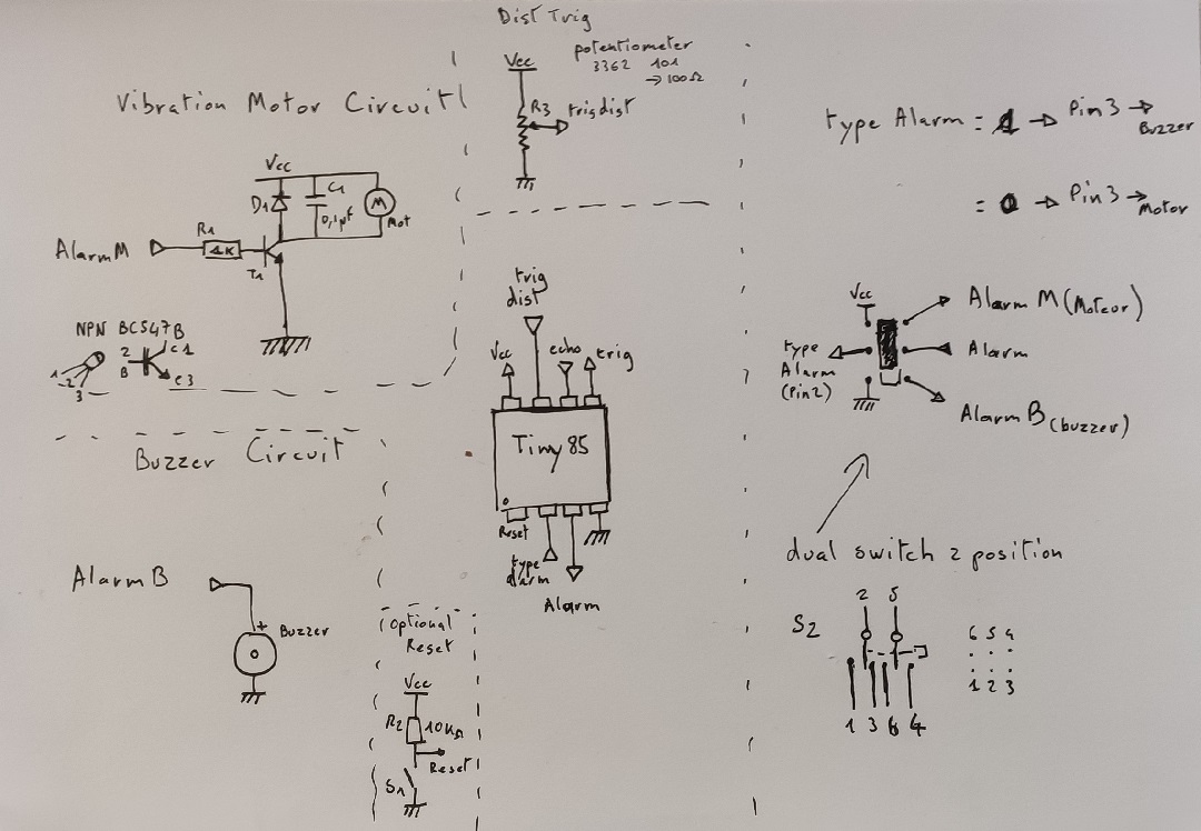
So the idea is to make a PCB, using a tiny85 so I have 5 PIN available, I will use them as follow:
- pin5 for trigger (output)
- pin6 for echo (input)
- pin3 for the buzzer/vibrator (output)
- pin2 for selection (buzzer or vibrator) (input)
-
pin7 for the with a potentiometer (input) to set the distance from which it start beeping or vibrating
-
pin1 reset (because the type of alarm and the trigger distance will be fixed in the setup phase to reduce instruction in the loop, so if you change them you will have to reboot)
- pin4 GND
- pin8 vcc
Schematic on paper (idea)
Creating the eagle schematic
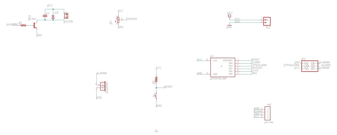
For the PCB I used EAGLE, basically I spent one hour to find all the componants I need, Then I group them by fonctionality. I prefer using the 2 commands LABEL and then NAME to make the connexion between componant rather than drawing them, it s a way more clear and with this method you are sure to do not forget anything.
Then you pass to The board with the cabling itself
Here the difficulty is that I only have single side PCB and its also more complicated if you use pass through tech rather than surface tecnologie (like before CAM remember to mirror your PCB design)
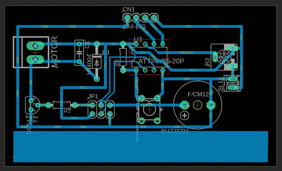
Then you have to pass to the CAM software
I do not have Fusion so I will export the design as a PNG and use the Fabmodules.org which will generate the "Gcode" for the MDX40A
to do so you have to select all the layer you don't want and hide them
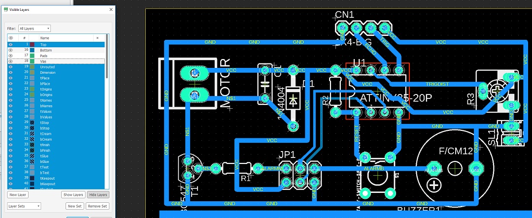
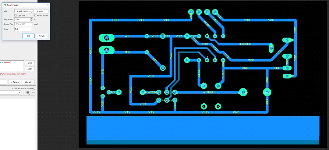
then you obtain this pict (here in JPG rather than PNG because of the space) from which with a basic graphic editor you can create one file for trace, one for holes and one for the cutting of the PCB
(note : with surface componant you don't have to worry about holes but with pass through I prefer to create one file with holes, one where you fill the holes using the bucket tool)


NOTE : Pass through Componant --> Mirror the PCB (otherwise you have to solder your componant on the cooper side)
Fab Modules
go to fabmodules.org
clic on input Format --> image(.png) and load the PNG file
set the DPI used when export from Eagle
Output Format : Roland Mil(.rml) process for trace PCB traces(1/64) On the right select the machine for me it: MDX40
and all the parameters ZERO - cut depth , diameter of the tool (for me I put 0.1 mm) , nb of offsets I will say 2 to 4 is enought (-1 will get ride of all the used copper but time and bit consuming)
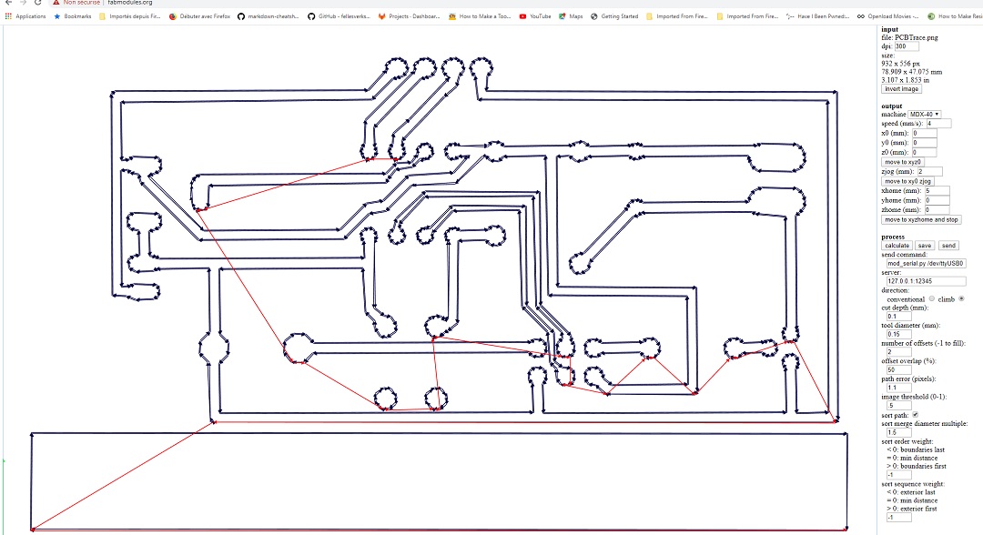
check if all your traces are ok ( a part with a thickness < diameter of the tool won't be removed. ex if you try a line between two pins and id there is not enought space for the tool to pass : it won't pass)
if everything is ok clic on save to save the RML file for the MDX40.
After that, like I did for the mold in section 9. (Textile as scaffold) I run the job from the Vpanel:
Set the X0, Y0, and Z0 and run the job by pressing cut, loading the rml file and clic on output.
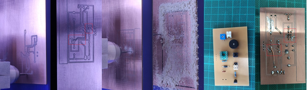
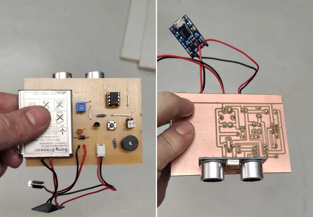
result: The first tool I used was very old not very efficient, also I only have a 1 mm tool to make the holes, so I have to stop.
The day after Sebastien from On'lfait gave me a new 1mm and a new .5mm to make the holes and cut.
the result was great but I realise that making PCB for CMS or for pass through is totaly different, it s a nightmare to solder on small PADs.
it looks good from componant surface but pretty ugly from the copper side.
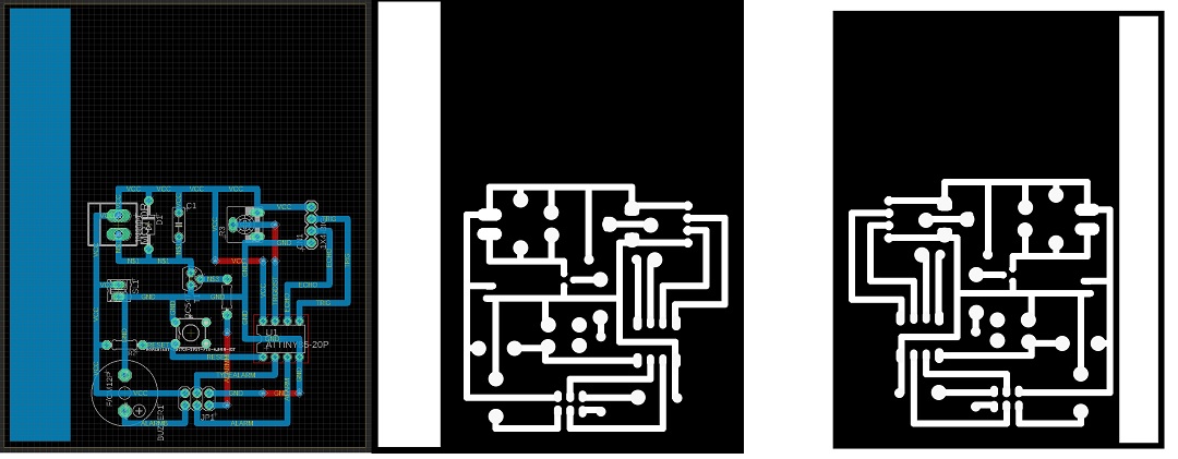
So starting from the same schematic I redo the board: take more space, avoid passing between pin, use a bigger thickness for wire even using jumper rather than strange path.
Then when the png was done I quickly review all the PADs size to support old fashion electronic pass through using photoshop.
the Program:
/*******************ULTRASONS HC-SR04*************************

 **************************************************************/

// définition des connexions
const int trigPin = 0;  // pin "trig" connected to pin 5 of the ATTiny85
const int echoPin = 1;  //pin "echo"  connected to pin 6 of the ATTiny85
const int TrigDistPin = A1; // potentiometer to set distance trig on Pin 7 of the ATTiny85
const int TypeAlarmPin = 3; // select type alarm on Pin 2 of the ATTiny85
const int AlarmPin = 4; // Alarm on pin 3 of the ATTiny85
int TrigDist = 0;
int IntensityVibration = 0;
bool TypeAlarm = "TRUE";

void setup() {

// init IO
 pinMode(trigPin, OUTPUT);
 pinMode(echoPin, INPUT);
 pinMode(TypeAlarmPin, INPUT);
 pinMode(AlarmPin, OUTPUT);
 pinMode(TypeAlarmPin, INPUT);


 digitalWrite(trigPin, LOW);

TypeAlarm = digitalRead(TypeAlarmPin);
TrigDist = analogRead(TrigDistPin);
TrigDist = map(TrigDist, 0, 1023, 20, 200);


}

void loop()
{

  long temps, distance;

 // send trig

  digitalWrite(trigPin, HIGH);
  delayMicroseconds(10);
  digitalWrite(trigPin, LOW);


  //  HC-SR04 emit high level with a duration equal to the one between emit and recep
  //  340 m/s speed of sound --> dist = time/

  temps = pulseIn(echoPin, HIGH);
  distance = temps * 340/(2*10000);


  if (distance < TrigDist)
  {
   if (TypeAlarm)
   {
    tone(AlarmPin,440,5);
    delay(10+distance/2);
    noTone(AlarmPin) ;
    delay(10+distance/2);
   }
   else {
    IntensityVibration = map(distance, 0, TrigDist, 255, 0);

    analogWrite(AlarmPin,IntensityVibration);
   }

  }