10. E-Textiles and Wearables II
Assignment
- Document the concept, sketches, references also to artistic and scientific publications √
- Create a swatch using an ATtiny with one input and one output, using hard-soft connection solutions and battery √
- Create 2 actuator swatches. Test them with the Arduino or ATtiny √
- Learn how to program an ATTiny , add the libraries and links used for the code √
- Document the schematic and the programming code, the libraries added and the power requirements √
- Upload a small video of your object working √
- EXTRA POINT Integrate it to a project √
How will it be evaluated
- References : tutorial , links, inspiration
- Design : sketch , 3D modeling skills, Parametric modeling skills
- Fabrication : Capable of executing from file to production workflow, from 3D modelling to 3D printing , parameters, materials
- Documentation : Anyone can go through the process and understand
- Final outcome : Is the project assembled, functioning and complete
- Originality - Aesthetics : Has the design been thought through and elaborated
Files and Links
Workflow
- Research
- Program Attiny
- Create 2 actuator swatches
- Swatch using an ATtiny with one input and one output + battery
- Final result
Research
I have continued Week 5 - Wearables I work to finished the FABRI-LEGO project this week.
One of the main topics on this week is programming your ATTiny. In this case I am using a through hole ATTiny 85 that will be programmed by an Arduino UNO. Just to let you understand how to program a FABRI-LEGO I will let you a link of the protocol I’m using to program it. It is called ISP
Program Attiny
For Arduino Software part I recommend you to follow David Arias documentation because you will be able to follow step by step all the process that is what you need to do to program the FABRI-LEGO.
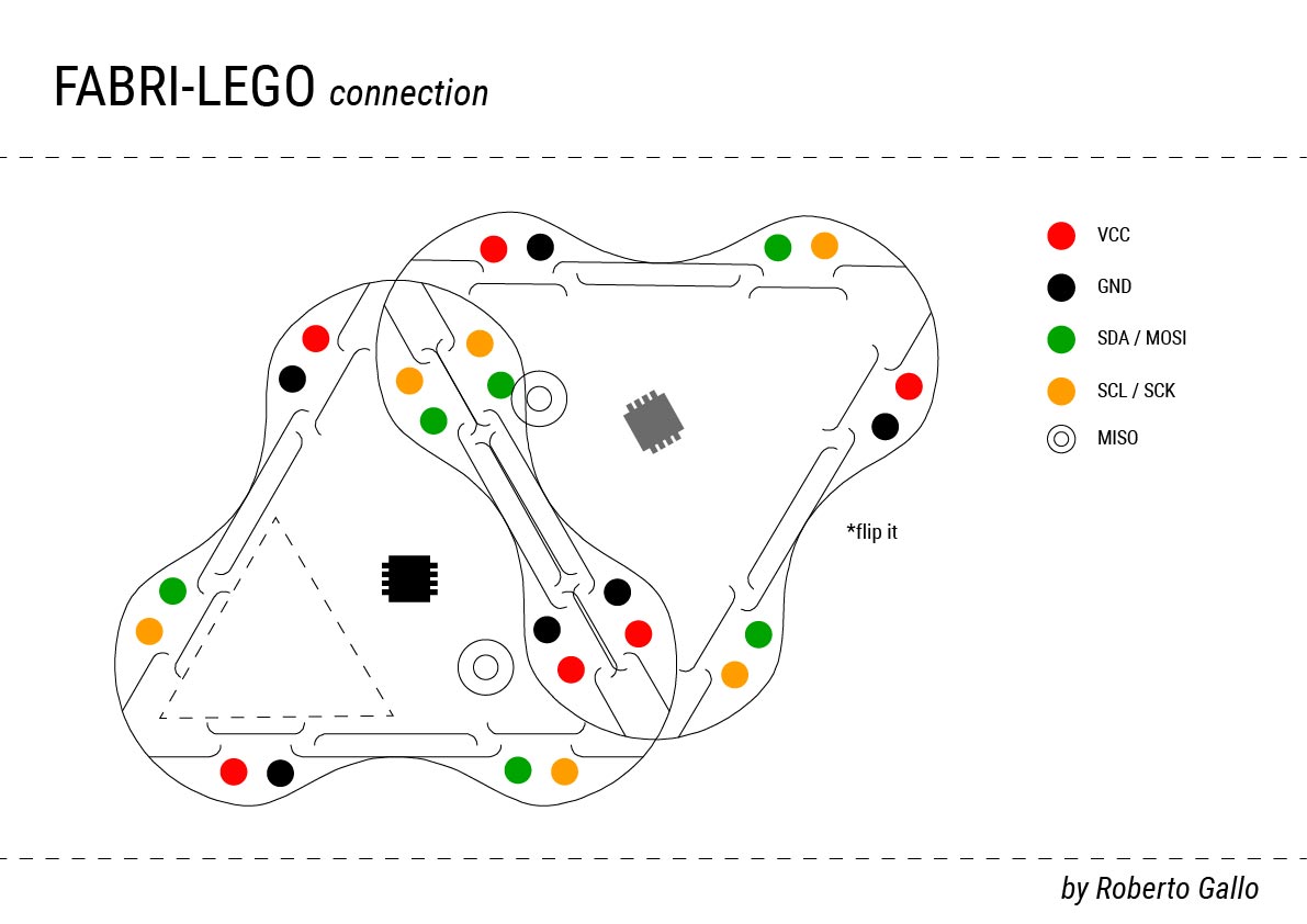
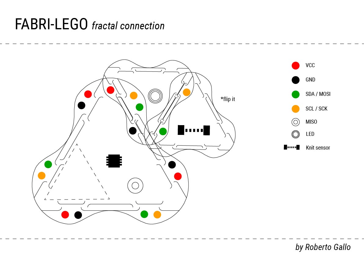
You may see in the next image the pinout related with ATTiny 85 microprocessor. This image it is super important to help you find all the pins related to ISP protocol.
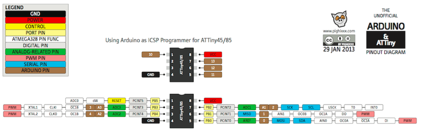
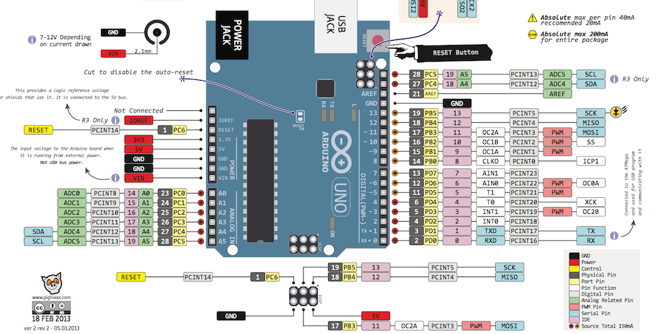
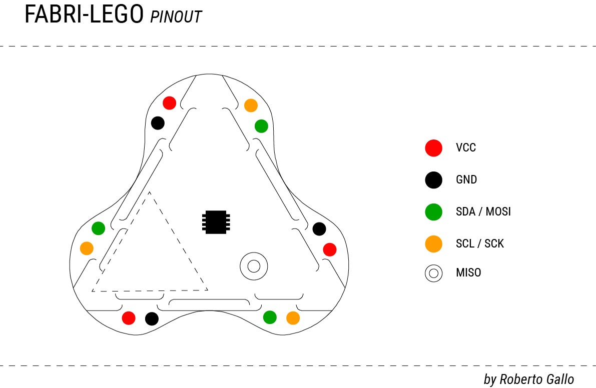
The same logic applies to Arduino UNO and FABRI-LEGO pin out.
And I had followed him in the first exercise until he finished. Then I started to follow the second exercise once I have understand the logic of where to find functions that I need. This was super good for me!! So I decided to complement first exercise adding more functions.
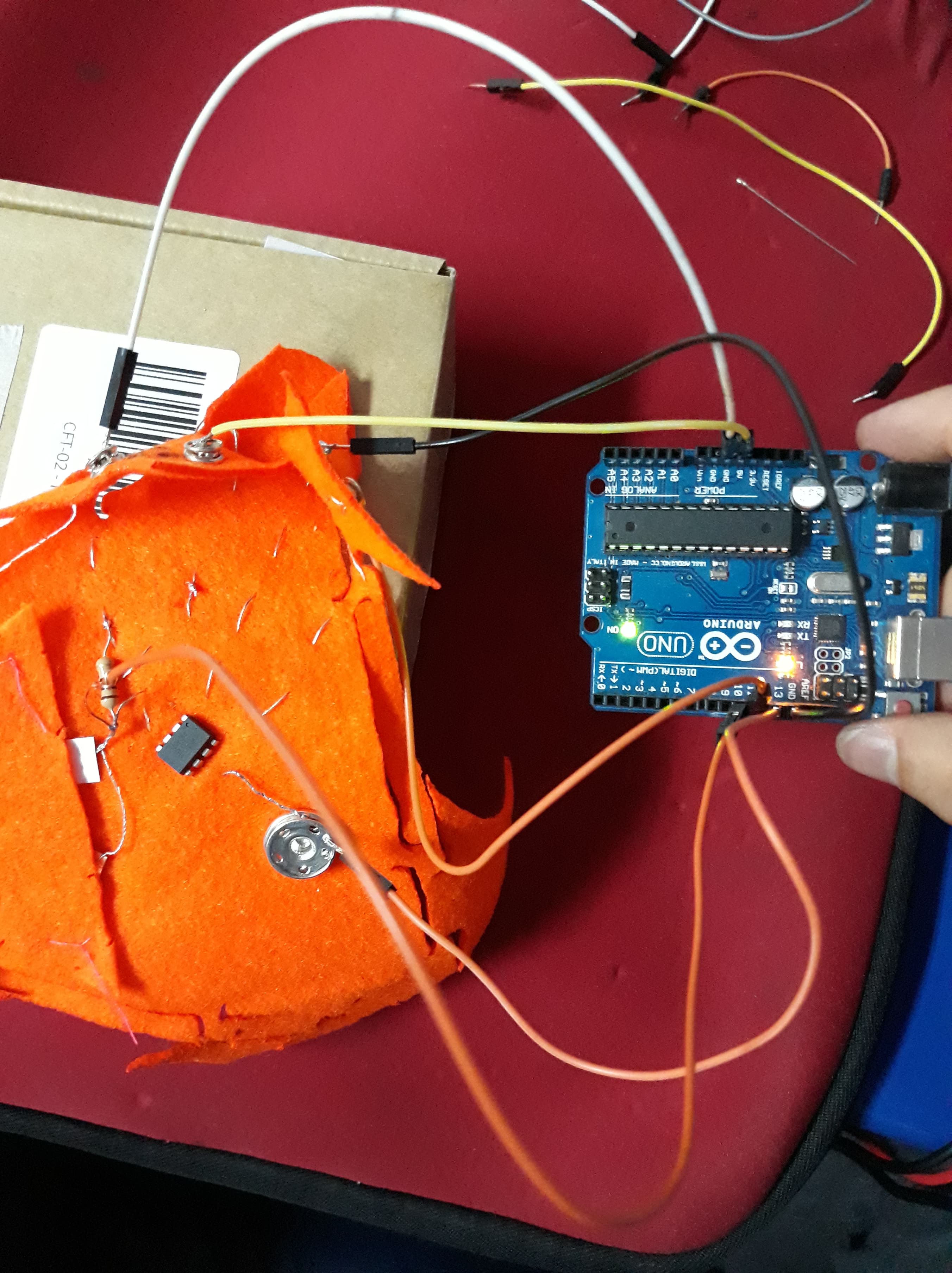
At this point you have all visual info needed to program your FABRI-LEGO. The main pins you need to find on Arduino UNO (our programmer) and FABRI-LEGO (our textile board to program) are MISO, MOSI, SCK, VCC and GND. You will connect Arduino UNO and FABRI-LEGO pins between each board (same names). You can confirm connection with the photo provided above.
this is the code I upgrade on FABRI-LEGO
int led = 1;           // the PWM pin the LED is attached to
int brightness = 0;    // how bright the LED is
int fadeAmount = 5;    // how many points to fade the LED by

// the setup function runs once when you press reset or power the board
void setup() {

  pinMode(led, OUTPUT);
  // initialize digital pin LED_BUILTIN as an output.
  pinMode(0, OUTPUT);
  digitalWrite(0, HIGH);   // turn the LED on (HIGH is the voltage level)
  delay(1000);                       // wait for a second
  digitalWrite(0, LOW);    // turn the LED off by making the voltage LOW
  delay(1000);
}

// the loop function runs over and over again forever
void loop()

{
  analogWrite(led, brightness);

  // change the brightness for next time through the loop:
  brightness = brightness + fadeAmount;

  // reverse the direction of the fading at the ends of the fade:
  if (brightness <= 0 || brightness >= 255) {
    fadeAmount = -fadeAmount;
  }
  // wait for 30 milliseconds to see the dimming effect
  delay(500);

  // otro scketch
  digitalWrite(0, HIGH);   // turn the LED on (HIGH is the voltage level)
  delay(100);                       // wait for a second
  digitalWrite(0, LOW);    // turn the LED off by making the voltage LOW
  delay(100);                       // wait for a second
}
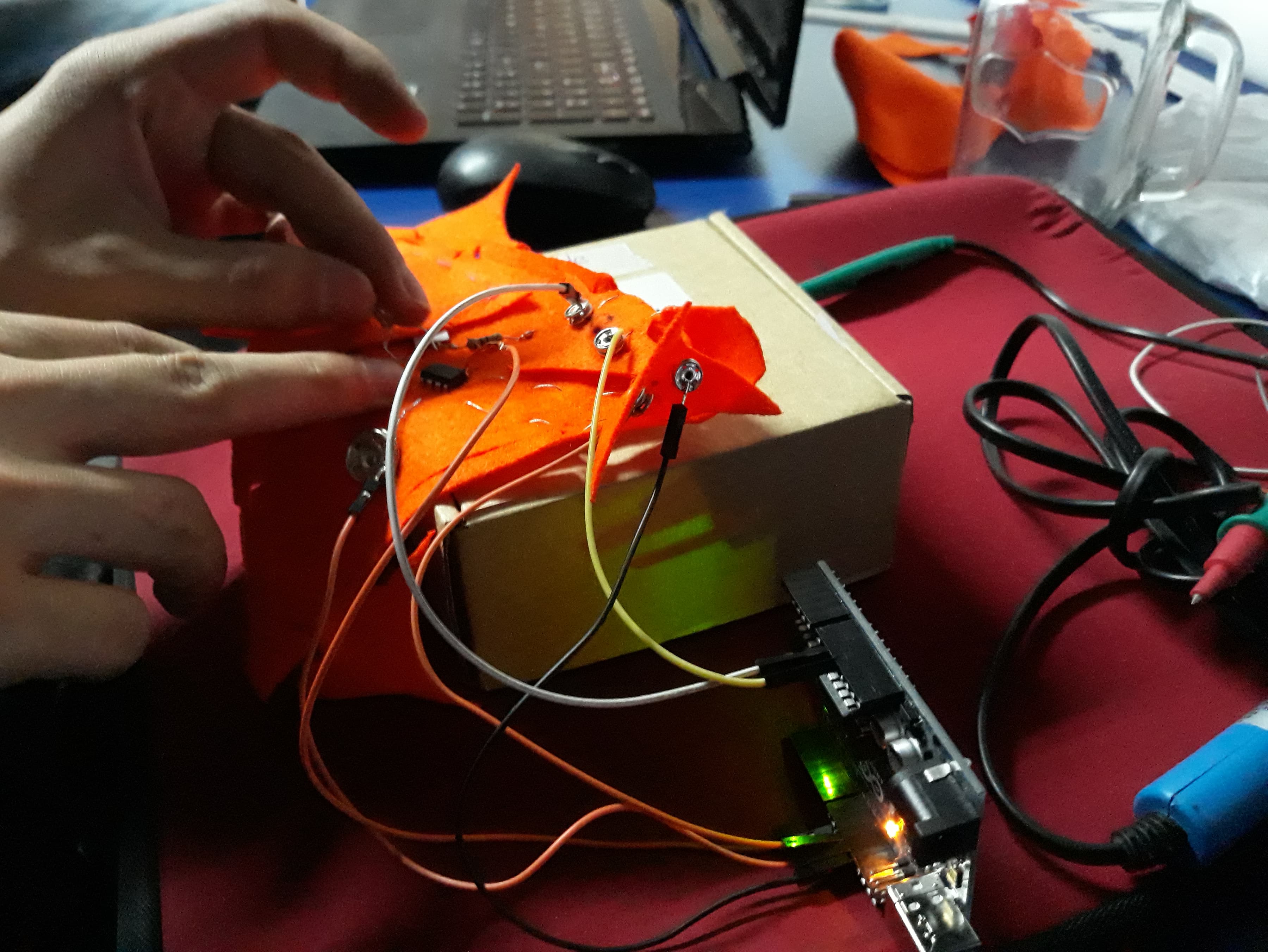
The test you see in the gif below is super easy and quick. With a led you can check if any signal is going out from the pins you have program just to know if they are working.
You may see the led once installed is blinking correctly. It is extremely important to work your PCB in the same voltage you will use your gadget. At the beginning I was working on 3.3 V and the blink was not fast and also bright as I wanted so I decided to change to 5 V.
FABRI-LEGO have two ways to connect:
Normal connection: The one that join two swatches that have same scale.
Fractal connection: The connection that join two swatches of different scales.
Create 2 actuator swatches
Heat
The first actuator that I started to build is a resistance to produce heat and I use a scaled swatch to add to my first module. Ones I finished saw I started to measure how much heat I can produce with my programing. I add this feature to 5th pin of ATTiny 85.
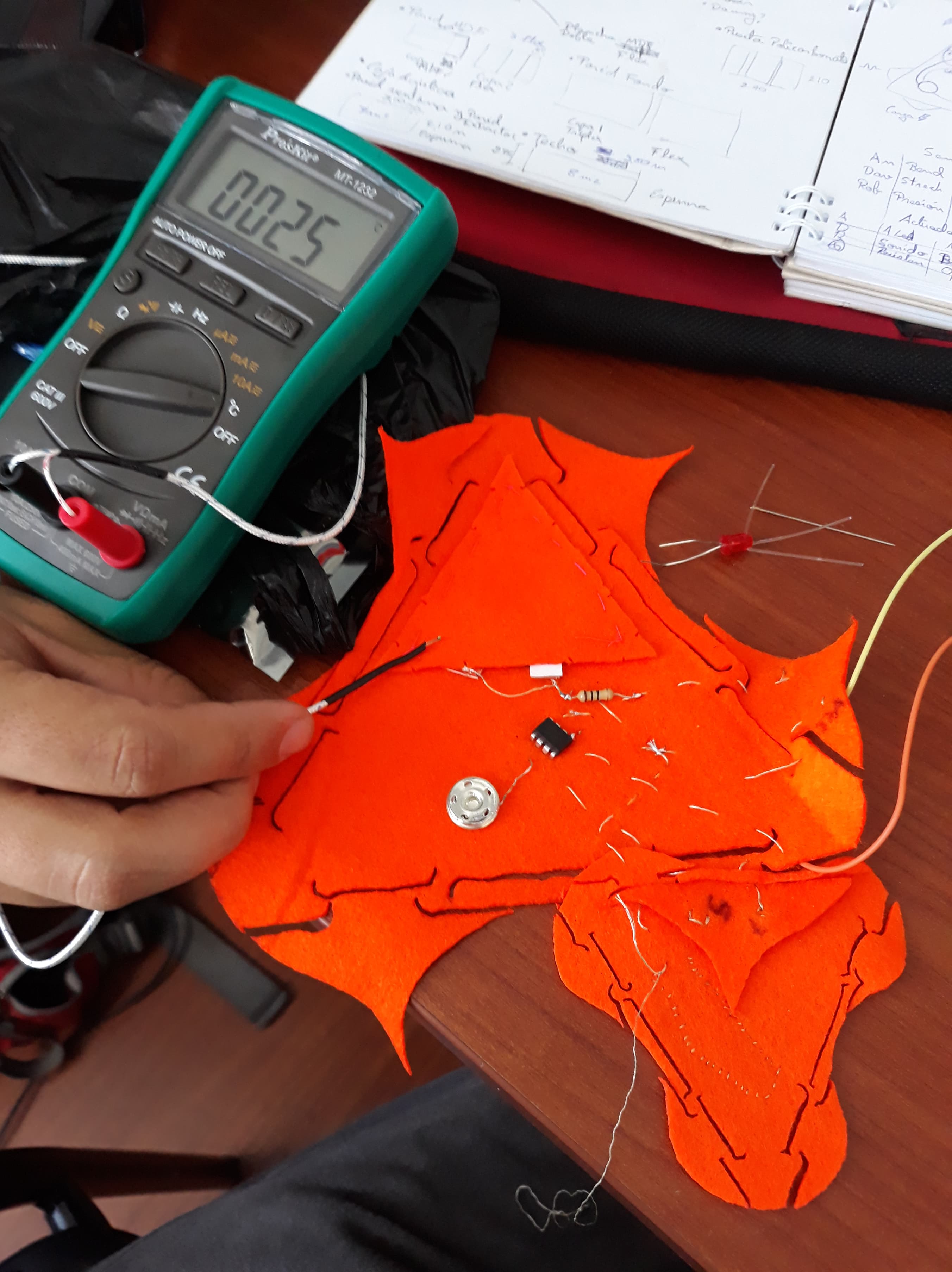
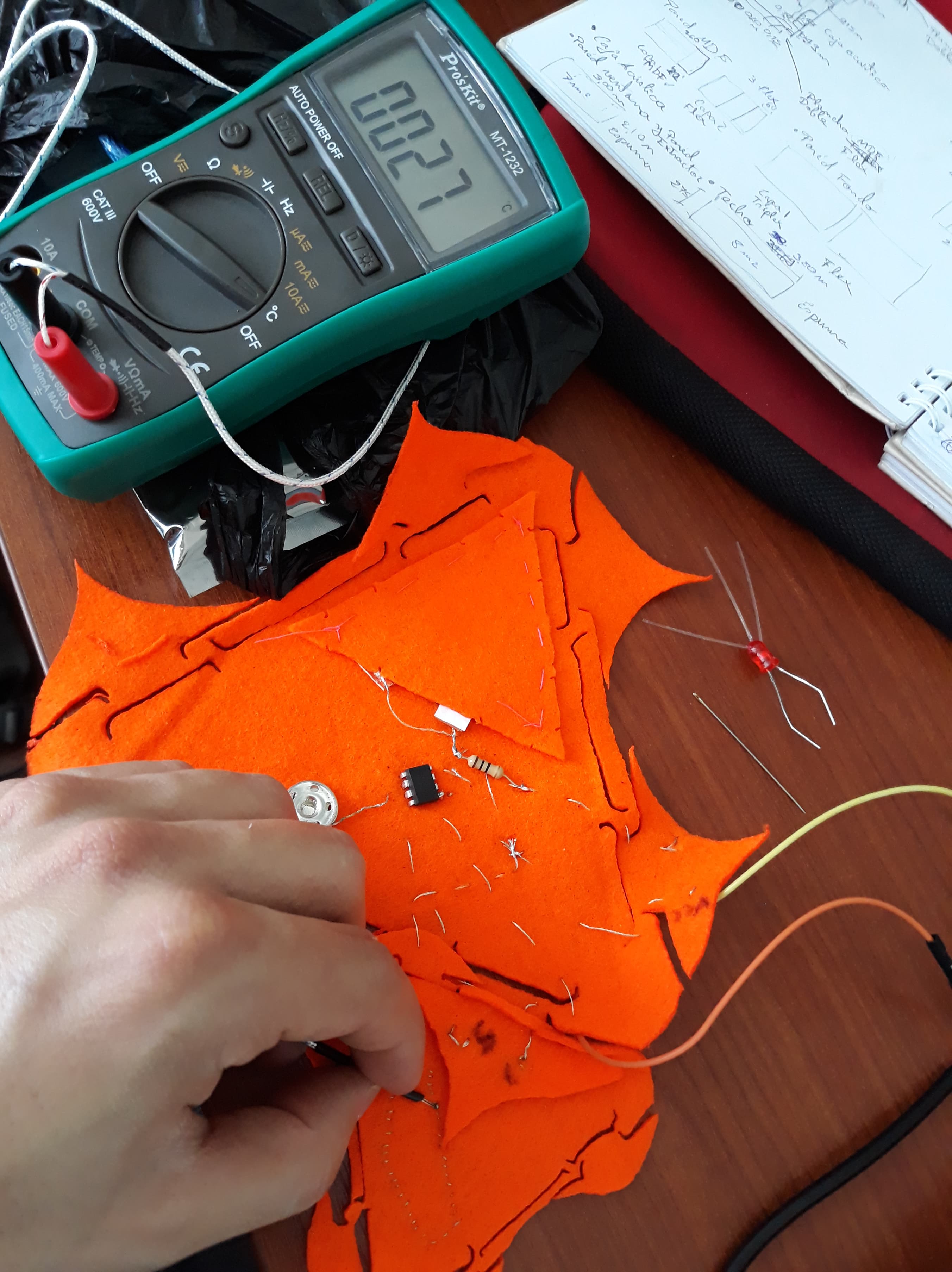
I was waiting to increase at least 5 Celsius degrees. When I measured with the multimeter I was increasing 2 Celsius degrees. Less than I was thinking but enough for the exercise. This was a first success try.
Led + Optic fiber
I was planning to do another swatch for my nice led with optic fiber but there was a little problem because my heat swatch was not as heater as I wanted. I was not clear when it was heating because human fingers are not capable to feel the change of 2 Celsius degrees. So I decided to try 2 thinks. 1St if I was able to use the resistance as a resistor to my led and 2dn if the led will be able to bright enough to be visible for human eye.
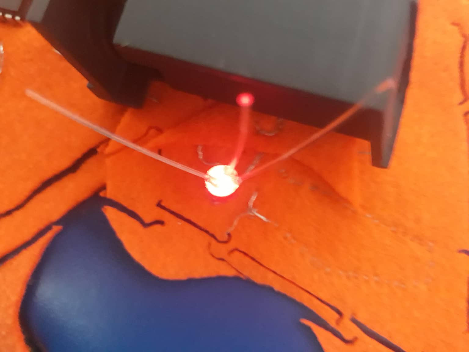
Fortunately all works good. At the beginning it was not as bright as I wanted that’s why I change the voltage and all looked great. It is amazing to be capable to make resistors with thread!
Swatch using an ATtiny with one input and one output + battery
#### Battery swatch
I also made another modular swatch to bring power to FABRI-LEGO. I have used a 500 mA lithium battery and a tp4056 charge module.
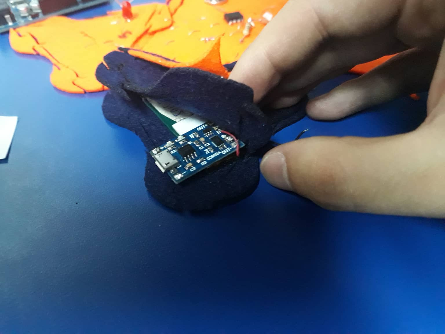
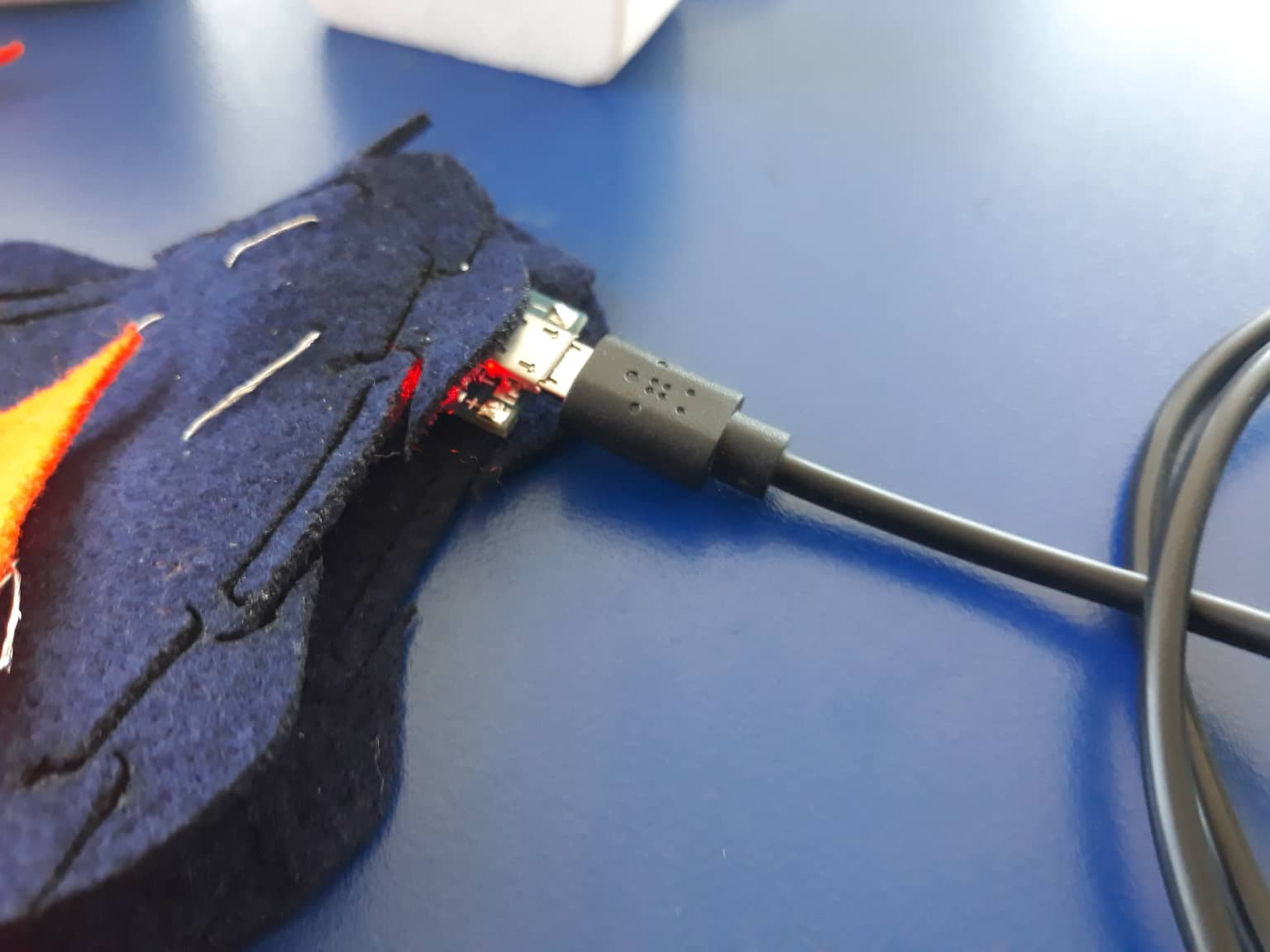
This is a nice way to turn on FABRI-LEGO!!
Input and Output
For this part I decided to use FABRI-LEGO fractal connection and use the sensors produced on Week 5 - Wearables I to integrate input and output swatches. For this propose I did two exercises, one on a digital pin and other in an analog pin.
Analog Pin - 5
This was a little bit funny because in building FABRI-LEGO process I kind of connect all swatches in opposite pins. I select my pressure sensor as a button to turn on the Led - Optic Fiber. The pin that receives the signal is 1st / RESET and this mean that I am receiving a digital signal and turn on the led that is connected on pin 5 / PWM. Next time I will select other pins for visualize better PWM pins. Anyways the exercise was successful and as you can see on gif all is working nice.

int led = 1;           // the PWM pin the LED is attached to
int brightness = 0;    // how bright the LED is
int fadeAmount = 5;    // how many points to fade the LED by

// the setup function runs once when you press reset or power the board
void setup() {

  pinMode(led, OUTPUT);
  // initialize digital pin LED_BUILTIN as an output.
  pinMode(0, OUTPUT);
  digitalWrite(0, HIGH);   // turn the LED on (HIGH is the voltage level)
  delay(1000);                       // wait for a second
  digitalWrite(0, LOW);    // turn the LED off by making the voltage LOW
  delay(1000);
}

// the loop function runs over and over again forever
void loop() {
  analogWrite(led, brightness);

  // change the brightness for next time through the loop:
  brightness = brightness + fadeAmount;

  // reverse the direction of the fading at the ends of the fade:
  if (brightness <= 0 || brightness >= 255) {
    fadeAmount = -fadeAmount;
  }
  // wait for 30 milliseconds to see the dimming effect
  delay(500);

  // otro scketch
  digitalWrite(0, HIGH);   // turn the LED on (HIGH is the voltage level)
  delay(100);                       // wait for a second
  digitalWrite(0, LOW);    // turn the LED off by making the voltage LOW
  delay(100);                       // wait for a second
}
Digital Pin - 7
It is nice to use Knit Sensor; I found it super textile-style. In this case I tried to connect my Knit sensor swatch as a third connection to see how modular is FABRI-LEGO. As you can see in the image there is the main swatch (de big one), a second one attached (resistance and led-optic fiber swatch) and attached to the second and not to the main is the third swatch (Knit sensor).
At the beginning I had some problems because the only free pin for my third connection was 7th , a digital pin. Knit sensor is better to connect to a PWM (analog pin) instead to a digital pin because it stretch capability. Anyway for this exercise propose it is enough good.
/*
  Fabric Sensors
  October 2018
  http://thesoftcircuiteer.net/soft-sensors/
  Liza Stark
  This sketch uses smoothing, constrain, and mapping to read a fabric...
*/

// Define the number of samples to keep track of. The higher the number, the
// more the readings will be smoothed, but the slower the output will respond to
// the input. Using a constant rather than a normal variable lets us use this
// value to determine the size of the readings array.
const int numReadings = 10;

int readings[numReadings];      // the readings from the analog input
int readIndex = 0;              // the index of the current reading
int total = 0;                  // the running total
int average = 0;                // the average

int inputPin = 13;
int ledPin = 11;     // select the pin for the LED
int ledPin2 = 10;     // select the pin for the LED
int ledPin3 = 12;    // select the pin for the LED

void setup() {
  // initialize serial communication with computer:
  Serial.begin(9600);
  // initialize all the readings to 0:
  for (int thisReading = 0; thisReading < numReadings; thisReading++) {
    readings[thisReading] = 0;
  }
  pinMode(ledPin, OUTPUT);
  pinMode(ledPin2, OUTPUT);
  pinMode(ledPin3, OUTPUT);
}

void loop() {
  // subtract the last reading:
  total = total - readings[readIndex];
  // read from the sensor:
  readings[readIndex] = analogRead(inputPin);
  // add the reading to the total:
  total = total + readings[readIndex];
  // advance to the next position in the array:
  readIndex = readIndex + 1;

  // if we're at the end of the array...
  if (readIndex >= numReadings) {
    // ...wrap around to the beginning:
    readIndex = 0;
  }

  // calculate the average:
  average = total / numReadings;
  // send it to the computer as ASCII digits
  Serial.print("Unmapped readings = ");
  Serial.print(average);

  Serial.print("\t");

  //change these numbers to the min and max you want to use
  average = constrain(average, 600, 1000);

  //map the average onto a range the LEDs can use
  int newAverage = map(average, 600, 1000, 0, 255);

  //print it out for debugging
  Serial.print("Mapped readings = ");
  Serial.println(newAverage);

  //constrain the new average again just in case
  newAverage = constrain(newAverage, 0, 255);

  if (newAverage < 1) {
    analogWrite(ledPin, 0);
    analogWrite(ledPin2, 0);
    analogWrite(ledPin3, 0);
  } else if (newAverage >= 1) {

    //write the new value to the LED
    analogWrite(ledPin, newAverage);
    analogWrite(ledPin2, newAverage);
    analogWrite(ledPin3, newAverage);
  }
  delay(1);        // delay in between reads for stability

}
Conclusions
FABRI-LEGO is amazing. For a first version it is enough to be used by Fabricademy community. I have noticed the importance to plan before starting connecting swatches witch pins you will use to connect in a logic order analogic and digital pins. I have enjoyed a lot connecting all different swatches and using this amazing textile materials provided by Fabricademy.