10. E-Textiles and Wearables II
Bits, atoms, and expression...
Since the development of transistors and chips the word has experimented a huge change.
Then, the analog world could be represented digitally, and interacting with our wolrld using computer mathematical models of reality made us improve procecess on almost any thechnology, form agricuture to space exploration.
Now, that technology could be also integrated in textiles, opening a door to wear sensors and actuators. For performing arts, the posibility to interact with the analog world potentiates our artistic expression, alwing us to leap between analog and digital music, and analog and digital signals.
Preparation of the programmer
If we are going to use a memeber of the ATtiny family microcontrollers, we need to include their library.
We do so using the Arduino IDE 1.8.11. You can find it at the Arduino site.
load the programmer sketch to the Arduino
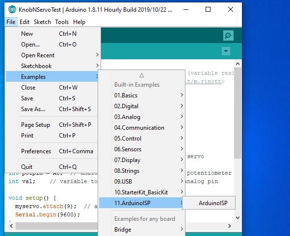
First, we look at the Examples in the file menu. There we'll find the ArduinoISP sketch example. Open it.
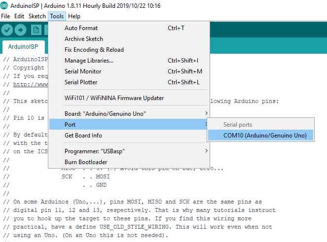
We have to be sure that our port is open and connected. In tools, choose port and then the arduino connected to your system.
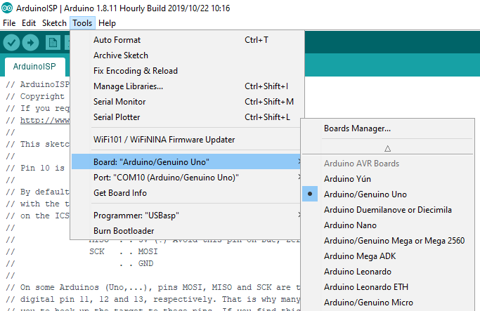
Be sure that the Arduino model you are using matches the setting in the Arduino IDE. To do that, go to Tools, Board, and then choose your model. This is important, because the software compiles the code accordingly.
implement the library for ATtiny chips on the Arduino programmer
There are severals ways to make our Arduino programmer captable of compile and burn programs on the ATtinyX. This method worked for me.
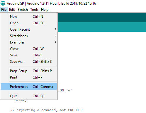
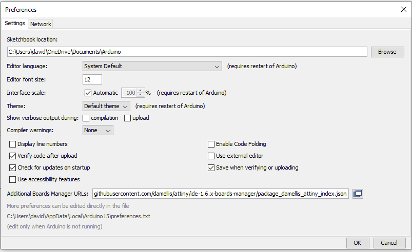
First, open preferences.
Then, in settings, paste the following web address:
https://raw.githubusercontent.com/damellis/attiny/ide-1.6.x-boards-manager/package_damellis_attiny_index.json
in the Additional Board Manager URLs Fields. This is a Json files, that will guide your system to the place to download the appropiate libraries. Clic OK.
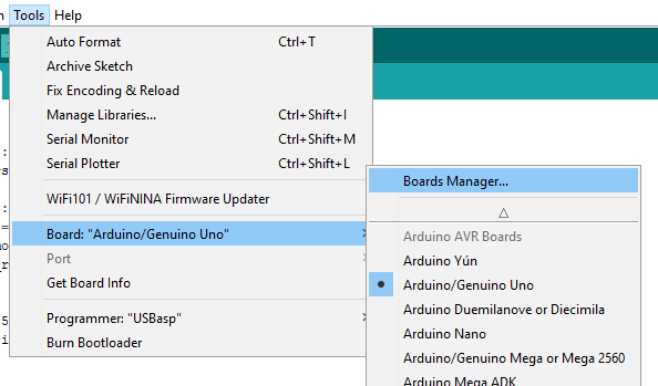
Then, go to Boards manager. You will find it in the Tools tab, under Board: "YourBoard".
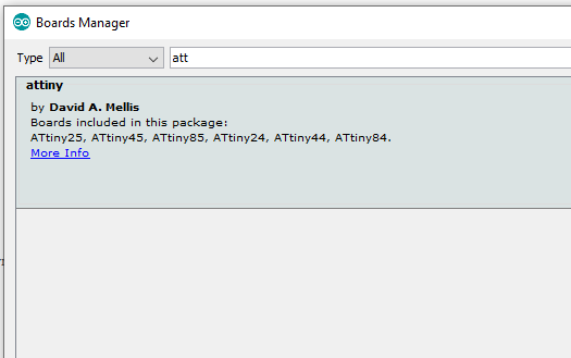
Once the Board Manager opens, you can scroll to the bottom or write in the search field. You will find the library attiny, by David A. Mellis. Install it.
After the installation, if everything went right, you will find at the end the chance to use various models of ATtinys.
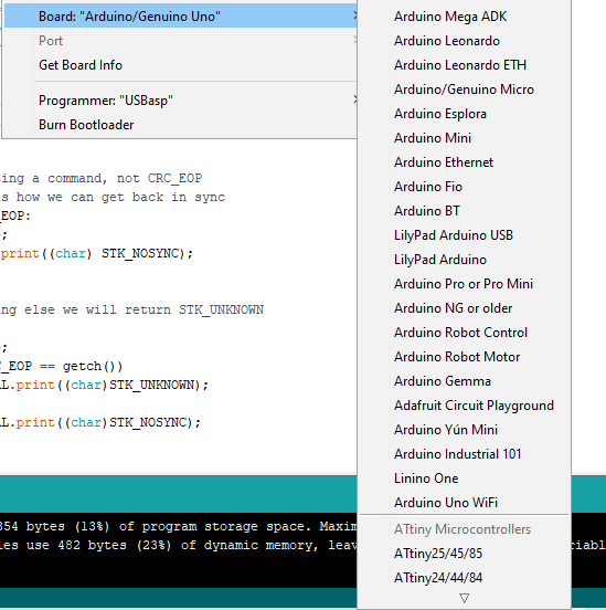
We are going to use the model ATtiny45. Therefore, we chose the first listed in the ATtiny options.
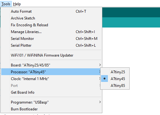
We are going to see an extra choice, the processor. We choose the one that fits our model.
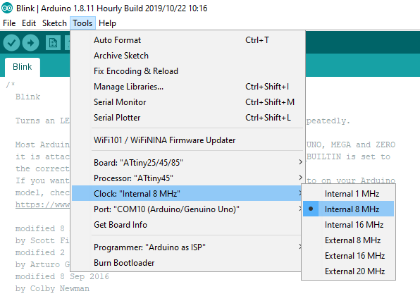
We are going to change the speed of the processor. We do so using the clock option. We are not using external resonating chrystals, so we choose the clock speed at 8 Mhz, internal clock.
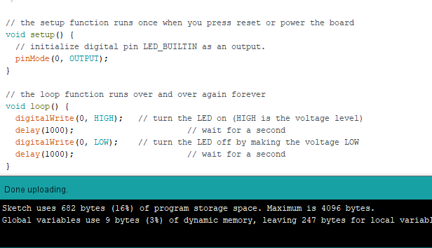
blink uploading
We are going to prepare the opload to the basic test program "blink" to the board. Let´s open it under our basic examples, and then change the LED_BUILTIN pin definition to 0 in the sketch. The ATtiny has no built in led, but has a 5 pin that corresponds to the 0 pin in the Arduino IDE compiler.
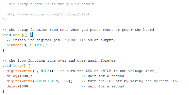
We set the blink rate to 1000 miliseconds (1 second) as an argument in our delay() function.
We hit upload, and if everything is set right, you will see the Done uploading message.
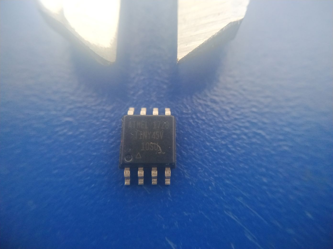
fabrication
For the fabrication we are going to start with the chip programming. Atmel 1728 ATtiny 45V.
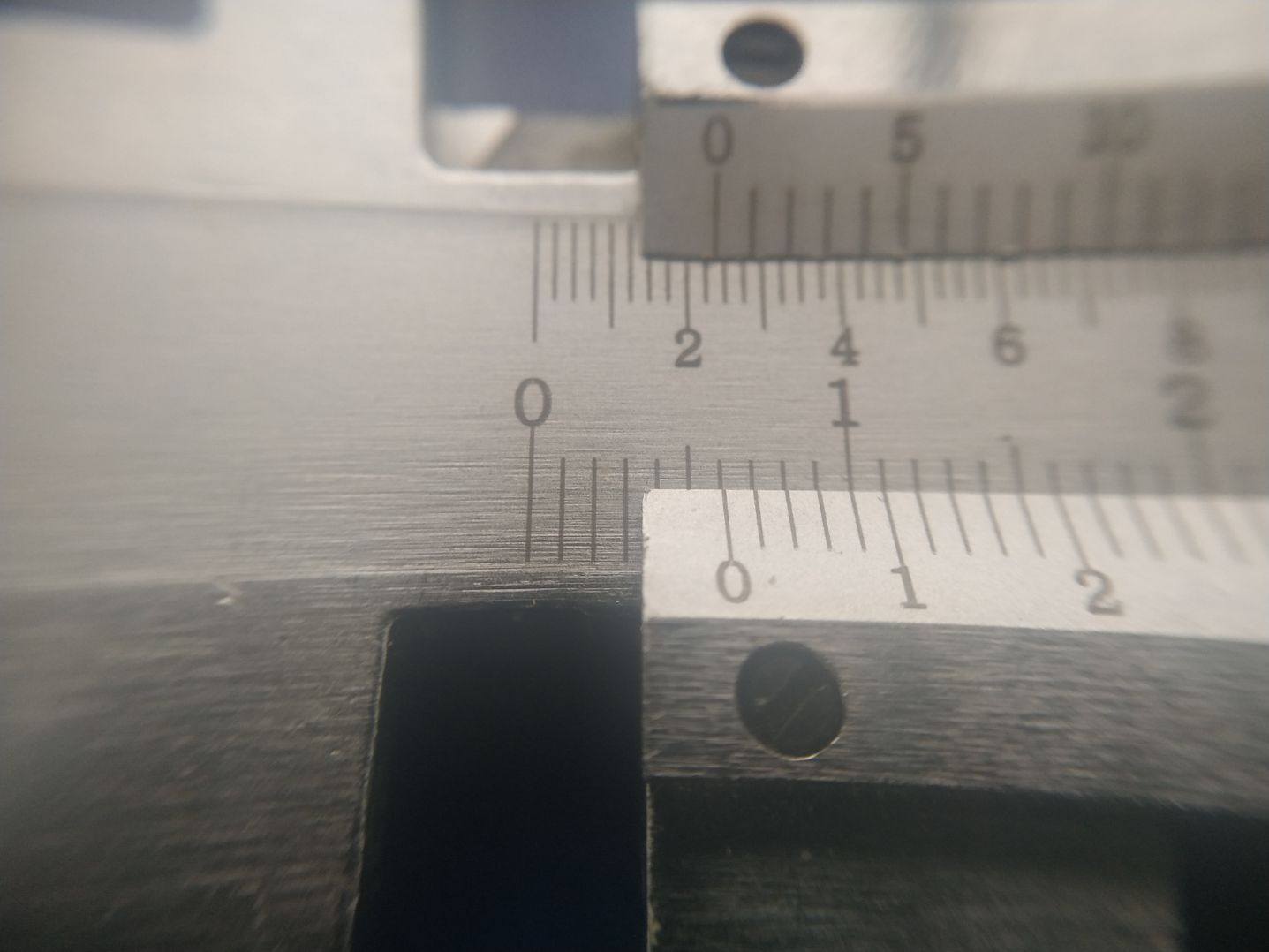
Here we have a surface contact version with a caliper to show the size.
We see that the size is 6mm (aprox.)
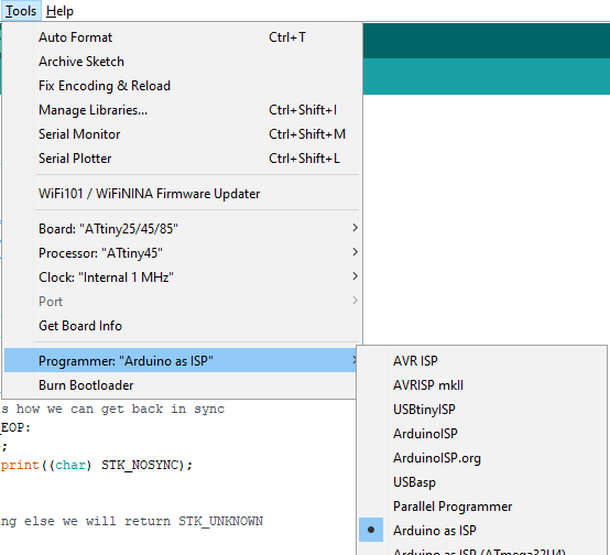
For programming, I am going to use an Arduino UNO R3, with the sketch that allows it to be a programmer.
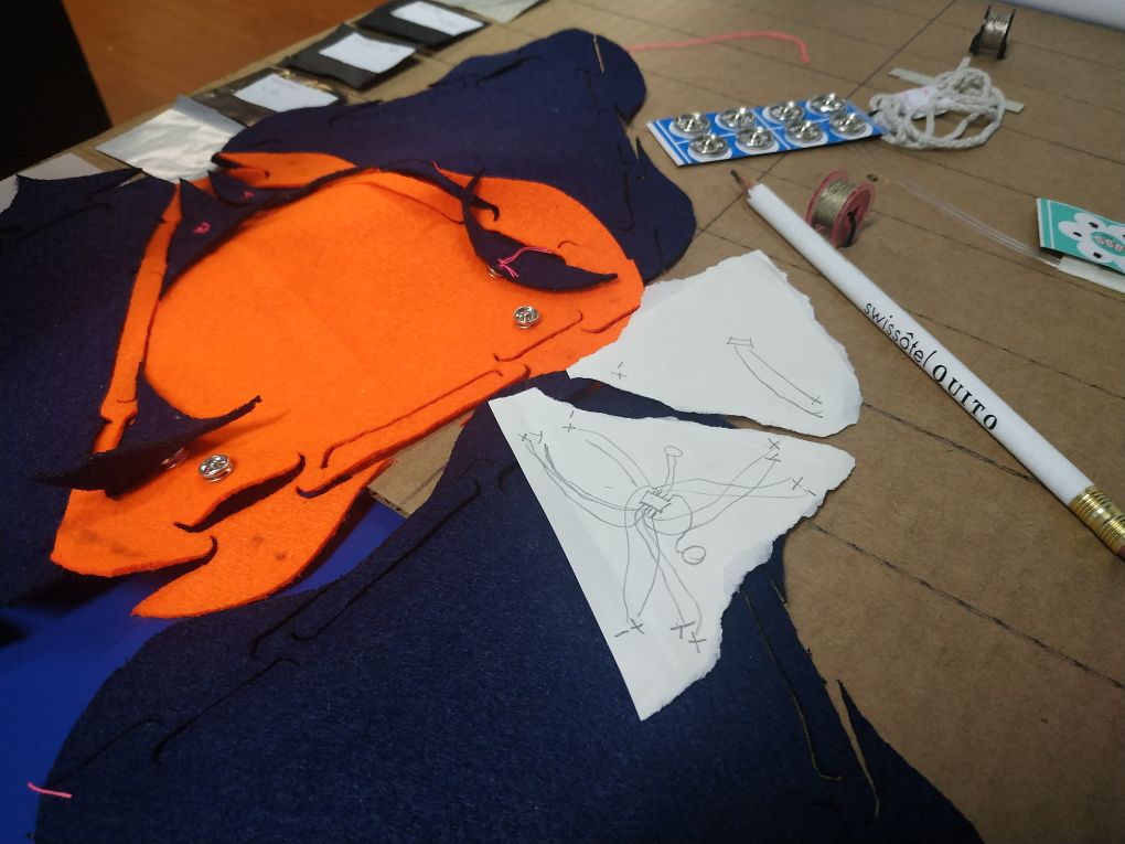
The wires and components are going to be placed in this modular swatches (potentially communicating with other units).
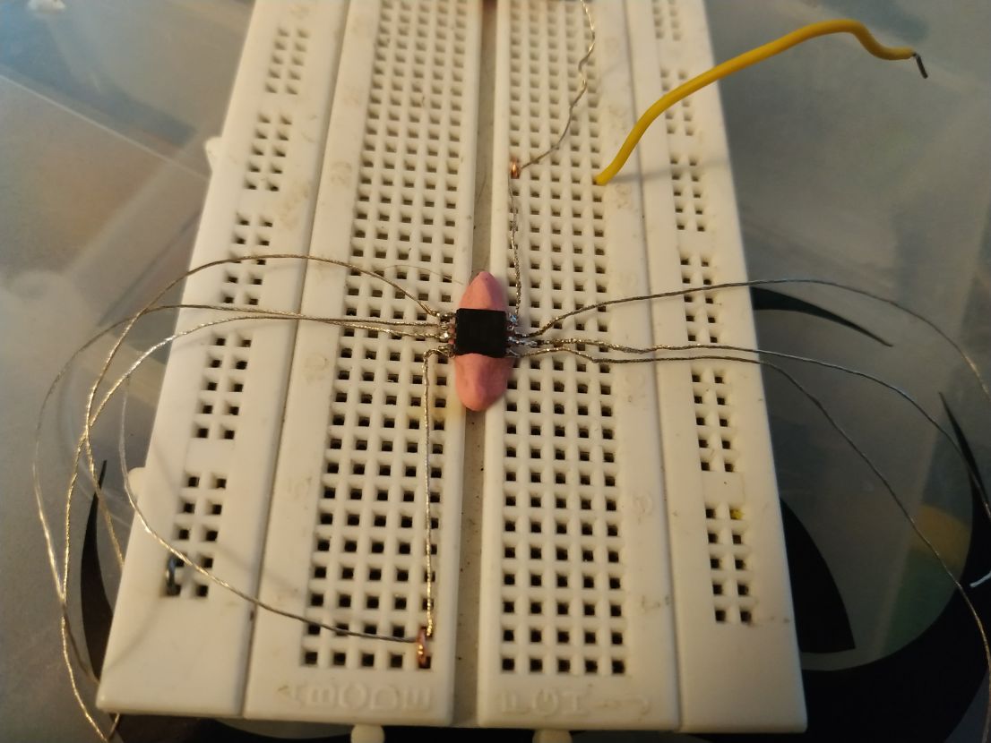
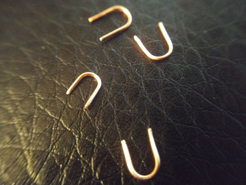
After carefully soldering conductive wire to the pins of the chip, I held it in place in the center of a breadboard using modeling clay. The wires are than conected and secured with U shaped pieces of standard wire.
Here we can see the U shaped wires.
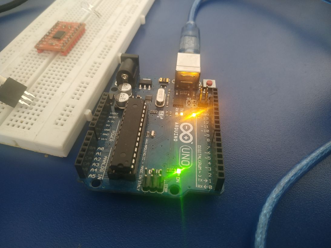
Once all the wires are secured, we can conect the standard cables to the programmer (Arduino Microcontroller with the ArduinoISP sketch)
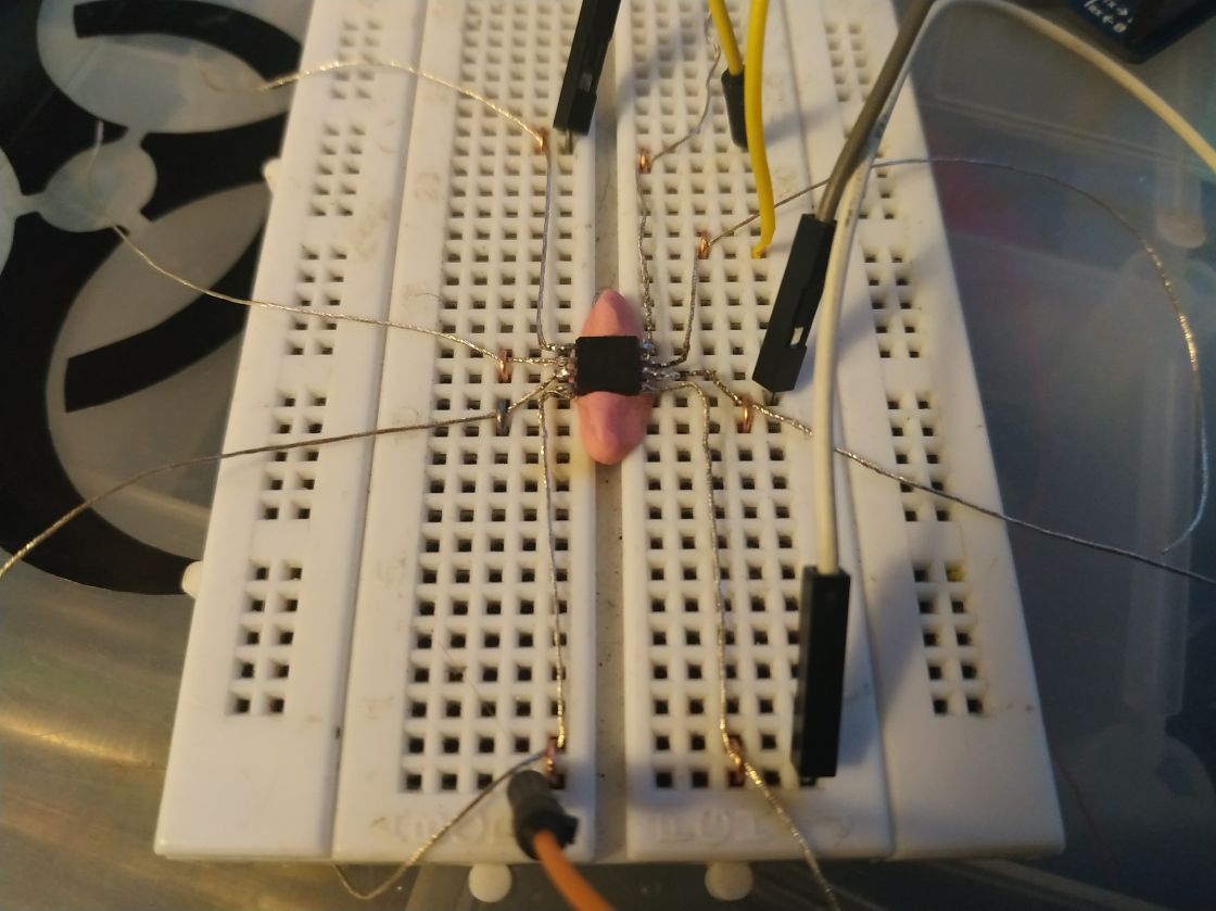
Finally, we conect a LED and a resistor, for testing the upload.
And it works! (blink sketch).
sensor/actuator mounting
We are going to test some soft sensors. First I tryied a variable resistor, elastic, silved-threated string. With the combination of a standard resistor we can make a voltage divider (for measuring voltage), replacing one of the fixed resistors in the configuration for a varible, conducting string.
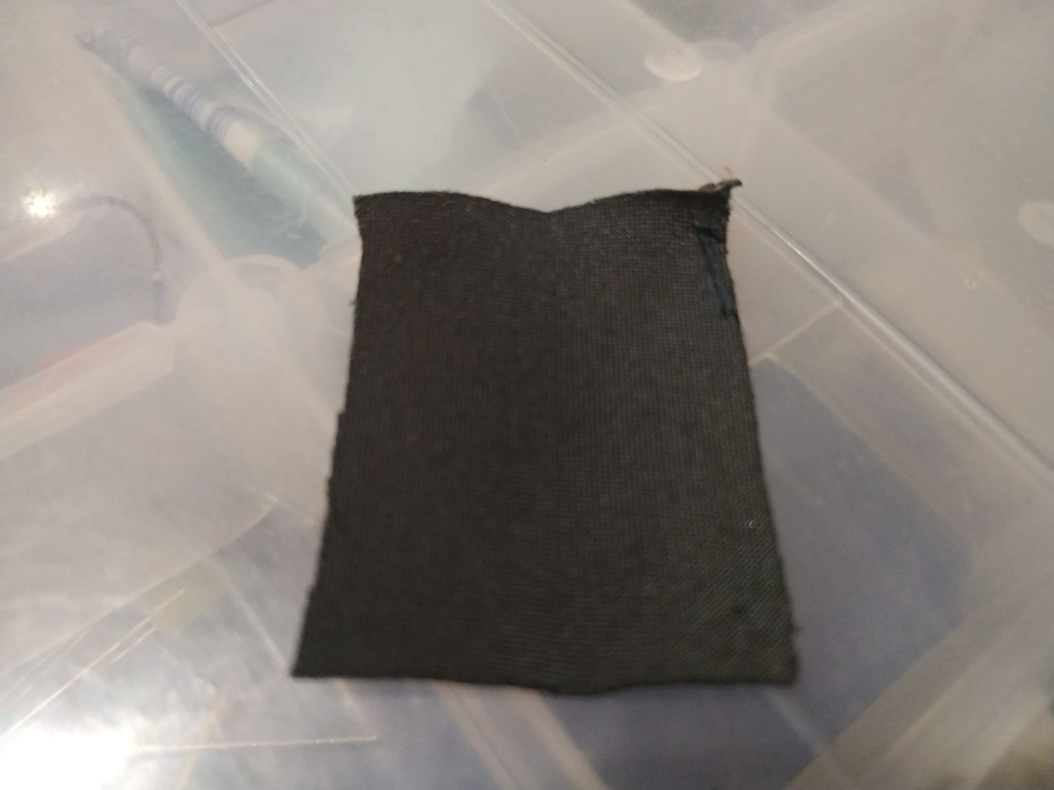
We also used a conductive cloth to use it as a capacitive sensor.
Here we can see the cloth. It is conductive.
I sewed the borders of the cloth, creating a tube.
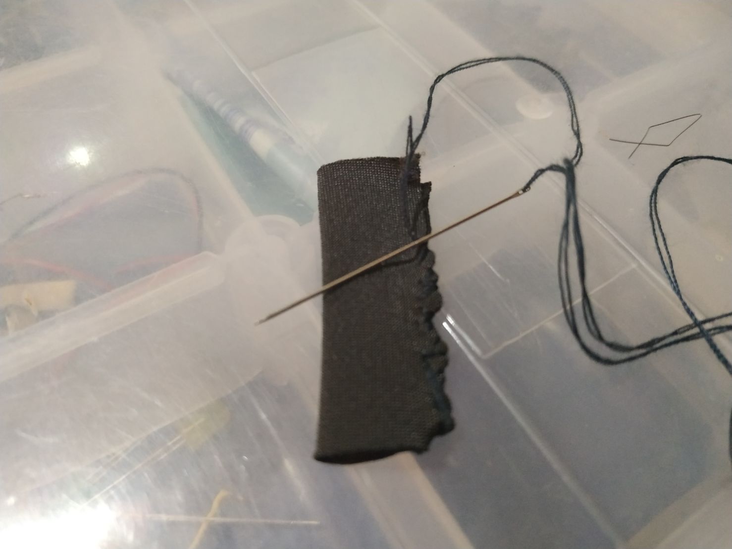
Here is the sewing completed.
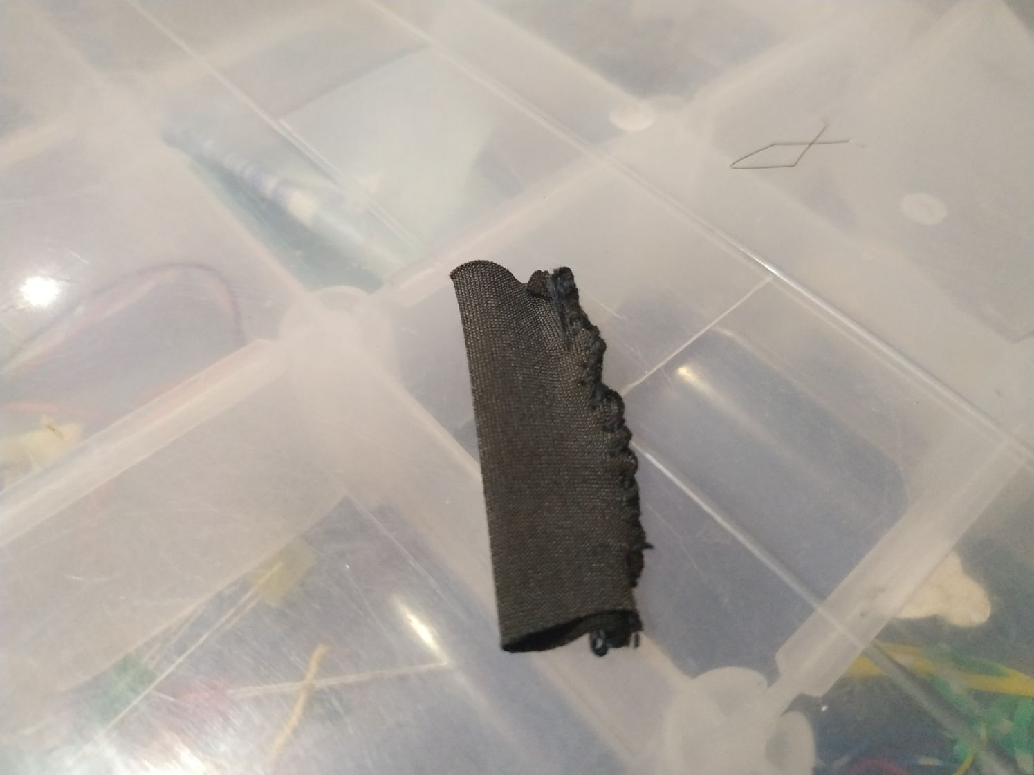
Then it was worked inside out.
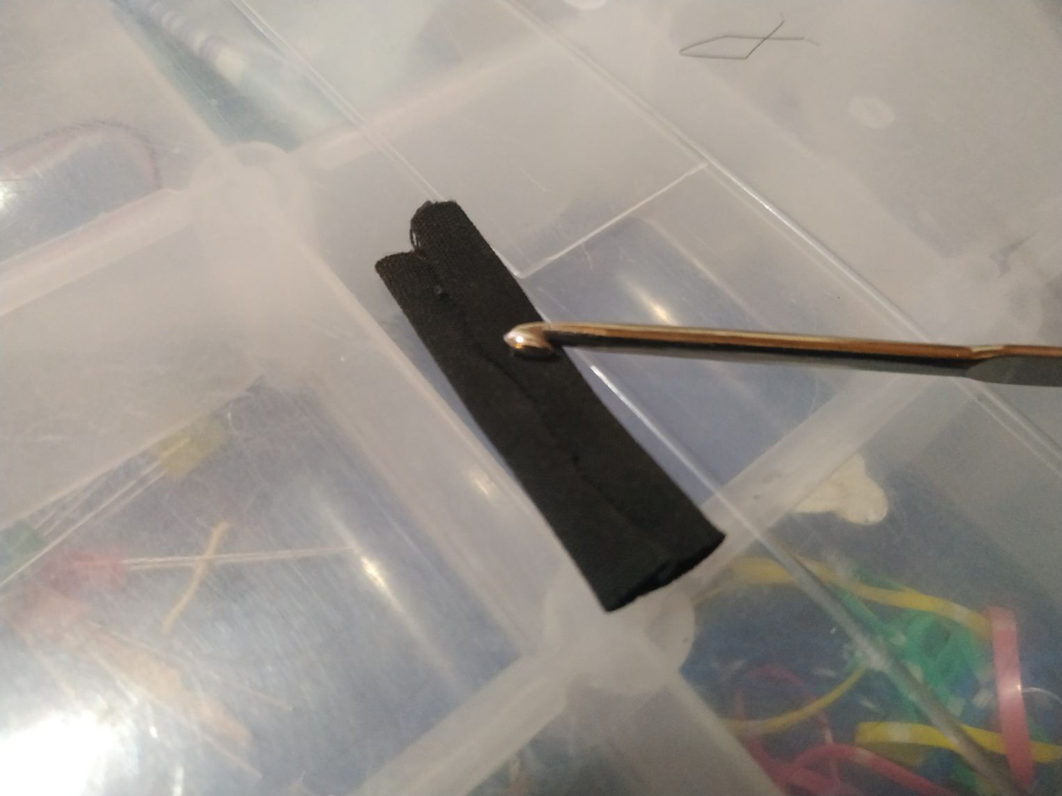
I used some cotton and a crochet tool to fill it up.
Then it was placed and sewed to the swatch.
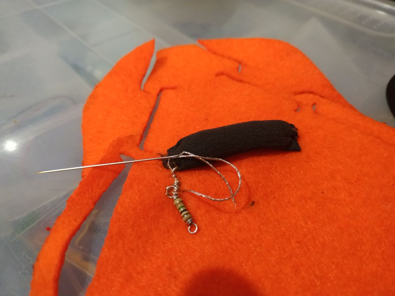
With players the wires of the resistor can be shaped.

This loops are easyly sewed.
Some conductive wire is threaded using an appropiate
And here we can see the loop of a resistor attached.
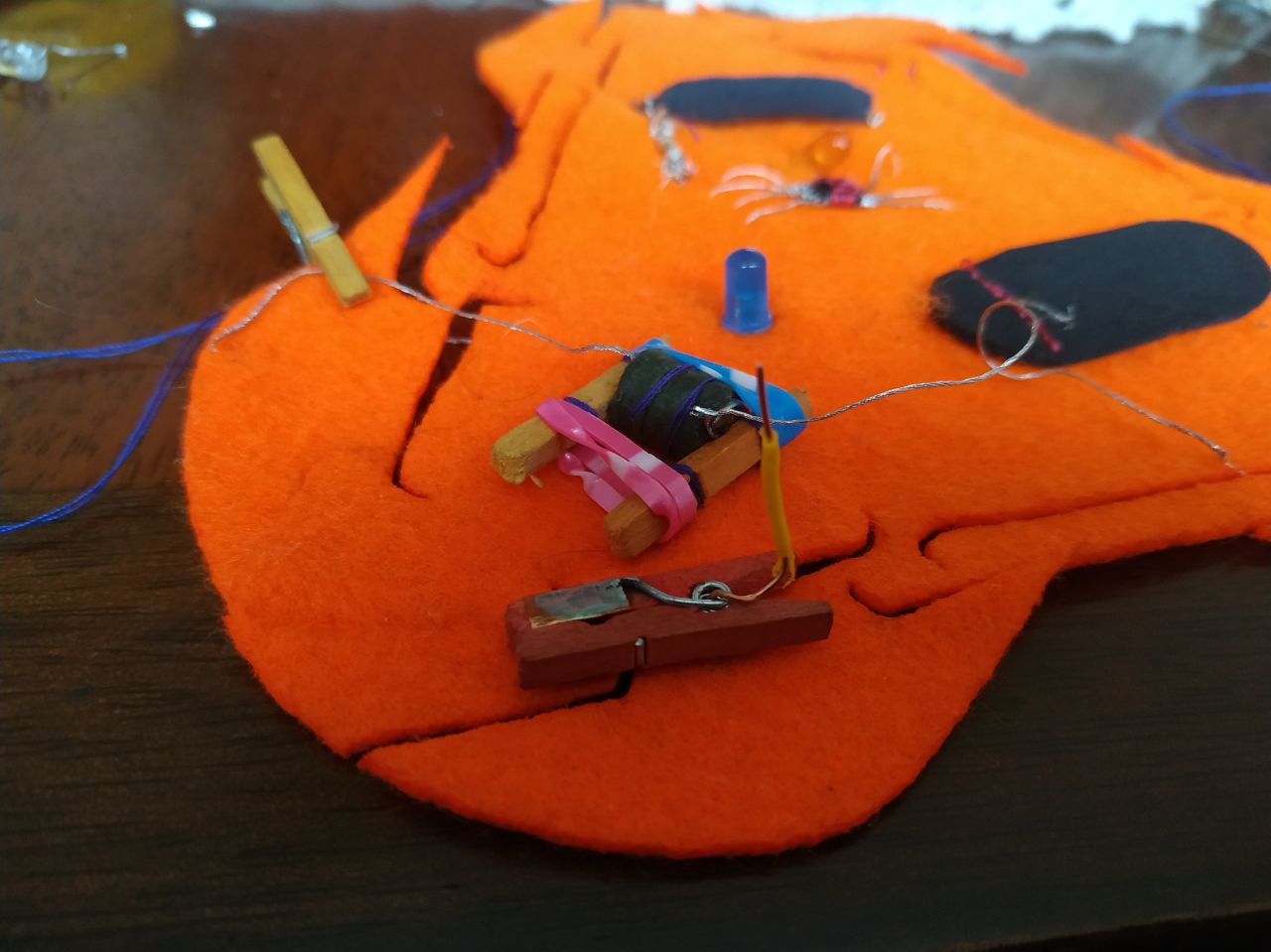
Then we use the breadboard to test the sensor.
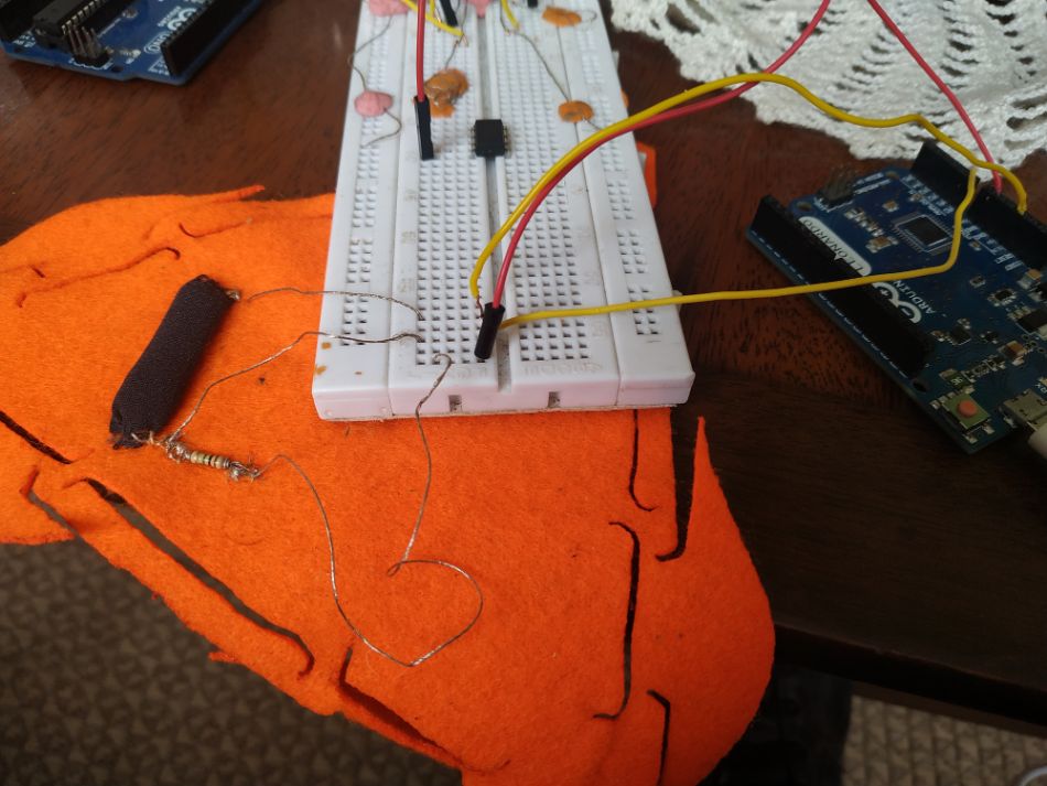
After that, we attach the wires to the already progammed chip.
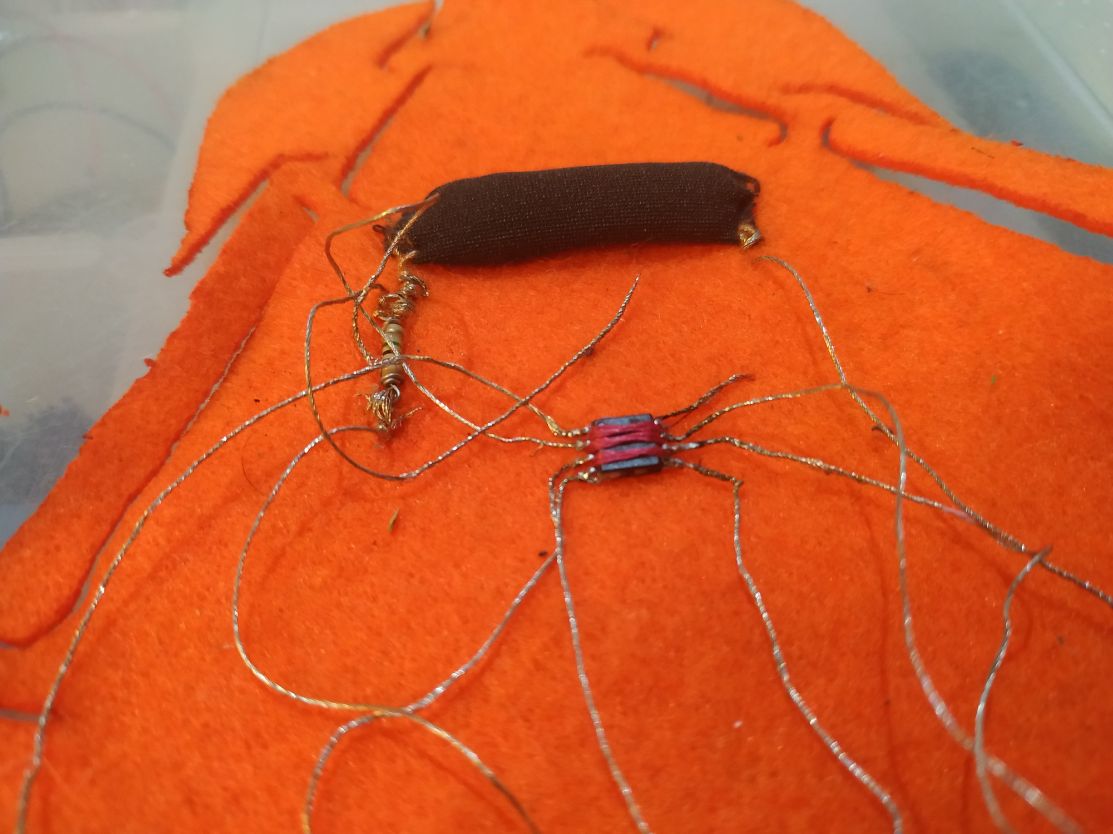
Here we can see a detail of the attachment.

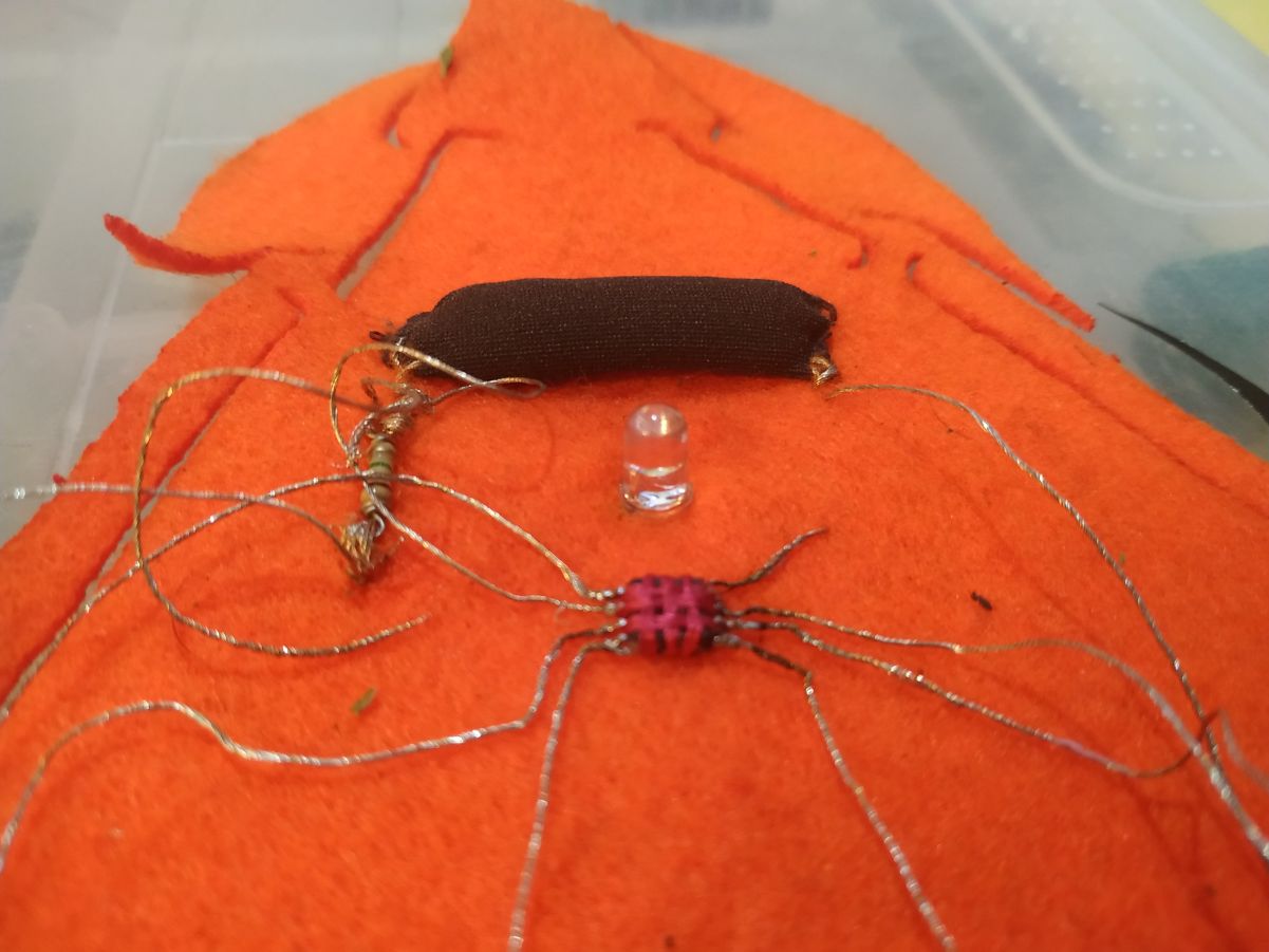
Then we add a LED and the correspondent resistor.
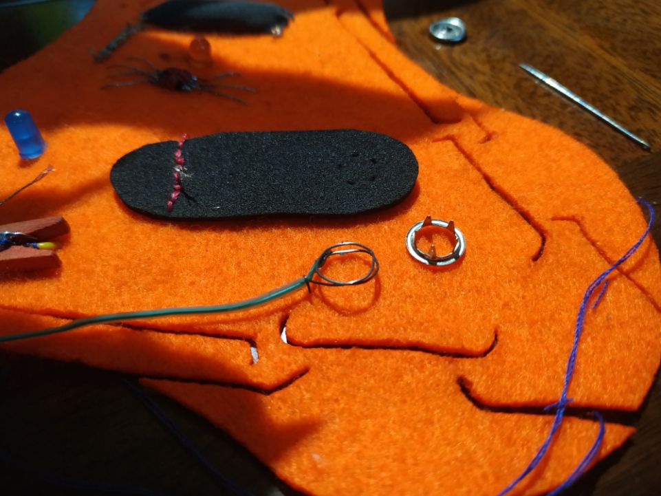
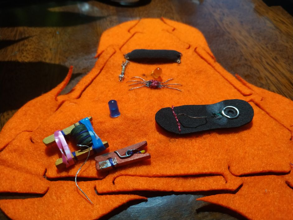
A battery holder was created. It holds four 1.5V coin batteries in series.
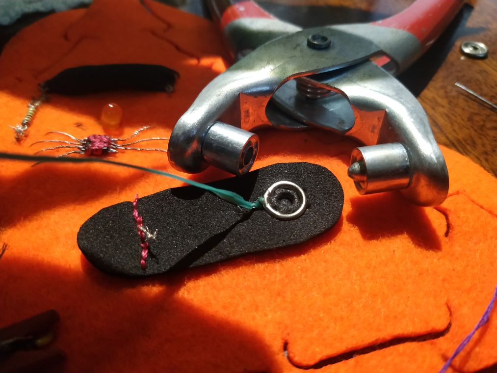
Using felt and wires we continue with the attachments. In this case I used a conductive metal attachment.
With a preassure tool, the attachment was secured in place.
Once completed, the construction provides an on-off switch.
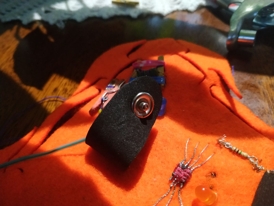
Here we can see the swatch completed.
The other side is not so pretty, but it is going to be hidden.
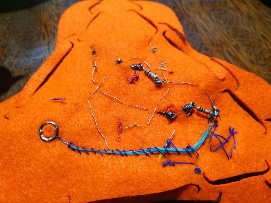
And finally, the swatch working.