This week is special, because in the middle of the week we receive a suprise from the governement and send every body home. We manage to take some things home at the last minute. What can I do home? Let see...
The input, output
- I didn't have the time to do the wearable 2 so I decide to mix both week. The skin electronic week is learning to create a flexible circut that it can take the shape of your body. Your circut need to be also isolated because we are conductive and it can mess arround with the result of your circut. It also have a security issue if your circut is near a sensitive zone like the eye for exemple. I will try to do a skin patch or something like this.
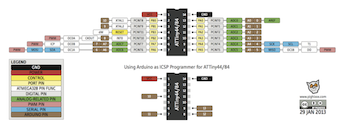
- In my material box I had some vibrators motors, an arduino, a seeduino and a UV detector light from Flora. During my fabacademy we learn how to creat small circut that combine input, output with microcontroler like Attiny 44 that we program. Here are some interesting link:
- program a ATiny 44
- design and program a board using ATiny 44 and a LED
- learning the basic of coding
- create a input and read data
- create a output with small motor
- Create a output with LED
-
So I prototype a input output first on arduino and later on I will switch it to the small seeduino.
- Base on temporary tatoo, when you go out for one complete day, you forget about your skin, so this temporary tatoo will buzz you when the UV is too intense. Using a seeduino, you can connect this tatoo to your computer and personalise the UV and the experience.
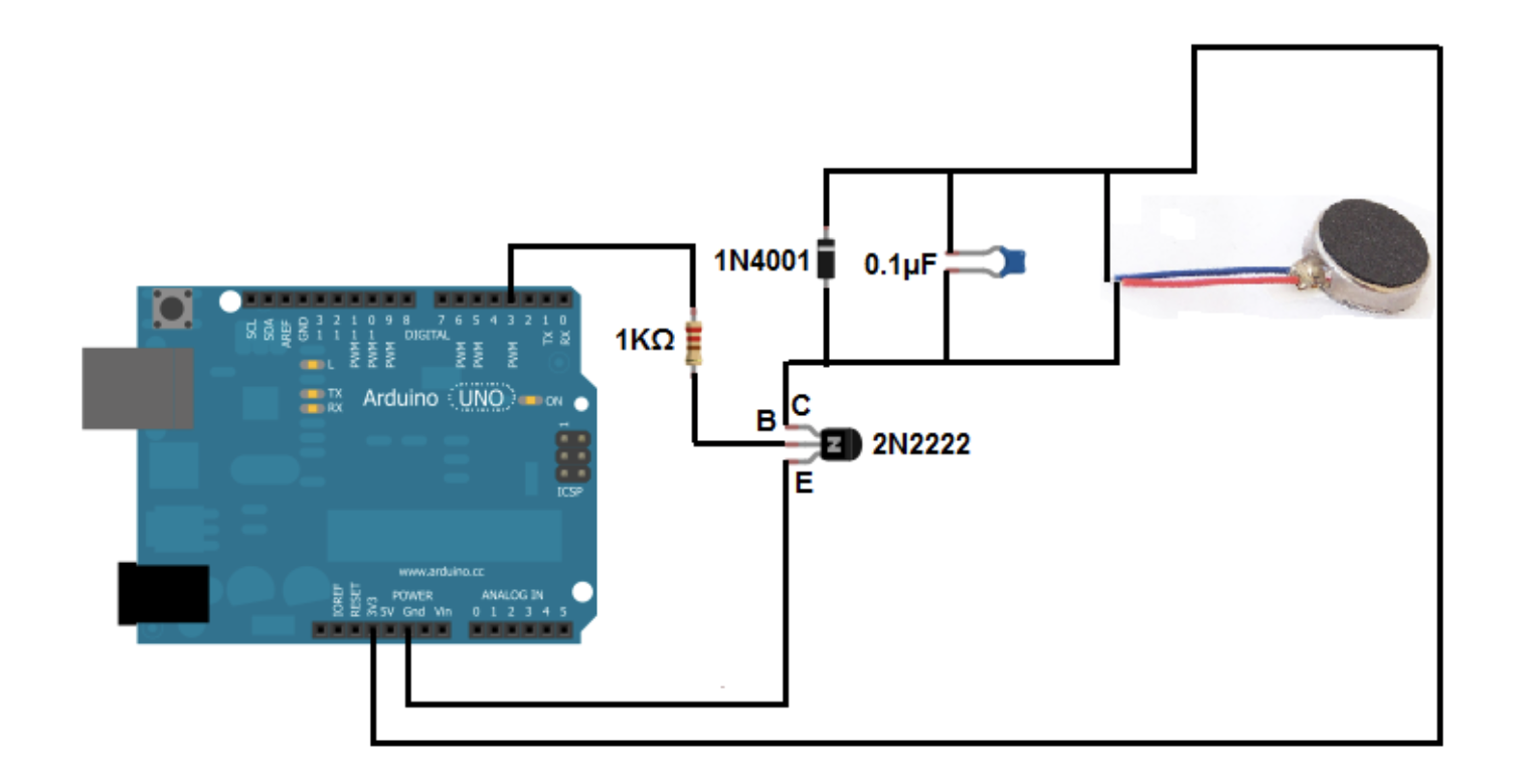
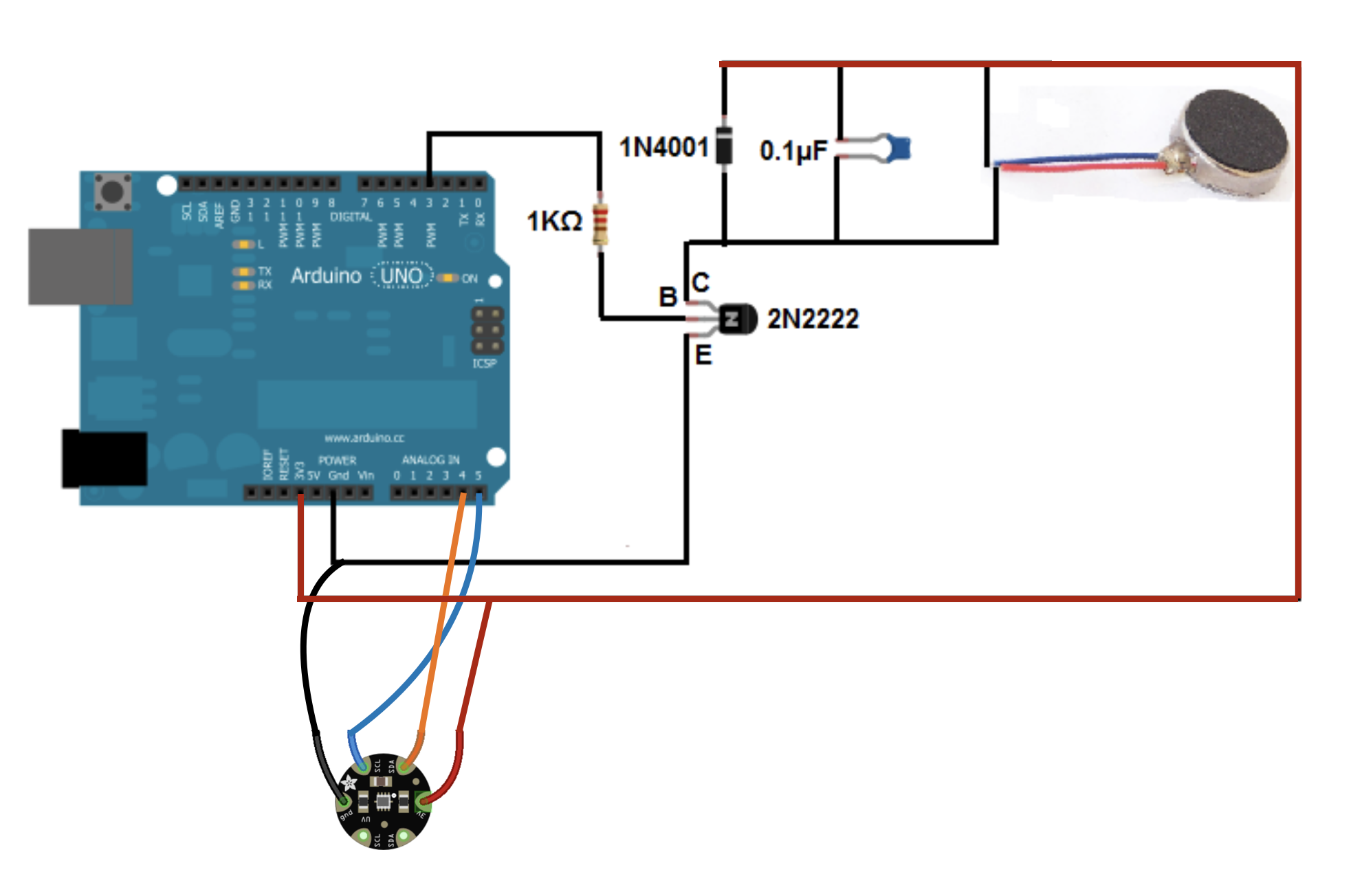
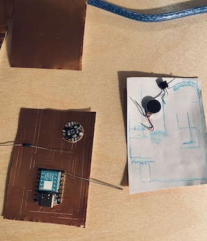
- I start by the vibrator motors. I base my circut on this web site. I test the circut on Arduino Uno and test the code. Work on the first time!!
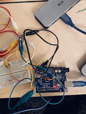
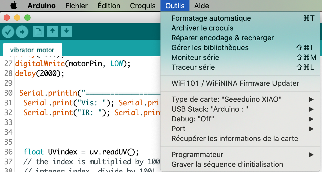
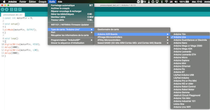
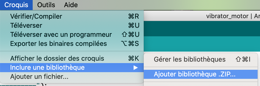
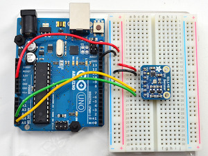
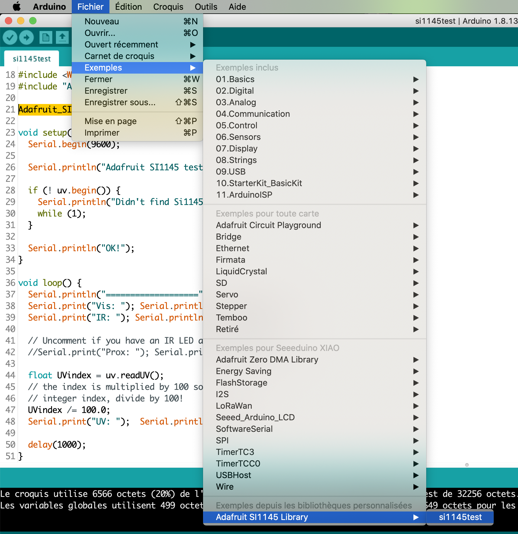
- I did the same process with the UV sensor. On an other breadboard I wire a second Arduino with the Flora UV index sensor. I base my circut on this web site. I dowload the Adafruit SI1145 library that work with the Flora UV index and add it to the Arduino IDE. (sketch, add library, open .zip) Open the exemple code for this sensor and test the breadboard circut. Work well too!
- I add both circut on the same arduino and on the same 3.3v pin and merge both code toghetter. Still work!!!
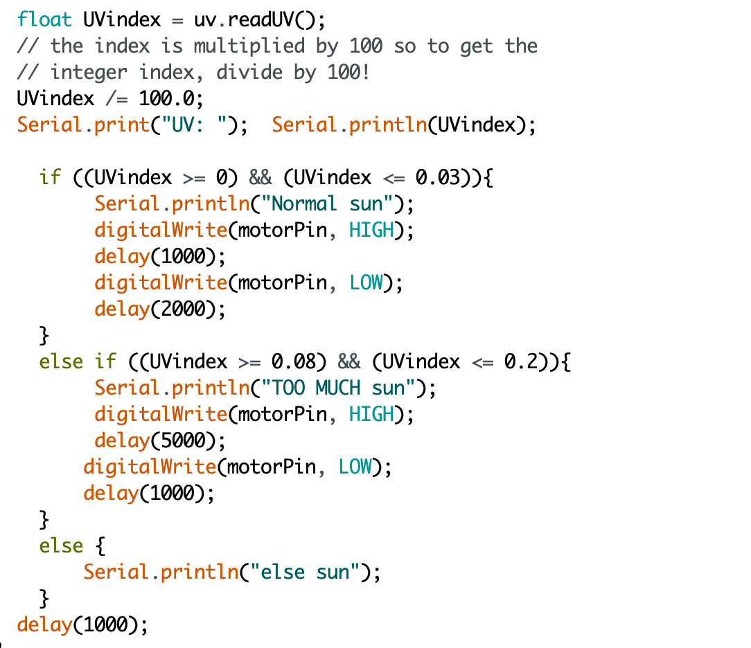
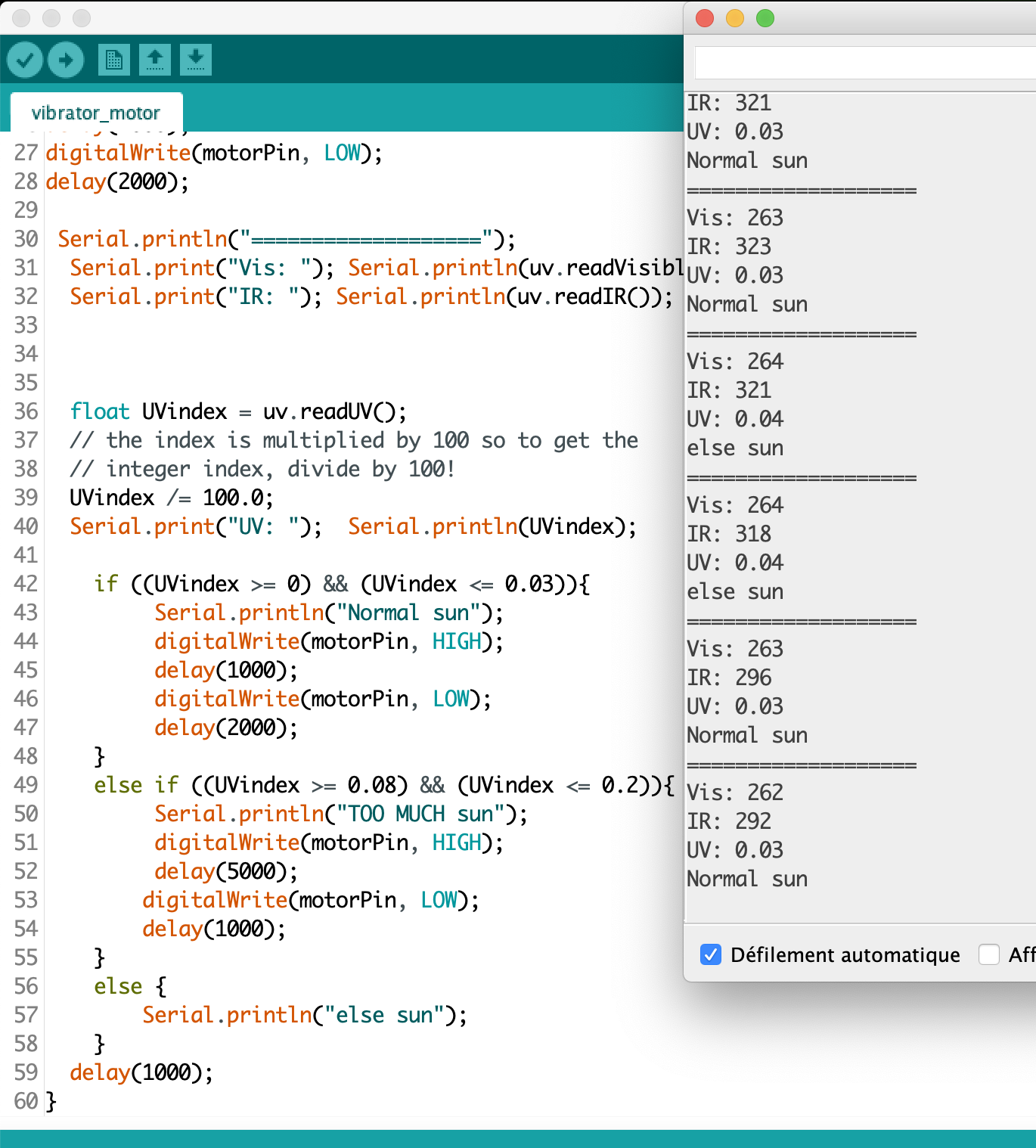
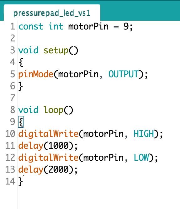
- I modify the code to make have the vibrator motor react to the UV index. I got at the basic point, 0.03 for index and when I open the light I have 0.09. I made a if, else if and else. 3 conditions that you can personalise depending if you are outside or inside.
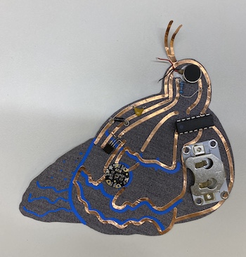
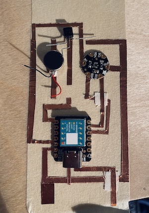
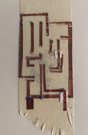
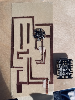
- Than I focus on making the circut. with no machine! Ok let's not panic, I have some copper tape than I can cut with scisors, and soldered after. I start by drawing the circut with a pen, than take a needle ans skratch the surface of the copper tape to mark que wire. My collegue Francois explain me that PCB where drawing by hand at the begginning.History and evolution of PCB They where drawing in big scale, (8:1 or 4:1) and with a photo graphic method they scale it to 1:1. part that was the more ambiguous was the trace near the component. I use the component has stencil.
- Cutting the copper tape and stick it on a tape to assemble everything.
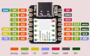
- I forgot to aliment the board for a stand alone battery 3V. The pins are on the back of the the seeduino. I have no soldering paste, I am not sure to be able to soldered these one. If it doesn't work it will alimented by USB.
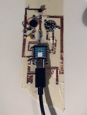
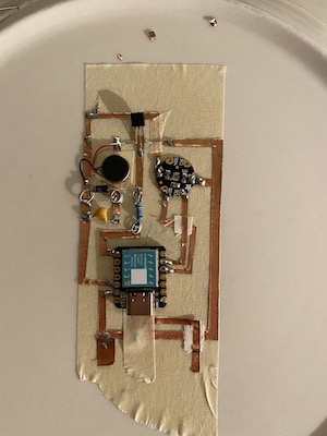
- Soldered every connection bettween the copper tape and test it with a multimeter. Soldered every component. This is not pretty, I promess I can do better. The good thing is the flexibility of the material, it's more resilient.
- I soldered everything, (exept for the baterry alimentation line to the seeduino, it's impossible with my tools right now) I test on the computer and it work well! When you use seeduino or a arduino nano for exemple, you usuely have a pin that give power (3.3v or 5V) that you can use for your components, but the alimentation of the seeduino itself is not power by that same pin. If I want to use my circut on a battery I realy need to wire the alimentation of the seeduino independantly.
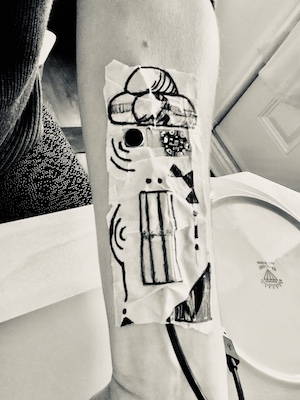
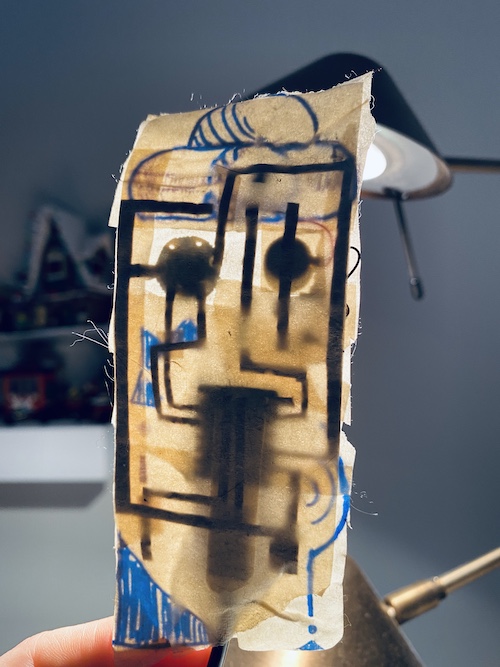
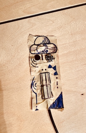
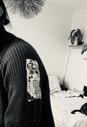
- The result of my hand cutting board is so ugly. I tape the top of it and drawing on top to create a close patch.
- Even if the circut is realy not perfect, it work realy well and event after put it on verything I can (table, arm, neck,...still work! Flexible circuit are the best! Marry Christmas to you all and stay safe.
- Here is the code.
Improving the process
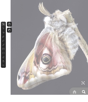
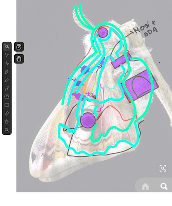
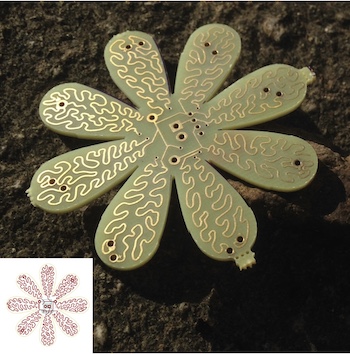
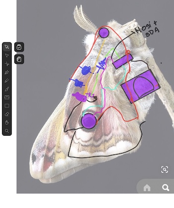
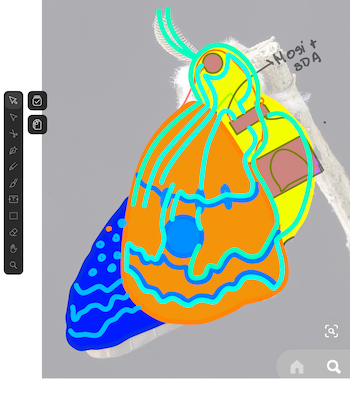
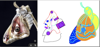
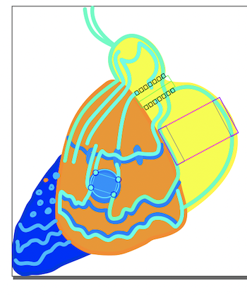
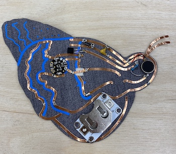
- After this experience I look on internet some exemple of art circut and I decide to try something with a virtual pen this time. I download Vectornator on my Ipad and base on a butterfly's picture, I draw some component and a circut integrated to the patern of the butterfly.
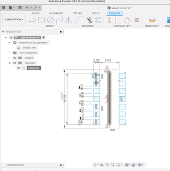
- The experience was very interesting, but the precision of the components was not precise like my previous tape experience. On Fusion 360 I create a DXF of the footprint of the component that I import in a layer in Inkscape.
- I import my drawing from my Ipad into inkscape and merge it with the dxf components to ajust que line of the circut. The good thing is you can creat 1 line with a 3mm width and at the end transform is into 2 differents vectors. It's simpler to manage the modification of only one line. In Vectormator, each time you do a line it create another vector not a continuous one. I need to be carefull about that details.
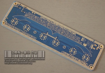
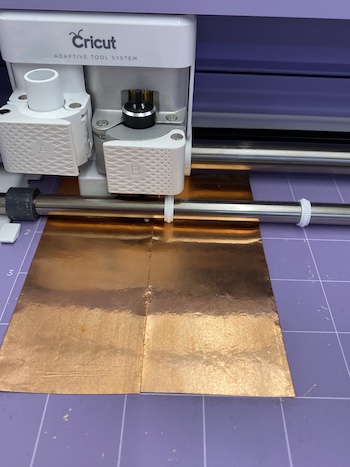
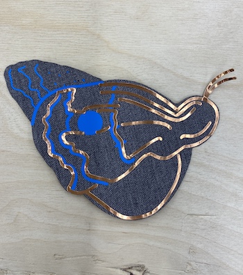
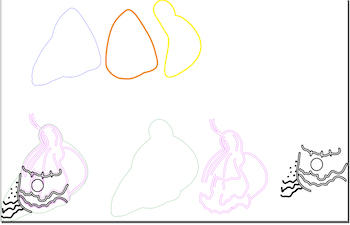
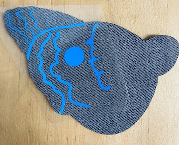
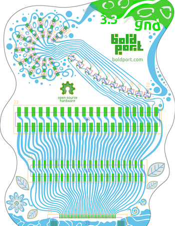
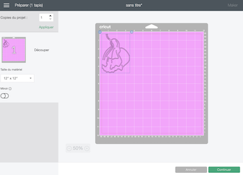
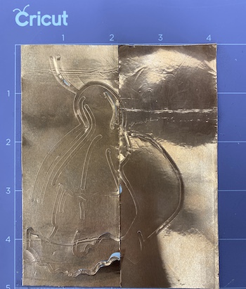
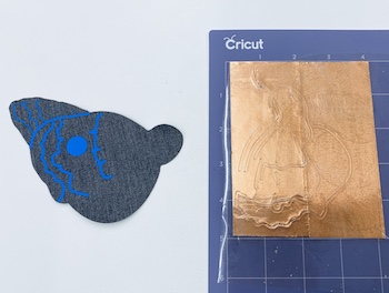
- I prepare my file for the production. I create 1 layer for the back, that will be in a gray textile cut with the laser. 1 layer in blue thermo-vinyl that will add textures and help integrate the copper circuit. 1 final layer in copper tape that I will cut with the vinyl cutter machine. My copper tape is only 2in width so I will put 2 pieces next to each other and soldered the pieces together later.
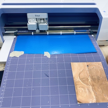
- To cut the textil I use P:40 S:1 HZ:1000. To cut the copper tape I use the parameter Adhesif foil with the cricut. I try also Metal Copper gauge 40, but it cut everything even the paper under the tape, it was a mess.
- I plan to use this time ATiny 44 to run the circut. That was a easy mistake, each time you use a library on Arduino you need to verify the compatibility with your chip. Unfortunatly for me ATiny 44 does not take the library SI1145 of my Flora lux sensor. It's a dead end. The the circut process still interesting.
- I align the the component and soldered everything in place.
- In the future I can make dxf bloc that I can import into different software, event bipmap maybe and it can be easier to create precices embrodery with technical part or different circut interegrated in weird shape.
- Here is the file