Wearables
📅This week started on November 9th with another nice presentation from Liza Stark. This week is focused on power loads = output devices = actuators
▪ What I made?
🗹 Document the concept, 3D model of the piece and document the design process
▪ Let's talk about: What does it mean to be wearable?
A wearable is going to cover our body and it turns out in our second skin so it's important that before creating the wearable you think about it and follow a design process including all the functional and human considerations
Think about: "Why do you wear it?" - "What can you express or communicate with it?"
▪ Examples
Some theory
Which is the difference between loads and power loads?? - in this case we're working with Arduino so it's important to know that the pins are not too strong to provide the correct amount of current to the different output devices. So, in this case we need something that consumes more current than the current that the Arduino can actually provide
An actuator is a component of a circuit that moves or controls another part based on an input. There are 3 types of actuators: Visual / Sound / Motion
This week I'm focusing more on sound actuators
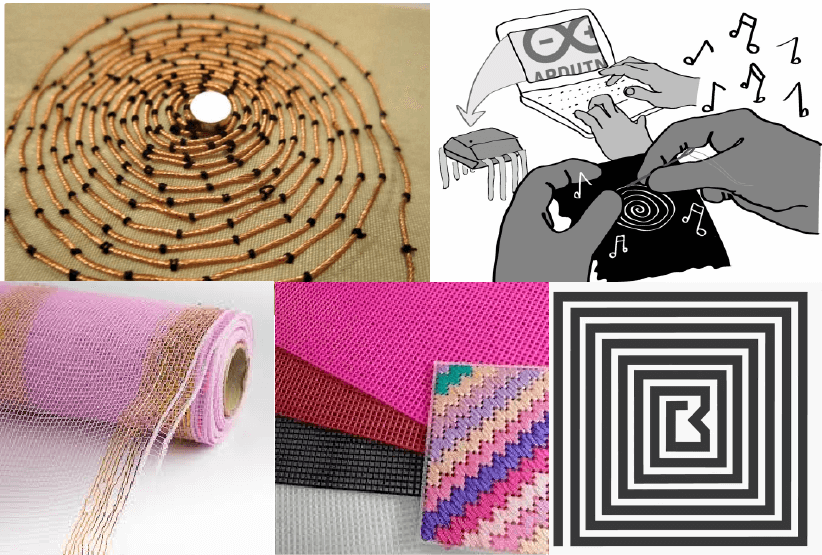
Useful resources for inspiration
This circuit is a necessary component that is able to connect the Arduino and the power load, but the power of the load is sinked by a different source.
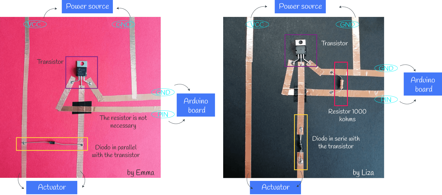
Creating the circuit
Principally, we need to use a transistor to have a secondary power source because the Arduino pins can't provide the power needed for the actuators.
Also we need one extra component: a diode to protect the transistor
There are two circuits according to the explication from Liza and from Emma, you can use either
▪ Exploring some Arduino Sketches + coils🔎
First we learned basic sketchs than can be used with other outputs devices. For this examples I used the digital sensor that I made for the week 05 and white LEDs (this are the power loads). In this part I only documented the new sketches that we didn't learn before.
▪ Counter
On the monitor serie you can see the counter, so each time that you press the digital sensor it will count 1 press. For the video I set the counter reset to 10 presses.
▪ Led on/off
This sketch works just like a traditional on/off switch. For the video I changed the code to be able to toggle both LEDs on and off.
/*
Emma Pareschi 2020
I count the times the push button is pressed
 */

// this constant won't change:
int  sw_pin = 2;    // the pin that the pushbutton is attached to
int counter_reset = 2; //variable to reset the counter

int led_pin = 3; //pin of the led 01
int led_pin2 = 5; //pin of the led 02

// Variables will change:
int counter = 0;   // counter for the number of button presses
int sw_status = 0;         // current state of the button
int last_sw_status = 1;     // previous state of the button

void setup() {
  // initialize input and output pins:
  pinMode(sw_pin, INPUT_PULLUP);
  pinMode(led_pin, OUTPUT);
  pinMode(led_pin2, OUTPUT);

  // initialize serial communication:
  Serial.begin(9600);
}

void loop() {

  // read the pushbutton input pin:
  sw_status = digitalRead(sw_pin);

  // compare the switch status to its previous state
  if (sw_status != last_sw_status) {
    if(sw_status == HIGH){     //if the status is HIGH, the switch was relaised
      counter = counter + 1;   //increase the counter of 1 unit
    }
    // Delay a little bit to avoid bouncing
    delay(50);
  }

  Serial.print("Counter: ");  //print on Serial monitor the counter value
  Serial.println(counter);

  last_sw_status = sw_status;   //set the last status

  if (counter == counter_reset){
    counter = 0;
    }

  if (counter == 0){             //if the counter is ZERO
    digitalWrite(led_pin, LOW);  //Led if off
    digitalWrite(led_pin2, HIGH);
  } else {                        //otherwise (if it is 1)
    digitalWrite(led_pin, HIGH);
    digitalWrite(led_pin2, LOW);
   }
}
▪ Array led switch
On this example you can use as many LEDs as you want to turn them on one by one in a specific order according to the programming of the code. I only tried it with two LEDs
▪ Download more sketches given by Emma Pareschi
I wanted to test the sketches with the coil (this is the new power load instead of the LEDs) but for this, theorically, it is supposed that when you apply electricity to a coil, it becomes magnet and gets attracted to a magnet, and when you remove the electricity, it does not get attracted… so I was getting deeper into this theory and I did some test to check what happens and also I experimented using different materials for the coil (have a look at this documentation from Kobakant). Also you'll need one neodymium magnet to make this tries.
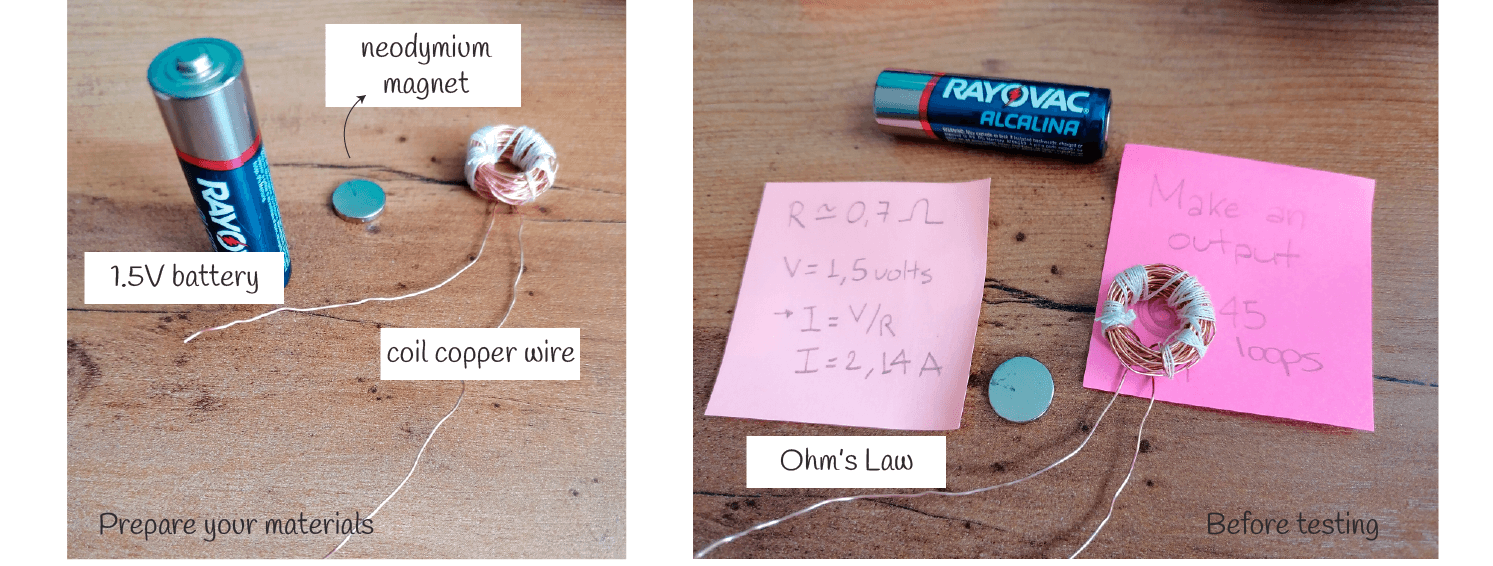
| Material | Loops | Resistance | Continuity | used Voltage | Current | Heat |
|---|---|---|---|---|---|---|
| copper thread | 45 | 0.7ohms | yes | 1.5V | 2.14A | hot! the first try made some smoke |
It's important to verify the continuity and to check the resistance of the coil. It's normal to get a very low value of the resistance. For the first try, I used a 1.5V battery and you can see that the magnet flips when the electricity goes throught the coil. This was a nice result at first time but everything was getting hot! so I disconnected it a few seconds later.
▪ Blink
First I tried with this code and it worked. Every 1000 miliseconds the magnet repels / attracts the coil. When I sewed it to the fabric it seemed to become weaker but, in fact, I think is because this thread is too heavy for the fabric so it cannot lift it a lot.
Remarks material 01: The result was not as I expected. The coil sticks to the magnet regardless of the direction of the magnet pole, but with one side it feels stronger than the other. I tried changing the +/- direction of the electricity to change the pole, as well as rotating the permanent coil and the result is the same. The coil is attracted to the magnet, but it has only 46 turns, so it takes quite a bit of current and becomes very hot quickly.
| Material | Loops | Resistance | Continuity | used Voltage | Current | Heat |
|---|---|---|---|---|---|---|
| stainless steel thread | 46 | 1.7ohms | yes | 3.3/5V | 1.2/3A | just warm, specially the transistor |
This time I didn't use an external power source because I only had a 9V battery and it would be too much for the circuit. I used the voltage from the Arduino board
I also tried with the circuit indicated by Emma but it didn't work for me, I don't know if I placed the diode with the correct orientation so I decided to use the circuit indicated by Liza.
Remarks material 02: The elements from the circuit got warm after 1 minute connected but they didn't get hot. Even this coil has only 46 loops it has a higher resistance. This coil is very week and similar to the copper thread coil.
| Material | Loops | Resistance | Continuity | used Voltage | Current | Heat |
|---|---|---|---|---|---|---|
| coil wire | 60 | 1.6 ohms | yes | 3.3/5V | 2.06/3.12A | almost warm |
For the next examples I also used the voltage from the Arduino board and some sketches from the first part
▪ Blink
▪ Button
▪ On/Off
Remarks material 03: compare to the copper thread, it is an stronger electromagnet using a little bit more current and it doesn't get as hot as the copper thread or the stainless steel thread.
▪ Exploring sound actuators 🔎
▪ Buzzer
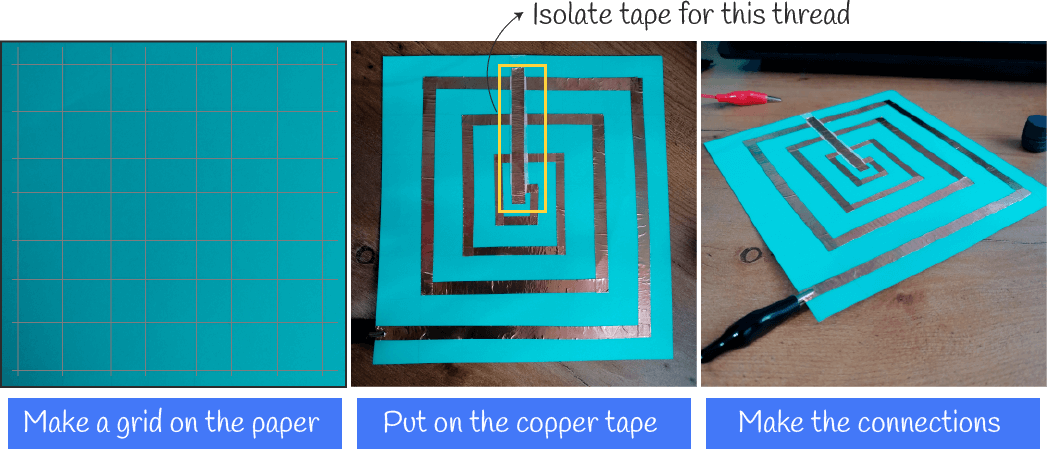
▪ Paper speaker + copper tape
| Material base | Material coil | Resistance | #loops | used Voltage | Sound | #magnets |
|---|---|---|---|---|---|---|
| Paper | copper | 9ohms | 4 | from arduino board | low | 1 |
I could only hear the sketch number 7, but the melodies and the songs I couldn't hear them using this speaker. I think there are two options to improve this one:
- More loops with the copper tape
- More closer loops (with the same 4 loops)
and of course it would be very helpful if I use more magnets because it will increase the magnetic field and the sound wil be louder.
▪ Soft speaker + stainless steel thread
| Material base | Material coil | Resistance | #loops | used Voltage | Sound | #magnets |
|---|---|---|---|---|---|---|
| Plastic | Stainless steel | 1.5ohms | 9 | from arduino board | very low | 1 |
For the last video I used the Tetris song. Find more songs here
Useful resources from Kobakant:
▪ Download more sketches for sound and also others for neopixels and more!
Outcomes and learning 📌
The actuators I liked most were the sound actuators, which I explored more. Also the first exploration with the difefrent coils was really helpul to achieve a good speaker but I think it would be better to have more magnets to get a louder sound. It will be nice two try another option conecting the speaker to another device like the cellphone.
Findings for improving
▪ Its a low cost DIY that allows to make lots of garments
▪ The grid could be 3d printed
▪ there're lots of patterns for the coil and it can be embroidered with some nice designs
Limitations
▪ Sound is directly proportional to the strenght of the magnet
▪ It takes too much time to knit all the plastic grid
▪ Tone function from arduino can't be used with more than one speaker at the same time
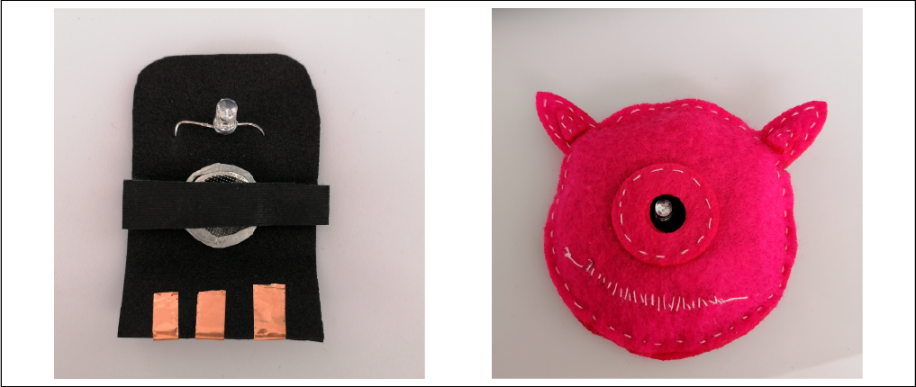
▪ LED RGB for creating a monster
On monday 15th we follow a tutorial from Nuria Robles and learned to make an interactive monster. This was a nice workshop to learn how to create a monster using a circuit for the RGB LED.
I was not happy with this switch soo I made another one that works better but I don't know why the blue leg is still having some problems because it's kind of tricky to get that color. But okay, finally I sewed my little monster and here is the final result.
Download Rhino and Grasshopper file for the monster
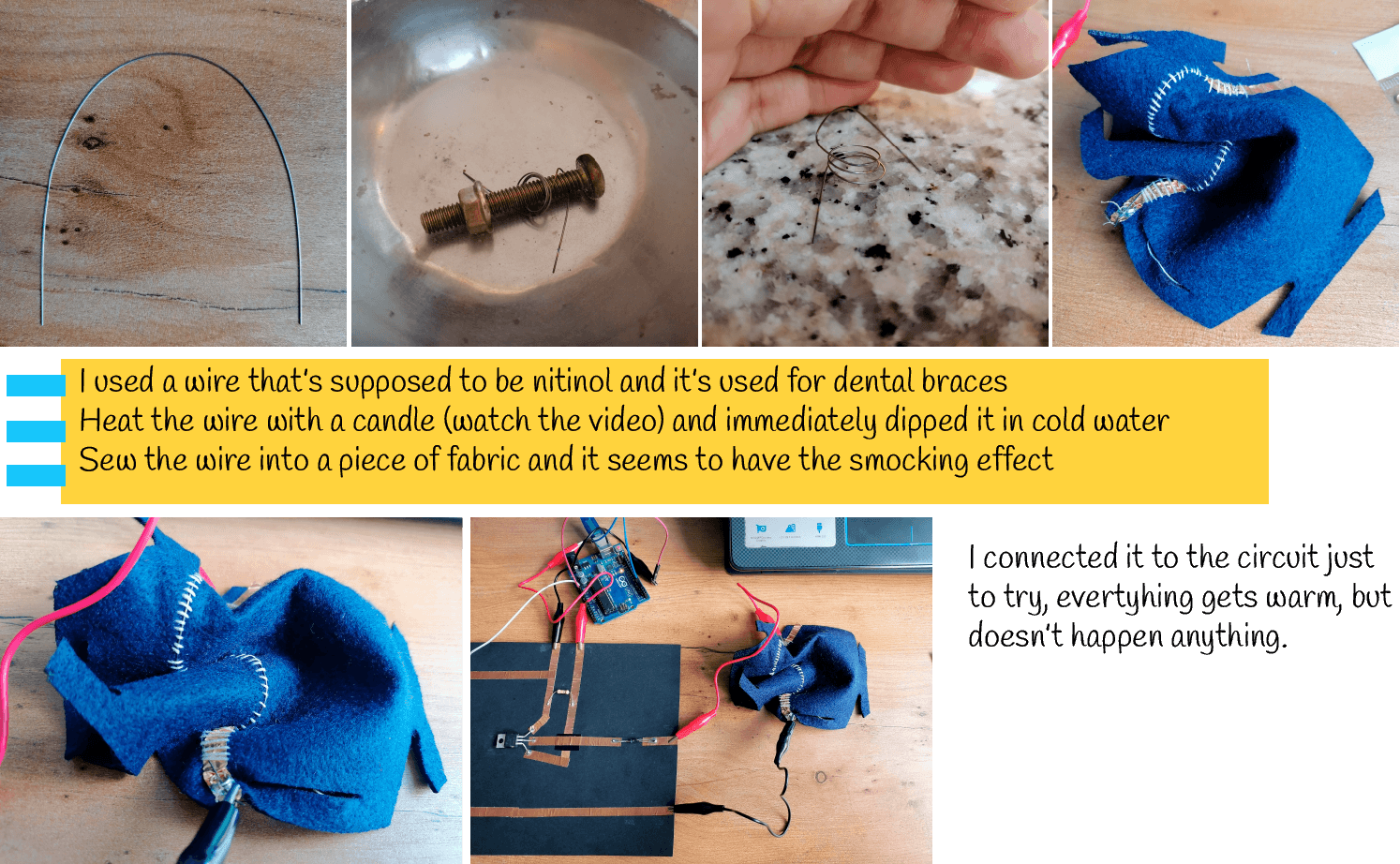
▪ Fake nitinol
This part is quite funny because I only got one very short wire of something used in dental braces that is supposed to be nitinol so I tried with it.
I based my work on the example of Lyza but she used trained Flexinol which is another muscle wire used for this type of actuators. Also at SMA meets Smocking (from an e-textile Summercamp) you'll find more about Smocking technique and the development of samples with diverse Smocking patterns that can be useful for you.
| Material | SMA training | Resistance | Continuity | used Voltage | Current |
|---|---|---|---|---|---|
| Nitinol (or not) | yes (kind of) | 1.6 ohms | yes | N/A | N/A |
Useful resources from Kobakant:
▪ Shape Memory Alloy Connection