Extensive Documentation
▪ Electronic Architecture
I started looking for the sensors that can be useful for my project. I need a sensor that measures the temperature of my neck when it gets rush. I found that there are two options: (1) the contact sensor and (2) the non-contact sensor. Here're some main differences:
| Parameter | Advantages & Disadvantages |
|---|---|
| Accuracy: | Generally contact sensors are considerably more accurate than IR thermometers |
| Response Time: | IR thermometers are faster responding than contact thermometers – almost instant |
| Distance: | IR thermometers have a great accuracy until 3cm in front of the object and probe thermometers need to be in touch with the surface |
1. Temperature sensor with contact
In this group I found two sensors that are widely used for sensing and are very easy to get, they are also fairly affordable in price. One of them is the DHT11/DHT22 which I will dismiss because it is not very useful for measuring a surface in contact. And the other one is the LM35 sensor, this is one of the most used when you need a fast and easy to assemble sensor.
LM35
Main features
One of the great features of the LM35 temperature sensor is that it's linear and this means that a change of temperature in the sensor causes a voltage change in its output (which is proportional to a constant). An increase of 1ºC causes an increase of 10mV in the output voltage. For example, if the temperature is 25ºC at the sensor output we will obtain 250mv. If it increases to 26ºC the output voltage will increase to 260mv.
The fabricant (Texas Instruments) claims that the sensitivity is almost constant (10mV/ºC) and that its "non-linearity" is ±0.2ºC. This is good for applications such as measuring the temperature of a room, but it's the same good for measuring my skin?. The nice fact that it is linear and low tolerance saves us from having to calibrate and obtain probe calibration curves. Just plug and start.
with LM3914? https://www.youtube.com/watch?v=5fQ7IFsIaiU&ab_channel=Wvargascel
with attiny85? https://www.instructables.com/IR-Thermometer/
with LM3915? https://www.youtube.com/watch?v=4CDbTDdCgcs&ab_channel=IvanEspinoza
with Arduino Nano? https://www.youtube.com/watch?v=bvByHY_-8YQ&ab_channel=SriTuHobbyTech
2. Temperature sensor without contact
⚠️This is just for general knowledge about this other type of sensor that at first I was planning to use
I found that the MLX90614 infrared thermometer from Melexis measures the temperature without contact (it actually measures the radiation produced by our body). The molecules of our body are constantly moving, producing radiation that is not visible to our eyes, but this sensor is able to detect that infrared radiation emitted by our body. In short, the higher the temperature of the body, the faster the molecules move and there is more radiation. Therefore, the sensor detects it and translates it into degrees (°C). But how does it do it? First, by converting the radiation into electricity and then a temperature value is calculated.
Specifically the MLX90614 is a family of infrared thermometers with 3 different models that differ mainly by the temperature range they can measure and the accuracy of measurement. In this case, the accuracy I don't think is something very important for the application I need, for example, a BAA model supports a temperature range from -40ºC to 125ºC for the ambient temperature and from -70ºC to 380ºC for the temperature on the surface of objects. This model is enough to detect the radiation from my neck and translate it into electricity to turn on the lights. The operating voltage of the MLX90614 BAA model is between 2.6V and 3.6V. Recommended to feed directly with a voltage of 3V (can be a coin battery). It is compatible with arduino boards and microcontrollers attiny85.
▪ Temperature Sensor Distance Range
LM35 - Contact sensor
▪ Usage
The lm35 temperature sensor theoretically drains 56μA when it is around 25°C and around 91μA when it approaches its upper and lower extremes.
▪ Measuring with the sensor
As the output of the lm35 sensor is a voltage proportional to temperature we can verify if the temperature sensor is working properly using a simple multimeter in voltmeter configuration. Simply connect the sensor power to 5volts and GND to ground. We connect the GND to ground and the voltage test lead to the sensor output.
▪ Measure temperature with LM35 sensor
The video below shows the values of the 2 -out pin from the sensor, this are the values before transforming them into temperature units.
▪ Measuring temperature with arduino
The temperature needs to be calculated taking into account that every 10 mv from 0v represents 1 degree Celsius. In void loop we use the instruction -> float temperature = (analogRead(A0) * 500) / 1024. The first thing is to convert the reading from 0 to 1024 of the ADC to millivolts, we do this with a simple rule of three, and finally we divide by 10 to get the value in ºC.
The code looks like this:
// this is the initial code just to make sure the conections with
// the sensor are working and to configure the tool settings for the arduino nano

void setup (){
  // put the setup code here, to run once:
pinMode (A0, INPUT); //read you input from the analog pin
Serial.begin(9600); //put the bits per second
}

void loop (){
  // put the main code here, to run several times:
int data=analogRead(A0); //to read the value from the analog port
int temperature=data*(500.0/1024.0); //create an equation to read in serial monitor (celsium degrees from the ambient)
Serial.println(temperature); //print the result of the equation
}
▪ Turning On the LEDS with the sensor
First I made the conections for the sensor in Tinkercad, this time I followed a tutorial on youtube, which is this equation for the values of the temperature: float c=(valor-102)/2. I wrote that code to simulate the the lighting of the LEDs. I placed there 4 blue LEDs with 4 resistors of 1k ohm. For this you can use the code below.
int valor=0; //create a variable asignned with value 0
void setup()
{
Serial.begin(9600); //put bits per second
}

void loop()
{
    valor=analogRead(A0); //to read the value from the analog port
  float c=(valor-102)/2; //create an equation to read in serial monitor (degress from the ambient)
  Serial.print("temperature:");//the name "temperature"
  Serial.println(c);//print the result of the equation

  if(c<15){ //if tempertaure in celcium degrees is less than 15,the LED from this PIN wil turn on
    digitalWrite(5,HIGH);
    }else{
    digitalWrite(5,LOW);
    }

    if(c>=16 && c<25){ //if tempertaure in celcium degrees is less than 30 but higher than 16,the LEDs from this PIN wil turn on
    digitalWrite(5,HIGH);
    digitalWrite(4,HIGH);
    }else{
    digitalWrite(5,LOW);
    digitalWrite(4,LOW);
    }

      if(c>=26){ //if tempertaure in celcium degrees is less than 30 but higher than 16,the LEDs from this PIN wil turn on
    digitalWrite(5,HIGH);
    digitalWrite(4,HIGH);
    digitalWrite(3,HIGH);
    }else{
    digitalWrite(5,LOW);
    digitalWrite(4,LOW);
    digitalWrite(3,LOW);
    }

      if(c>=36){ //if tempertaure in celcium degrees is less than 30 but higher than 16,the LEDs from this PIN wil turn on
    digitalWrite(5,HIGH);
    digitalWrite(4,HIGH);
    digitalWrite(3,HIGH);
    digitalWrite(2,HIGH);
    }else{
    digitalWrite(5,LOW);
    digitalWrite(4,LOW);
    digitalWrite(3,LOW);
    digitalWrite(2,LOW);
    }
 }
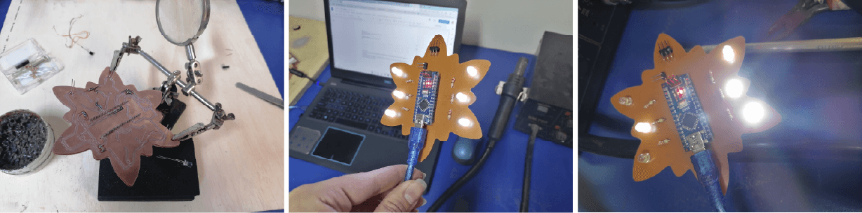
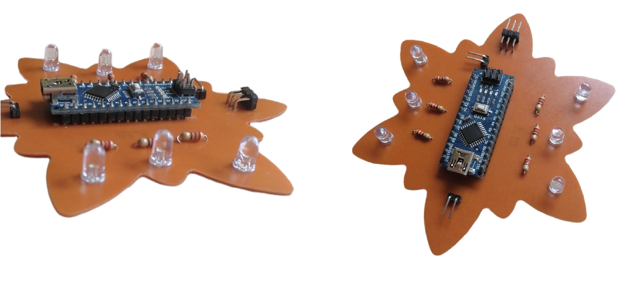
After that I started to explore with the sensor and the code in real. The first step was to choose the number of LEDs and the value of the resistors. Also I'm using an Arduino Nano, this board is based on the ATmega328 microncontroller so this will be useful for the next steps of making a PCB. My shape for the neck piece is kind of a flower and kind of an star and I want to put a white LED on each end. So, assuming my star/flower has 6 points, that would be 6 LEDS.
The digital pins of the Arduino can have two states: high (HIGH) or low (LOW). If we insert a LED in the circuit we must be careful how we insert it, because the LED is an electrical component (Ligth Emitting Diode) that allows current flow in only one direction. The current always goes from higher potential to lower potential, that means that, if wI connect the circuit to 5V (we can get the 5 volts from the USB port of our laptop) and the other end I connect it to ground 0V, the current will flow from 5V to 0V.
On the datasheet of a typical LED you'll find this: **Forward Voltage (Vf). The Foward Voltage will depend on each LED, it's the voltage that the LED will consume when it is on. It indicates the recommended values for its good performance. White LEDs need 3.3 V and 20 mA to turn on and work with all of it's brigthness, those have a Vf = 3.5V . According to that I decided to use a parallel circuit because it's more efficient to have the same voltage for the 6 LEDs and split the current in the circuit. The issue here is that this circuit will consume more current so the voltage of the power supply will run out much faster than in a serial circuit. The minimum current required by most white LED types at the above voltage is 10 mA, 20 mA being the optimal range, however these devices are able to operate even with 40 mA of current, producing dazzling brightness.
Considering Kirchhoff's Voltage Law, we must do something with that 5V so that when it reaches the LED it is no longer 5V, it should be the recommended 3.3V. At this point Ohm's Law comes into play. This law tells us that V=R*I. What I am interested in is to know what resistor should be used to consume the excess voltage. Therefore I used the formula R=V/I or you can calculate it directly at OHMs Law calculator
The only thing missing is to know how much current the Arduino board is giving us. As the LED is going to be connected to a digital pin, if we look at the technical characteristics of the Arduino nano, the current (DC Current per I/O Pin) will be 40mA. Therefore, I must calculate the voltage I want that resistor to use, if I have 5V and the LED is going to consume 3.3V, the resistor should consume the 1.7V left over for Kirchhoff's Law to be fulfilled. Considering that the maximum current that can be drawn from an Arduino nano when powered externally (Jack or VIN and GND pins) is 500mA, however, the total amperage combined from the Input/Output pins (including the analog pins) of the Atmega328 micro controller must never exceed 200 mA. So, if I were using ten outputs to 10 LEDs and each of them at 20 mA, this would already reach the limit when turning on all 10 LEDs. But I am only using 6 LED outputs with 20 mA each.
With a 42.5 Ω resistor I would be within the recommended range. To make the LED shine brighter, I can change the value of this resistor, for example go up to 3.5V (this is the maximum recommended for white LEDs), which implies that the resistor will have to use less voltage and therefore will be smaller.
But I was skeptical about this result as I had seen circuits with several LEDs using 1 k ohm resistors or 330 ohms, so why did I get this value of 45 ohms? After some other understandings and tutorials I found this other calculator really useful. The thing is that I need those 45 Ω for the whole circuit, as if it were a single LED, but I have a parallel circuit with 6 resistors (one per each LED) so, I need to calculte the value of the resistance of the parallel circuit.
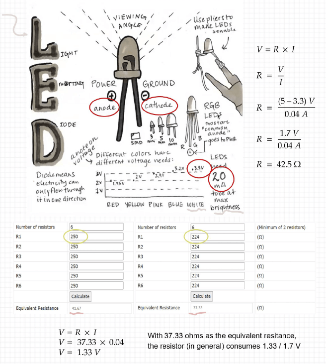
Finally I'm using 6 resistors of 224 ohms because I got those at the lab and I saw it wasn't really necessary to buy the resistance of the exact amount.
| # LEDs | # Resistors |
|---|---|
| 6 white LEDs | 6 resistors - 224 ohms |
▪ White LED Power Supply Design Techniques
▪ Tutorial Basic Electronics - Emma Pareschi
▪ Tutorial Basic Electronics - Sparkfun
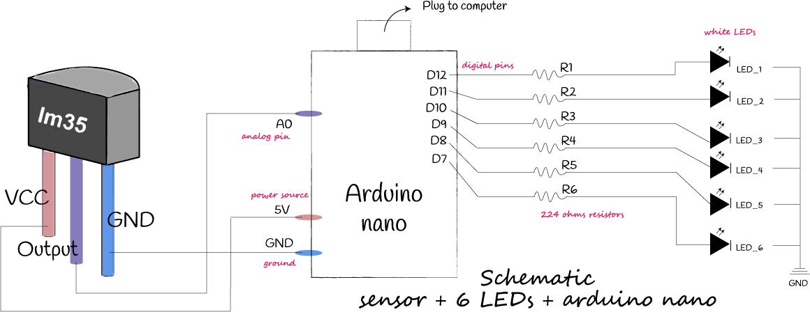
With that I made the schematic before building my prototype:
// this code is to turn on the LEDs using the sensor and the arduino nano
int data=0;
// define each LED you want to use and the digital pin from the arduino
#define LED_1 12 // LED 1 with digital pin 12
#define LED_2 11 // LED 2 with digital pin 11
#define LED_3 10 // LED 3 with digital pin 10
#define LED_4 9 // LED 4 with digital pin 9
#define LED_5 8 // LED 5 with digital pin 8
#define LED_6 7 // LED 6 with digital pin 7

void setup()
{
  // put the setup code here, to run once:
pinMode(LED_1, OUTPUT);
pinMode(LED_2, OUTPUT);
pinMode(LED_3, OUTPUT);
pinMode(LED_4, OUTPUT);
pinMode(LED_5, OUTPUT);
pinMode(LED_6, OUTPUT);
Serial.begin(9600); //put bits per second
}

void loop()
{
  // put the main code here, to run several times:
  int data=analogRead(A0); //to read the value from the analog port
  float temperature=data*(500.0/1024.0); //create an equation to read in serial monitor (celsium degrees from the ambient)
  Serial.print("temperature:");//print the result of the equation
  Serial.println (temperature);
  delay(0);
  // create the conditions to turn on the LEDs

  if(temperature<=15){ //if tempertaure in celcium degrees is less than 15, LED1 wil turn on
    digitalWrite(LED_1,HIGH);
    }else{
    digitalWrite(LED_1,LOW);
    }

    if(temperature>=16 && temperature<22){ //if tempertaure in celcium degrees is less than 30 but higher than 16,LED1 & 2 wil turn on
    digitalWrite(LED_1,HIGH);
    digitalWrite(LED_2,HIGH);
    }else{
    digitalWrite(LED_1,LOW);
    }

      if(temperature> 23 && temperature<30){ //if tempertaure in celcium degrees is less than 30 but higher than 26,LED 1, 2 & 3 wil turn on
    digitalWrite(LED_1,HIGH);
    digitalWrite(LED_2,HIGH);
    digitalWrite(LED_3,HIGH);
    }else{
    digitalWrite(LED_1,LOW);
    digitalWrite(LED_2,LOW);
    }

      if(temperature> 31 && temperature<35){ //if tempertaure in celcium degrees is less than 36 but higher than 16,LED 1, 2 , 3 & 4 wil turn on
    digitalWrite(LED_1,HIGH);
    digitalWrite(LED_2,HIGH);
    digitalWrite(LED_3,HIGH);
    digitalWrite(LED_4,HIGH);
    }else{
    digitalWrite(LED_1,LOW);
    digitalWrite(LED_2,LOW);
    digitalWrite(LED_3,LOW);
    }

       if(temperature> 36 && temperature<40){ //if tempertaure in celcium degrees is less than 36 but higher than 16,LED 1, 2 , 3 ,4 & 5 wil turn on
    digitalWrite(LED_1,HIGH);
    digitalWrite(LED_2,HIGH);
    digitalWrite(LED_3,HIGH);
    digitalWrite(LED_4,HIGH);
    digitalWrite(LED_5,HIGH);
    }else{
    digitalWrite(LED_1,LOW);
    digitalWrite(LED_2,LOW);
    digitalWrite(LED_3,LOW);
    digitalWrite(LED_4,LOW);
    }

          if(temperature>=41){ //if tempertaure in celcium degrees is less than 36 but higher than 16,LED 1, 2 , 3 ,4 , 5 & 6 wil turn on
    digitalWrite(LED_1,HIGH);
    digitalWrite(LED_2,HIGH);
    digitalWrite(LED_3,HIGH);
    digitalWrite(LED_4,HIGH);
    digitalWrite(LED_5,HIGH);
    digitalWrite(LED_6,HIGH);
    }else{
    digitalWrite(LED_1,LOW);
    digitalWrite(LED_2,LOW);
    digitalWrite(LED_3,LOW);
    digitalWrite(LED_4,LOW);
    digitalWrite(LED_5,LOW);
    }
 }
▪ Some issues
Everything seamed to be running perfectly, I dind't have problems with the resistors I chose, but the first thing I noticed is that the LED_1 was not working properly. I checked my connections in the breadboard again but there was any mistake with the wires or the legs of the LEDs.
I was placing the jumper in the row in front of the digital pin 12 but the LED didn't turn on, only when the jumper was in touch directly with the D12 the LED was working! So fuzzy but then I changed this PIN and now the LEDS have another pin assigned:
// define each LED you want to use and the digital pin from the arduino
#define LED_1 6 // LED 1 with digital pin 6
#define LED_2 11 // LED 2 with digital pin 11
#define LED_3 10 // LED 3 with digital pin 10
#define LED_4 9 // LED 4 with digital pin 9
#define LED_5 8 // LED 5 with digital pin 8
#define LED_6 7 // LED 6 with digital pin 7
The next thing I noticed was that the temperature I was getting from the sensor was kind of high, I mean, it was late at nigth and the "ambient temperature" couldn't be 50 - 60 celcium degrees. So, I guess it was because the sensor was placed in the breadboard really close to the LEDs (But really not sure about it).
I decided to connect the sensor with some alligator clips, in this way the sensor is no longer placed directly over the breadboard, so here comes the third discovery, I started to place the sensor over my neck (my neck was not blushing or hot because I was quite calm) and the values of the temperature were round the 24-26 degrees, so it seems to be normal. Buuut... I noticed that:
-
There's a delay! When the temperature reached the LED 4 (like 30 degrees) and then the temperature dicreased (to 24-26 degrees) there was a time-lapse with turn off LEDS.
-
It's difficult to detect the change of the temperature with the ranges I'm handleling. I also tried with fire very close to the sensor and in that case the difference of values is more remarkable because the degrees can reach to 70 - 80.
-
A wrong connection can make an increase in the output of the sensor. Even when I bumped some cables the sensor was going crazy.
This is the "issue" of the delay. The LEDs take about 3 or 4 seconds to turn on again, depending on the temperature. Maybe I need to change the logic of the code? Well, I just added the delay(10) to the void loop, so basically reducing the delay will reduce this time lapse for the LEDs to turn ON again but I don't know if it is useful for me now o not, I'll decide later.
This video is before adding the delay change:
// this is the initial code just to make sure the conections with
// the sensor are working and to configure the tool settings for the arduino nano
float temp;
int pinLM35=0;
void setup (){
  // put the setup code here, to run once:
Serial.begin(9600); //put the bits per second
}

void loop (){
  // put the main code here, to run several times:
 temp=analogRead(A0);// read the sensor
 temp=(5.0 * temp * 100.0)/1024.0; //create an equation to read in serial monitor (celsium degrees from the ambient)
Serial.println(temp); //print the result of the equation

delay (10); //time to repeat the loop
}
I wanted to incorporate a button, because I don´t want to start reading the values from the sensor once I connect it to VCC. So I used my digital sensor from week 03 and looked for the code to program that sensor as a push button and use it a a toggle switch. It mean, that once I press the button, the temperature sensor will start reading the temperature and the lights will turn on,but when I hit the button again everything will stop working and the code stops. To make this I look at this tutorial that is really well explained.
// constants won't change. They're used here to set pin numbers:

const int ledPin_1 =  6;// the number of the LED pin
const int ledPin_2 =  7;
const int ledPin_3 =  8;
const int ledPin_4 =  9;
const int ledPin_5 =  10;
const int ledPin_6 =  11;
const int buttonPin = 13;// the number of the pushbutton pin

// variables will change:
int ledState=0;
int buttonState;// variable for reading the pushbutton status
int buttonOld=1;
float temp;
int dt=100;//delay time

void setup() {
  Serial.begin(9600); //put the bits per second
  // initialize the LED pin as an output:
  pinMode(ledPin_1, OUTPUT);
  pinMode(ledPin_2, OUTPUT);
  pinMode(ledPin_3, OUTPUT);
  pinMode(ledPin_4, OUTPUT);
  pinMode(ledPin_5, OUTPUT);
  pinMode(ledPin_6, OUTPUT);

  // initialize the pushbutton pin as an input:
  pinMode(buttonPin, INPUT);//I'm reading from that pin
}

void loop() {
  // read the state of the pushbutton value:
buttonState = digitalRead(buttonPin);
if (buttonOld==0 && buttonState==1){
    if (ledState==0){//indicating the LED is off
     // turn LED on:
        ledState=1;
temp=analogRead(A0);// read the sensor
temp=(5.0 * temp * 100.0)/1024.0; //create an equation to read in serial monitor (celsium degrees from the ambient)
Serial.println(temp); //print the result of the equation

    if (temp>=20 && temp<23){
    digitalWrite(ledPin_1, HIGH);}

else{
  if (temp>=23.01 && temp<26){
    digitalWrite(ledPin_1, HIGH);
    digitalWrite(ledPin_2, HIGH);}

    if (temp>=26.01 && temp<29){
    digitalWrite(ledPin_1, HIGH);
    digitalWrite(ledPin_2, HIGH);
    digitalWrite(ledPin_3, HIGH);}

    if (temp>=29.01 && temp<32){
    digitalWrite(ledPin_1, HIGH);
    digitalWrite(ledPin_2, HIGH);
    digitalWrite(ledPin_3, HIGH);
    digitalWrite(ledPin_4, HIGH);}

    if (temp>=32.01 && temp<35){
    digitalWrite(ledPin_1, HIGH);
    digitalWrite(ledPin_2, HIGH);
    digitalWrite(ledPin_3, HIGH);
    digitalWrite(ledPin_4, HIGH);
    digitalWrite(ledPin_5, HIGH);}

    if (temp>=35.01 && temp<38){
    digitalWrite(ledPin_1, HIGH);
    digitalWrite(ledPin_2, HIGH);
    digitalWrite(ledPin_3, HIGH);
    digitalWrite(ledPin_4, HIGH);
    digitalWrite(ledPin_5, HIGH);
    digitalWrite(ledPin_6, HIGH);}
}

}
else
{
    digitalWrite(ledPin_1, LOW);
    digitalWrite(ledPin_2, LOW);
    digitalWrite(ledPin_3, LOW);
    digitalWrite(ledPin_4, LOW);
    digitalWrite(ledPin_5, LOW);
    digitalWrite(ledPin_6, LOW);
  ledState=0;
}
}
buttonOld = buttonState;
delay(dt);
}
I made the toogle switch but it was not perfectly working because I press once and the sensor reads the temperature of that moment and the corresponding lights turn on, buuuut the sensor doesn't continue reading. Then, I press again the button and it stops reading, so in fact this button works but the sensor is not measuring the temperature until I hit the button twice. So sad :c
I asked Emma some tips to fix that because I tried making some changes by myself but it kept working on that way. Emma made some changes to the code.
⬇️ Here is the final code
// constants won't change. They're used here to set pin numbers:

const int ledPin_1 =  6;// the number of the LED pin
const int ledPin_2 =  7;
const int ledPin_3 =  8;
const int ledPin_4 =  9;
const int ledPin_5 =  10;
const int ledPin_6 =  11;
const int buttonPin = 13;// the number of the pushbutton pin

// variables will change:
float temp;
int buttonState;// variable for reading the pushbutton status
boolean measure=false;
int buttonOld=1;
int dt=100;//delay time for the pushbutton

void setup() {
  Serial.begin(9600); //put the bits per second
  // initialize the LED pin as an output:
  pinMode(ledPin_1, OUTPUT);
  pinMode(ledPin_2, OUTPUT);
  pinMode(ledPin_3, OUTPUT);
  pinMode(ledPin_4, OUTPUT);
  pinMode(ledPin_5, OUTPUT);
  pinMode(ledPin_6, OUTPUT);

  // initialize the pushbutton pin as an input:
  pinMode(buttonPin, INPUT);//I'm reading from that pin
}

void loop() {
  // read the state of the pushbutton value:
  buttonState = digitalRead(buttonPin);

  if (buttonState != buttonOld){
    if(buttonState == HIGH){
      measure =! measure;
      delay(100);
    }
  }

  if (measure==true){ //indicating the LED is off

      Serial.println("start to measure");
      temp=analogRead(A0);// read the sensor
      temp=(5.0 * temp * 100.0)/1024.0; //create an equation to read in serial monitor (celsium degrees from the ambient)
      Serial.print("temperature: "); Serial.println(temp); //print the result of the equation

      if (temp>=20 && temp<23){

          digitalWrite(ledPin_1, HIGH);

        } else if (temp>=23.01 && temp<26){

          digitalWrite(ledPin_1, HIGH);
          digitalWrite(ledPin_2, HIGH);

        } else if (temp>=26.01 && temp<29){

          digitalWrite(ledPin_1, HIGH);
          digitalWrite(ledPin_2, HIGH);
          digitalWrite(ledPin_3, HIGH);

        } else if (temp>=29.01 && temp<32){

          digitalWrite(ledPin_1, HIGH);
          digitalWrite(ledPin_2, HIGH);
          digitalWrite(ledPin_3, HIGH);
          digitalWrite(ledPin_4, HIGH);

        } else if (temp>=32.01 && temp<35){

          digitalWrite(ledPin_1, HIGH);
          digitalWrite(ledPin_2, HIGH);
          digitalWrite(ledPin_3, HIGH);
          digitalWrite(ledPin_4, HIGH);
          digitalWrite(ledPin_5, HIGH);

         } else if (temp>=35.01 && temp<38){

            digitalWrite(ledPin_1, HIGH);
            digitalWrite(ledPin_2, HIGH);
            digitalWrite(ledPin_3, HIGH);
            digitalWrite(ledPin_4, HIGH);
            digitalWrite(ledPin_5, HIGH);
            digitalWrite(ledPin_6, HIGH);}

         } else {
            //Serial.println("Stop measure.");
            digitalWrite(ledPin_1, LOW);
            digitalWrite(ledPin_2, LOW);
            digitalWrite(ledPin_3, LOW);
            digitalWrite(ledPin_4, LOW);
            digitalWrite(ledPin_5, LOW);
            digitalWrite(ledPin_6, LOW);

        }

  buttonOld = buttonState;
  delay(dt);
}
Notes and Warnings
The statements that are beign evaluated inside the control structure require the use of one or more operators shown below
x = y (x is has an specific value that is "y")
x == y (x is equal to y)
x != y (x is not equal to y)
x <  y (x is less than y)
x >  y (x is greater than y)
x <= y (x is less than or equal to y)
x >= y (x is greater than or equal to y)
⬇️ Here are some links that helped me to understand the changes that Emma did.
▪ Control structure for Arduino IDE
▪ Youtube - Estructura de Control Condicional
By the way, I found this Arduino Workshop for Beginners that may be useful for more than one in some of the weeks during Fabricademy
▪ Power Source
At this point I think I'm done with the code so it's time to start thinking in the "hardware part". First of all: How this system can be independent?
One of the most important parts when facing a project with Arduino or any microcontroller is how we are going to feed it and in case you have to use batteries which battery power is going to use to have autonomy. But it is not only about powering Arduino, we must take into account that we're feeding through the microcontroller the sensor and actuators or outputs and if we do not take into account the electrical limitations of the microcontroller, we can find that the project doesn't work.
Here are some of the most common methods used for powering a project:
▪ USB Power
▪ Variable DC Benchtop Power Supply
▪ AC to DC Wall Adapter (like a computer or laptop would use)
▪ Batteries (the best for wearables). The capacity of a battery is usually rated in ampere-hours (Ah) or milliampere-hours (mAh), and it tells you how many amps a fully charged battery can supply over a period of one hour.
I have an ATmega 328 microcontroller that draws about 40 mA and I connected 6 white LED’s and the 224 ohm current limiting resistors to digital I/O pins of the microcontroller. In that configuration, each LED added makes the circuit draw about 20mA more current. Now I also connected the temperature sensor that draws about 60uA (0.06 mA)
The total possible current draw is = 40 mA + 6 x 20 mA + 0.06 mA = 160.06 mA (0.164006 A)
A LiPo battery may be the best power source I can choose. Specially because I have a parallel circuit so I don't need too much voltage but I need a lot of current (almost the total current from the microcontroller). At the end I used a 9V battery because I didn't get the LiPo and this power source was working just fine for my circuit.
Useful Links
▪ How to power a project - sparkfun
▪ Baterías para alimentar arduino
▪ Shield
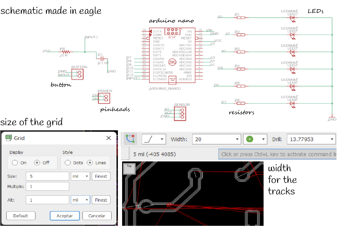
For this part I used Eagle from Autodesk that is a powerful tool for designing printed circuit boards. After downloading the software is necessary to start with some configurations:
Project 📂
In documents > Eagle > project
▪ Save the schematic and the board in a folder you'll remember because those documents are important
▪ Save the documents often so you don't lose anything
Libraries 📂
In documents > Eagle > libraries
▪
▪
Then you can start with the schematic, some notes and recommendations:
▪ It is better to have a wire coming out of each pin and label that wire with a tag. This makes it easier to make any changes without having to disconnect and reconnect the wires.
▪ The led I am using is 5mm, the negative legs (the shorter ones) are connected to GND and the positive ones (the longer ones) are connected to the resistors.
▪ I am using pinheads to connect the wires (for the button, the power supply and for the sensor)
▪ I need one more resistor and a 10uF capacitor to avoid the "bounce" that the button may have
▪ Don't forget to check how the pinhead connections are when connecting the sensor wires and others
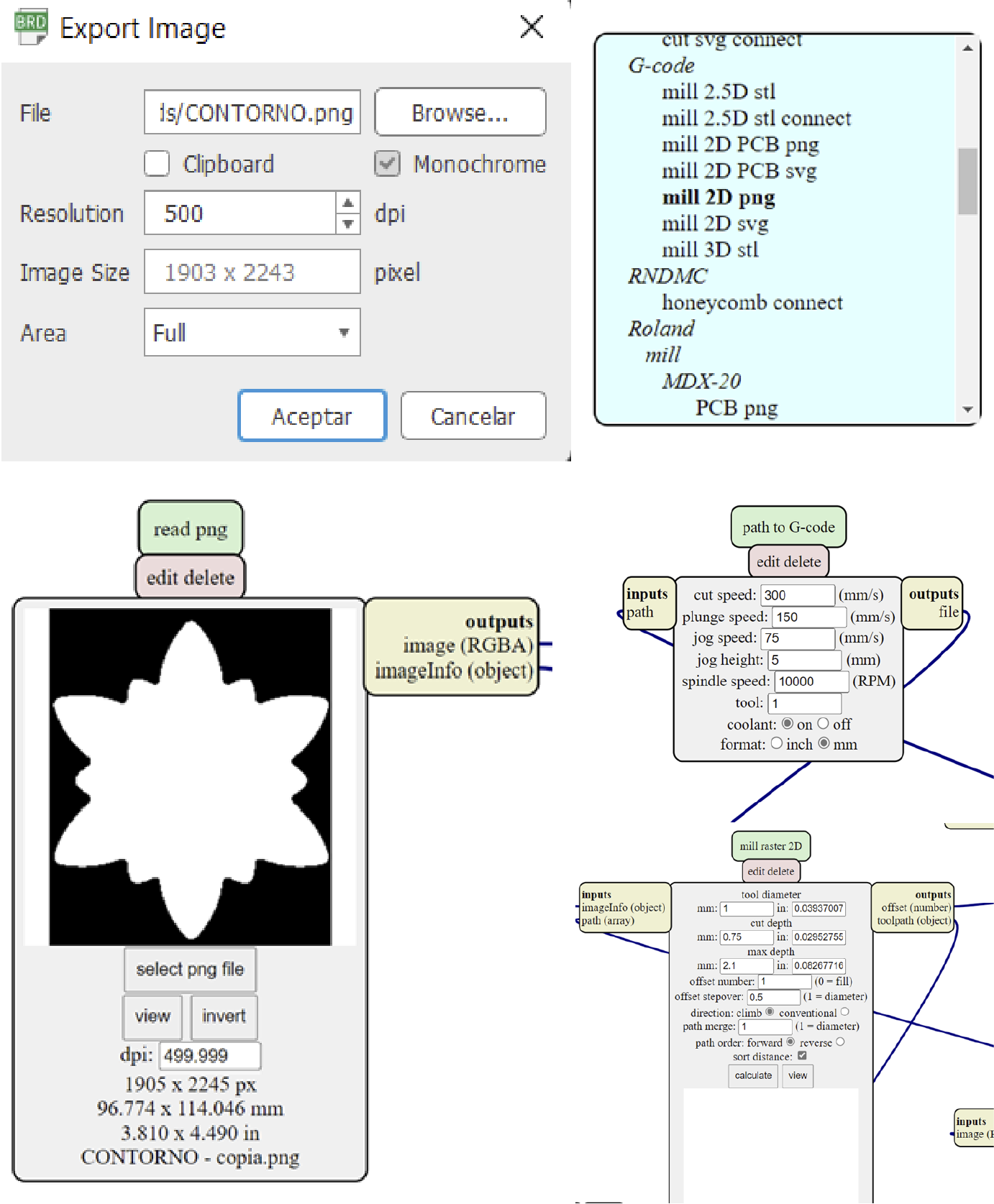
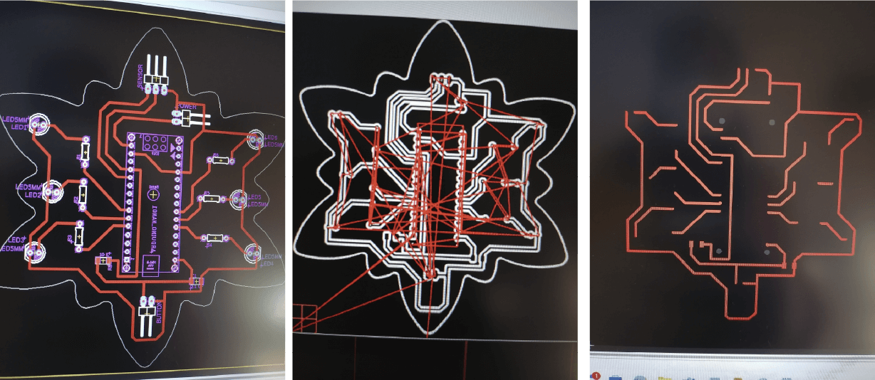
After that, I started with the board, this wil be the desing for the board I'm going to mill.
Some notes and recommendations:
▪ It's better to work with a small mesh (between 1 and 5 mil) to be able to move the tracks easily
▪ Tracks can be a minimum of 20 mil (not too thin because when machining you can lose the tracks). Larger tracks are for larger cables that have higher loads and those don't allow the board to burn easily
▪ I must mirror the components that have green circles (in this case I only mirrored the Arduino; the LEDs and resistors are not a problem because I can orient them when soldering)
▪ In the copper part there shouldn't be any element left (that is why the mirror should be made). On the board the " box" is shown as if I were looking at the PCB with the copper side up (because that is where the tracks are made)
▪ The pinhead orientation is important because it tells me how I am going to connect the wires
▪ To measure the total area (bounding box) I must change the grid to millimeters. (To continue making the tracks change it back to mil)
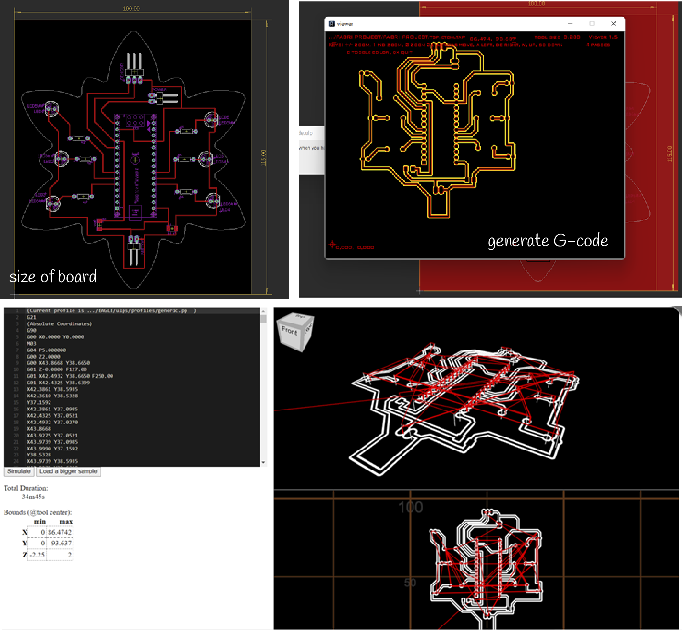
▪ It's better to use the tracks at 90 degrees and not to make very long tracks. There should be a distance about 4 or 5 mm between the tracks and the edges of the shape. Don't leave one track too close to the other because they could get lost when machining
Prepare work station and learn about the machine
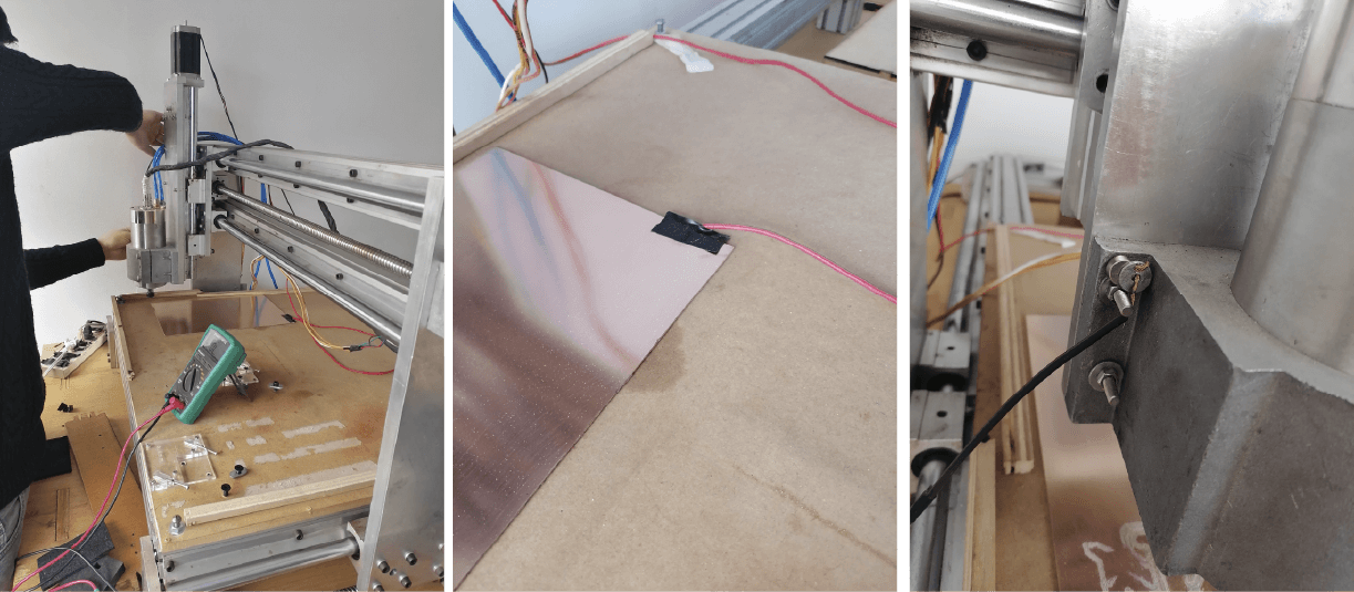
First try
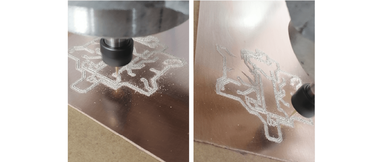
Fixing some paths
This was de hardest part because I made so many mistakes while soldering
Emergency 🆘
after my big soldering challenge, it was time to test it and unfortunately the sensor was not working properly. On the screen it showed the sensor working but the values did not make the lights turn on and even though I changed the code several times I could not get it to work properly. I didn't want to spend more time testing the sensor again so I decided not to use it until I knew how to fix it another time. Too bad 😥
I was about to do my last test just with the lights and the button and I realized that something was wrong with one of the lights. So I decided to check what happened but I didn't disconnect the circuit from the power (please never do that) and it burned some traces! Even sadder! 😥
The good part is that it was the leads that connected to the sensor so I was able to continue using the rest.
Relief
I had no other option than soldering some wires on the front of the case, right on the arduino. That way I could connect to GND and close the circuit to turn on the lights. These were my last minute adjustments before I started recording the video and the other stuff for the final presentation. Maybe those wires don't look very good but it's working! 😊