Skin Electronics
The final week 😯 This week started on Monday 6th (I made this assignment after the final project though) with the recitation from Filippo Nassetti who showed us amazing projects about generative bodies, Biodigital prostheses and so on. It's interesting this connection between the future, the human body and nature 👀 and mostly of his works were 3d printed with digital techniques that makes them beautiful and functional.
▪ What I made?
🗹 Document the concept, sketches, references also to artistic and scientific publications
🗹 Design a skin circuit: Build an interactive tattoo / skin touchpad
🗹 Document the project and included all files and all materials used
🗹 Make a video with your skin electronic working
▪ Let's talk about: Skin
What does it mean to have a skin? For me the skin is a large and big beautiful packaging that shows the the individual's condition (when we're happy, worried, sick, etc) and also protect us thanks to the receptors it has.
Some Possibilities:
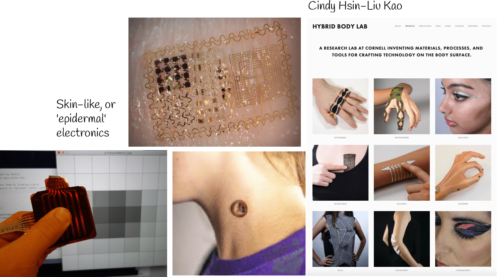
Beauty Technology - how can we make it more interactive or extend our skin? How we can personalize even more our skin? Let's call it a second skin
Epidermal Electronics - for medical applications mostly. Soft, skin-like electronics consist of thin, elastic membranes that laminate onto biological tissues in a minimally invasive manner, with long-term biocompatibility. An example is in epidermal devices that gently, but intimately, integrate with surface of the skin, where they provide clinical-quality measurements of physiological health status in a continuous fashion, without the need for conventional hospital apparatus.
Useful links to know more about 📚
▪ Recitation Postnatural Design by Filippo Nassetti
▪ Skin Electronics by Katia Vega
▪ References
▪ Learning Attiny
Emma Tutorials of Attiny: Part 1 - Part 2 - Part 3
Materials/Components
▪ jumpers + breadboard + alligator clips
▪ arduino UNO + USB cable
▪ LEDs + resistors + capacitor 10uF
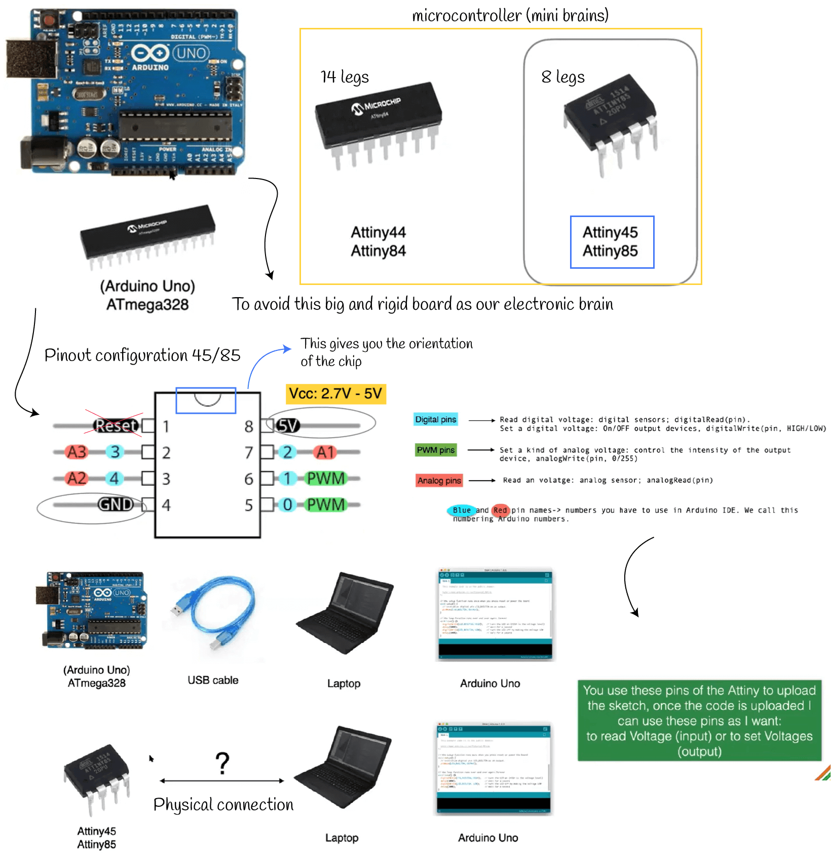
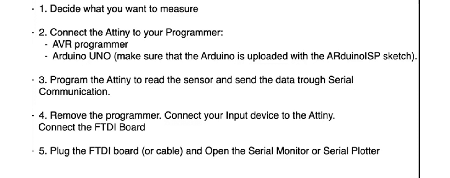
Transform Arduino UNO in programmer
-
Use ArduinoISP example, don't change the sketch
-
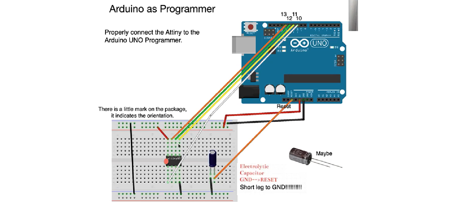
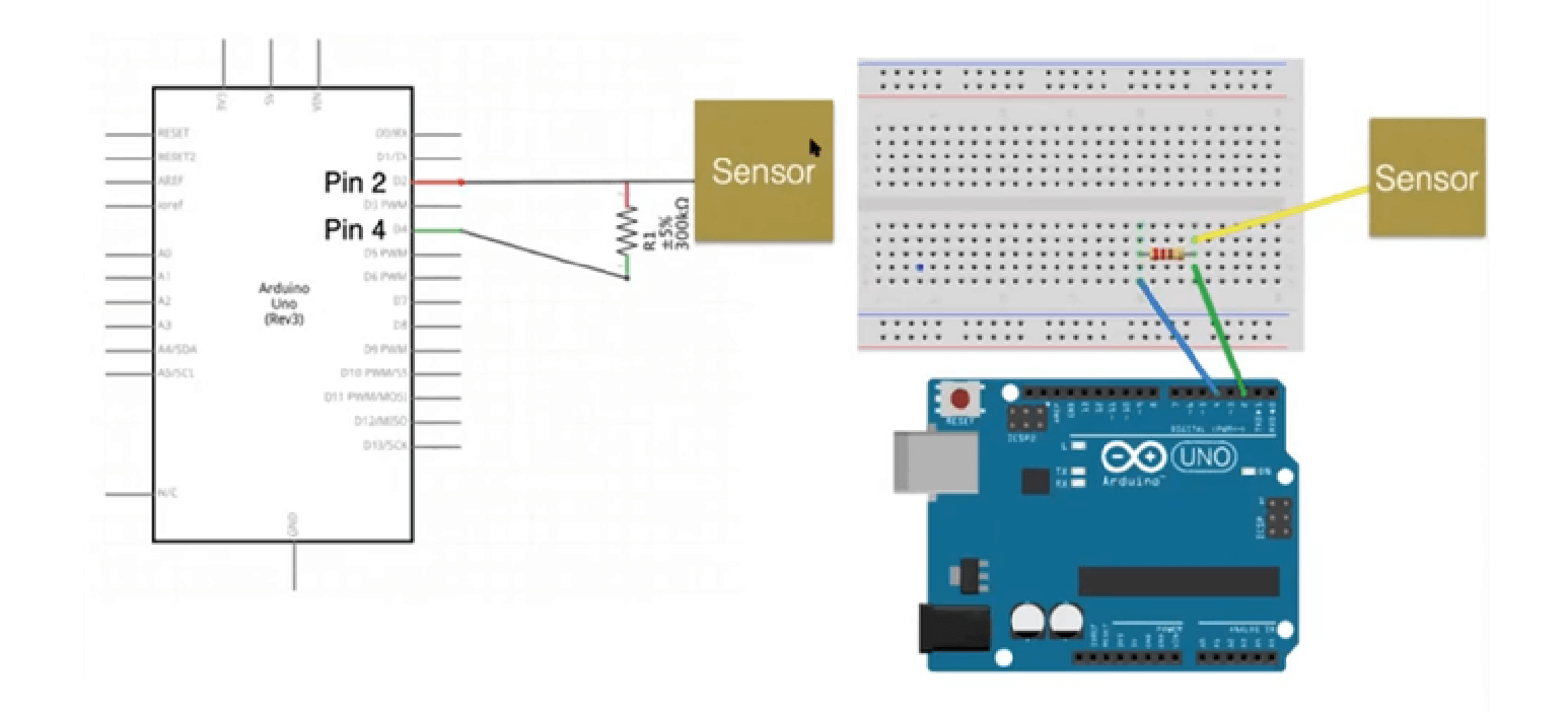
Now, Arduino Uno is ready, but is missing the pyshical connection with the ATtiny. Here are the connections ⬇️
Arduino IDE set up
Follow this tutorial
- Install the attiny board on the preference settings
- Install attiny at the Board Manager
- Now you have the attiny microcontrollers in the boards from the topl section
- Arduino IDE is ready
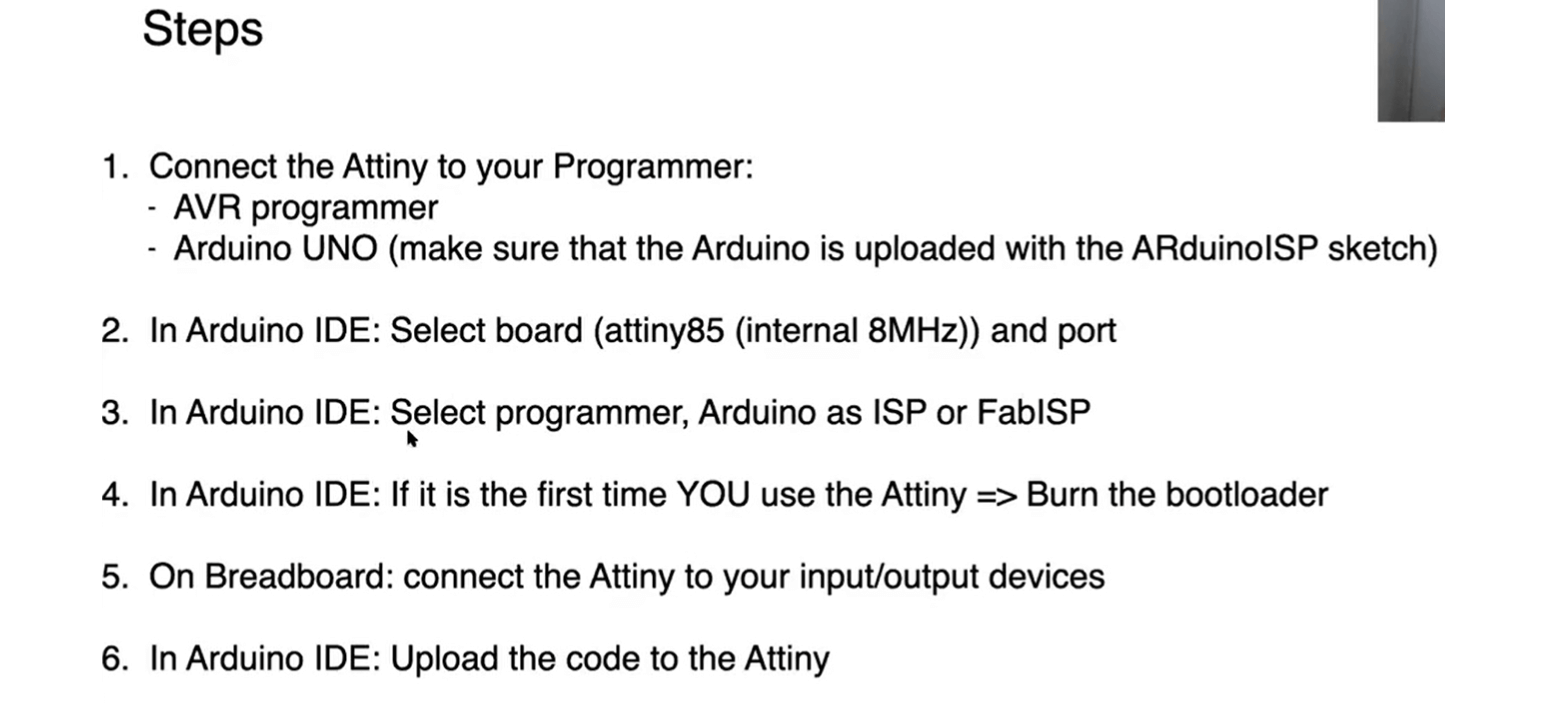
Burn the bootloader
As I'm using for the first time this ATtiny that I just bought, I followed this steps:
- Select the rigth board/processor and the internal clock of 8MHz
- Select the rigth programmer: Arduino as ISP
- Plug the Arduino UDE
- Tools > Burn Bootloader
- ATtiny is ready to use!
Program the attiny! The goal is have a blinking LED
Blinking LED with Arduino UNO
Blinking LED without Arduino UNO
Blinking LED + digital sensor with Arduino UNO
Blinking LED + digital sensor without Arduino UNO
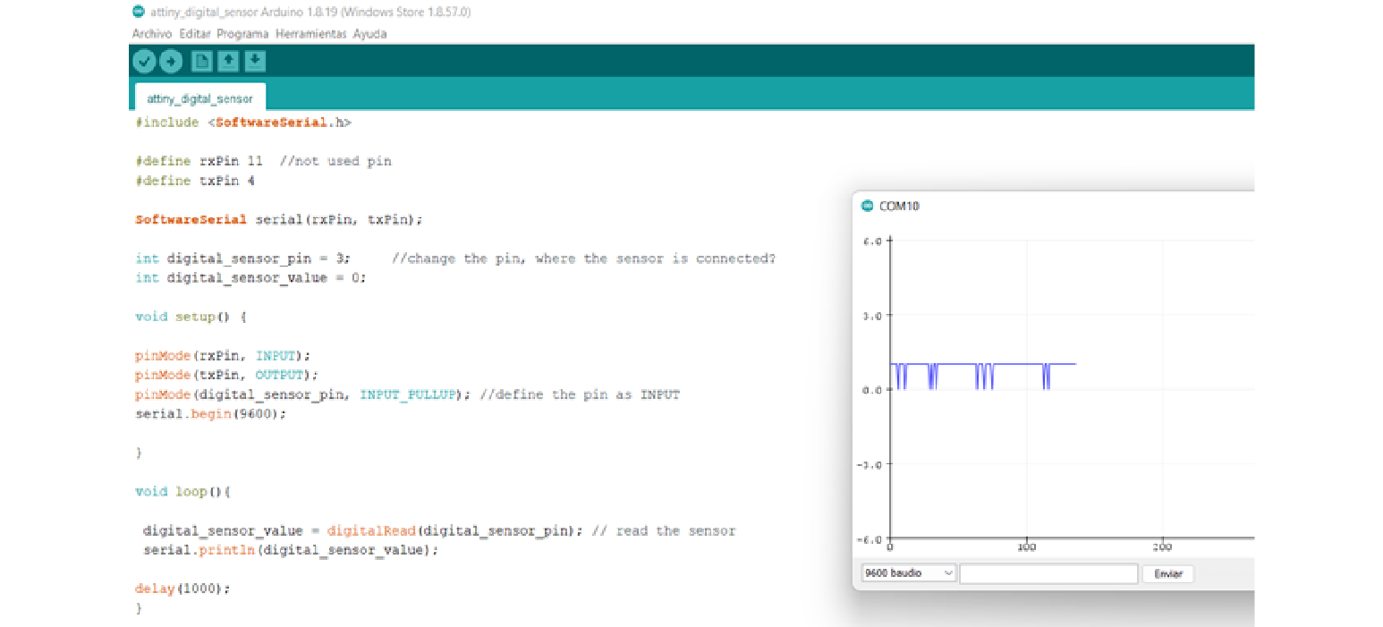
Then, for reading the signal from the ATtiny you need to follow another workflow
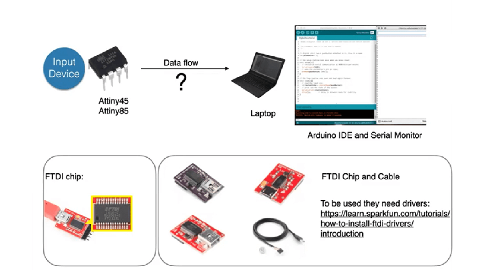
Install drivers for the FTDI chip and prepare the circuit to upload the sketch, then change then circuit with the digital sensor to read the values and show them in the serial monitor/plotter. What I saw in this case was the 1-0 values, if I don’t press it the value in the graphic is 1, but when I press the sensor the value is 0.
▪ Capacitive sensors
During Emmas' lessons I was surprised by the explanation about de body conductivity🤚... Did you know that skin' resistance can be about 100 000 ohms? 😯 More about it ⬇️
Useful readings:
▪ Conduction of Electrical Current to and Through the Human Body
Capacitive sensor + Arduino
Step 1: Prepare Arduino IDE
Install the capacitive sensor library, follow this steps at Arduino IDE:
- Sketch section > Include library > Add libraries
- Select the zip file downloaded
- Check the library is installed by searching it at the Library Manager window
Step 2: Build the circuit
Step 3: Use the following code
The code can be use for one or two conductive sensors, but you can add more if you want. The original codes are in this link. I'm using a 260k ohms resistor this time and as my sensor element I have a copper wire.
#include <CapacitiveSensor.h>

CapacitiveSensor cs_4_2 = CapacitiveSensor (4,2); // 260K resistor between pins 4 & 2
//CapacitiveSensor cs_8_6 = CapacitiveSensor (8,6); // 100K resistor between pins 6 & 8

// cs_4_2 is the name that indicates the pins we're using from arduino
// the creation of the object has two parameters that are the pins used to send out & read the signal

void setup() {
  // put your setup code here, to run once:
    Serial.begin(9600); //open the communication between arduino & computer
}

void loop() {
  // put your main code here, to run repeatedly:
    long total1 = cs_4_2.capacitiveSensor(30); //definition of the variable long total1 that is used to save the reading
    // 30 is the amount of samples that arduino takes to calcule the time to get to a high voltage

     //long total2 = cs_8_6.capacitiveSensor(30);

    Serial.println(total1); //print sensor output 1 on the serial monitor/plotter
    //Serial.println(" ");
    //Serial.println(total2);
    delay(10);
}
Step 4: Try it!
Inmediately when I touch the metal pin out of the copper wire, it reponds and you can see the signal in the serial plotter
This response change dramatically when I DON'T touch the wire, I mean, when I put my fingers close to the wire the signal is not really high, it reaches until 25 approx. So yeah, this sensor is highly sensitive!
▪ Exploring piezoresistive matrix
After that I fully focused on matrix to make kind of a tattoo - touchpad for the skin
Hello again to Kobakant. I chosed to make this matrix that was the easiest one just with copper tape + paper, but there are many others that you can do easily. First I tried it with the Arduino IDE and then I gave a try to the Processing Software
Piezoresistive matrix + Arduino
Step 1: Prepare the matrix and build the circuit
Step 2: Use the following code
//Emma Pareschi- Dec 2020
//Modify example from Pressure Sensor Matrix Code
//parsing through a pressure sensor matrix grid by switching individual
//rows/columns to be HIGH, LOW or INPUT (high impedance) to detect
//location and pressure.
//>> https://www.kobakant.at/DIY/?p=7443

#define numRows 3
#define numCols 3
#define sensorPoints numRows*numCols

int rows[] = {A0, A1, A2};
int cols[] = {5,6,7};
int incomingValues[sensorPoints] = {};

void setup() {
// set all rows and columns to INPUT (high impedance):
for (int i = 0; i < numRows; i++) {
pinMode(rows[i], INPUT_PULLUP);
}
for (int i = 0; i < numCols; i++) {
pinMode(cols[i], INPUT);
}
Serial.begin(9600);
}

void loop() {
for (int colCount = 0; colCount < numCols; colCount++) {
pinMode(cols[colCount], OUTPUT); // set as OUTPUT
digitalWrite(cols[colCount], LOW); // set LOW

for (int rowCount = 0; rowCount < numRows; rowCount++) {
incomingValues[colCount * numRows + rowCount] = analogRead(rows[rowCount]); // read INPUT
}// end rowCount

pinMode(cols[colCount], INPUT); // set back to INPUT!

}// end colCount

// Print the incoming values of the grid:
for (int i = 0; i < sensorPoints; i++) {

  Serial.print(incomingValues[i]);
  if (i < (sensorPoints-1)) {
    Serial.print("\t");}
//    Serial.println("");}
  }


Serial.println();
delay(10);
}
Step 3: Try it!
Issue
I noticed that all the pins in the matrix were not working properly because the values were not changing at the serial monitor. I checked the connections and they were all fine but I used one strip of copper tape over the other and this was causing the issue
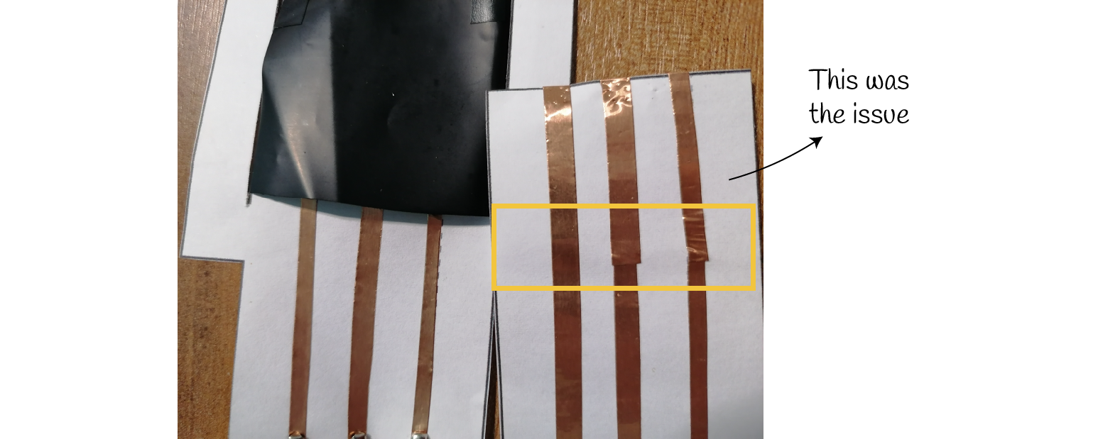
So, I replaced both with using only one long strip and then I tried it again
Fixed
It's working! All the pins are fine now. 📝 Reminder: use only a full copper strip
Piezoresistive matrix + Processing
Step 1: Download and Install the Processing Software
Step 2: Prepare the matrix and build the circuit
Step 3: Use the processing code from Kobakant, it's the same that Emma gave us in the tutorials
Step 4: Try it and explore!
For the serial port number I used at first the number 5 because that was the port from the Arduino IDE, but there was an error so I changed it to 0 and it worked!
String portName = Serial.list()[0]; // set the number of your serial port from 0 to X
Note: you can't use the serial plotter while you are executing the matrix at processing
I made some changes to the code, this is more for visual aspects like changing the colors and shapes. A few tips to personalize your matrix:
By adding the
stroke()andfill()functions before something is drawn, we can set the color of any given shape. There is also the functionbackground(), which sets a background color for the window
size(200, 200);
background(255);    // Setting the background to white
stroke(0);          // Setting the outline (stroke) to black
fill(150);          // Setting the interior of a shape (fill) to grey
rect(50,50,75,100); // Drawing the rectangle
You can draw "primitive" shapes to the screen: rectangles, ellipses, lines, triangles
rect(x,y,w,h);
ellipse(x,y,w,h);
line(x1,y1,x2,y2);
triangle(x1,y1,x2,y2,x3,y3)
For my final code I mostly changed the transparency and the colors. Finally, I played with the position and the size of the rectangles in the rows and columns
| Video | Line code #42 |
|---|---|
 |
rect(rectY+rectSize/4, rectSize * (i%rows)+rectSize/4, rectSize/2, rectSize/2); |
 |
rect(rectY, rectSize * (i%rows), rectSize, rectSize); |
 |
rect(rectY/2+rectSize/2, rectSize * (i%rows), rectSize, rectSize); |
 |
rect(rectY, rectSize * (i%rows)/2+rectSize/2, rectSize, rectSize); |
For the code you use the comand ellipse to change the shape easily
| Video | Code changes |
|---|---|
 |
download code |
Code based on Tom Igoe’s Serial Graphing Sketch
>> http://wiki.processing.org/w/Tom_Igoe_Interview

import processing.serial.*;

String myString = null;
String inString = null;
int lf = 10;    // Linefeed in ASCII

Serial myPort; // The serial port
int rows = 3;
int cols = 3;
int maxNumberOfSensors = rows*cols;
float[] sensorValue = new float[maxNumberOfSensors]; // global variable for storing mapped sensor values
float[] previousValue = new float[maxNumberOfSensors]; // array of previous values
int rectSize = 0;
int rectY;
void setup () {
size(800, 800); // set up the window to whatever size you want
rectSize = width/rows;

//println(Serial.list()); // List all the available serial ports
String portName = Serial.list()[0]; // set the number of your serial port!
myPort = new Serial(this, portName, 9600);
myPort.clear();
myPort.bufferUntil('\n'); // don’t generate a serialEvent() until you get a newline (\n) byte
background(255); // set inital background
smooth(); // turn on antialiasing
rectMode(CORNER);
}

void draw () {
background(255,200,200);
for (int i = 0; i < maxNumberOfSensors; i++) {
stroke(255); //stroke white for the circles
fill(212,sensorValue[i],2421,127);
//rect(rectY+rectSize/4, rectSize * (i%rows)+rectSize/4, rectSize/2, rectSize/2);
//rect(rectY, rectSize * (i%rows), rectSize, rectSize);
//rect(rectY/2+rectSize/2, rectSize * (i%rows), rectSize, rectSize);
rect(rectY, rectSize * (i%rows)/2+rectSize/2, rectSize, rectSize);
if((i+1) % rows == 0) rectY += rectSize;
}
rectY=0;
}

void serialEvent (Serial myPort) {
inString = myPort.readStringUntil(lf); // get the ASCII string
println("test");
if (inString != null) { // if it’s not empty
inString = trim(inString); // trim off any whitespace
int incomingValues[] = int(split(inString, "\t")); // convert to an array of ints

if (incomingValues.length <= maxNumberOfSensors && incomingValues.length > 0) {
for (int i = 0; i < incomingValues.length; i++) {
// map the incoming values (0 to 1023) to an appropriate gray-scale range (0-255):
sensorValue[i] = map(incomingValues[i], 0, 450, 0, 255); // stretch 5×5
sensorValue[i] = constrain(incomingValues[i], 0, 255); // stretch 5×5
println(sensorValue[i]); // print value to see
}
}
}
}
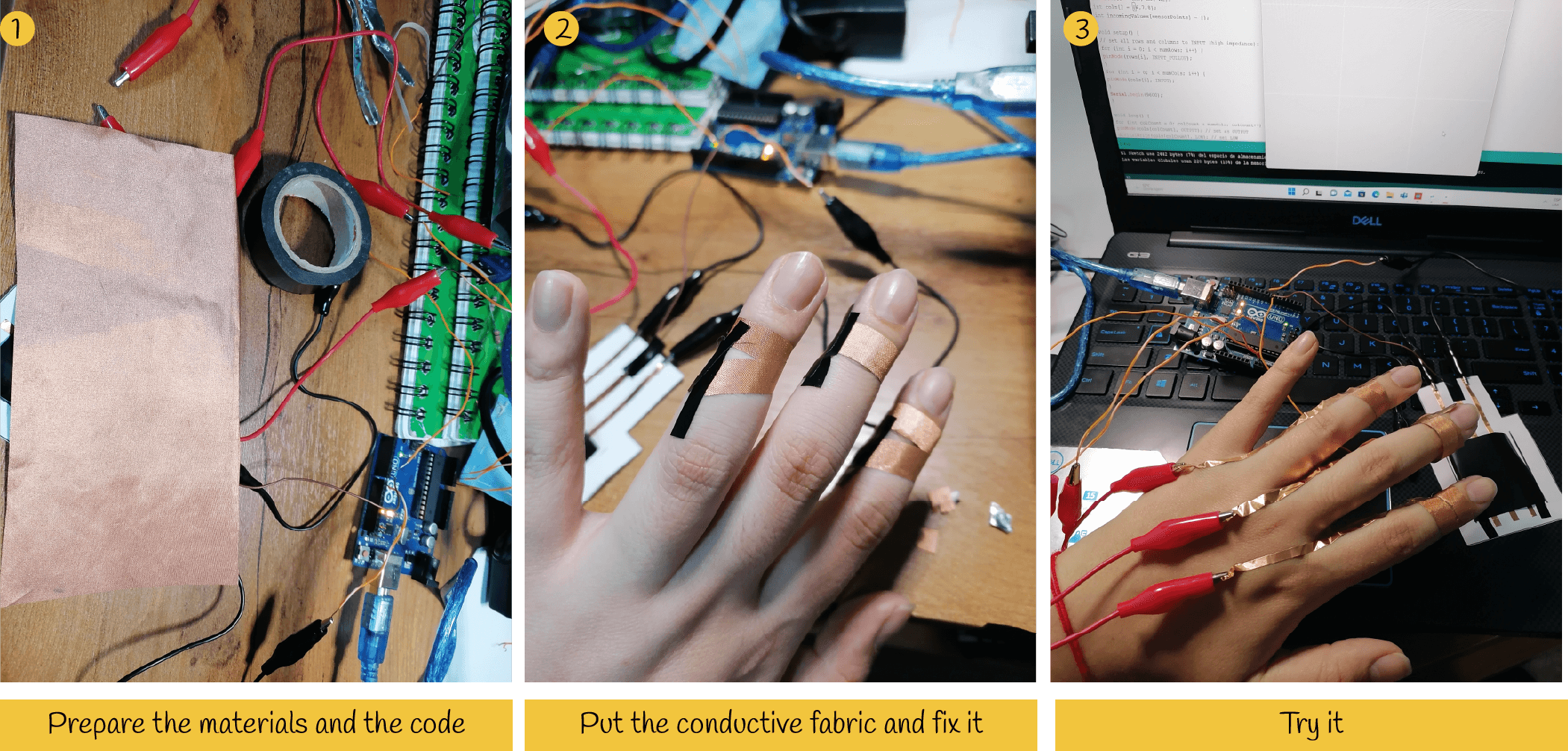
Fingers Touchpad
I was looking to recreate the matrix in my arm using a silicone or a liquid latex but at the end I didn't make that. I changed for another option that can be funny to play with our the fingers.
▪ the previous circuit with the matrix code
▪ conductive textile and velostat
▪ copper tape or aluminium foil
▪ arduino UNO + copper wires + alligator clips
- Place the conductive fabric around the finger, like a ring and fix it with copper tape, the tape should reach up to the back of the hand to be able to connect it to the arduino
- On the fingertips attach velostat and on top of it place another piece of copper tape
- On the other hand repeat step 1
- Connect everything to the arduino and to the computer
- Test and play with your fingers!
| Try 01 | Try 02 |
|---|---|
 |
 |
| I tried with one hand and using the matrix over the paper | I tried with both hands, playing with the fingers |
Useful links:
▪ piezoresistive matrix tutorial - Kobakant - matrix
▪ Glove prototype
Betiana suggested to pass this idea to a glove (or pair of gloves), I was interested in that and made the first prototype of it! I used an elastic fabric for the glove and I sewed the conductives paths with conductive thread. For the fingers I used copper fabric (be careful while sewing it because it can break easily) and also I placed little pieces of the conductive fabric near the wrist, this was helpful to then make the conections to the arduino board.
First I sewed the larger pieces of the finger, then with the same thread I followed a path until the wrist were the other fabric was placed. Then, repeat the same for all the fingers.
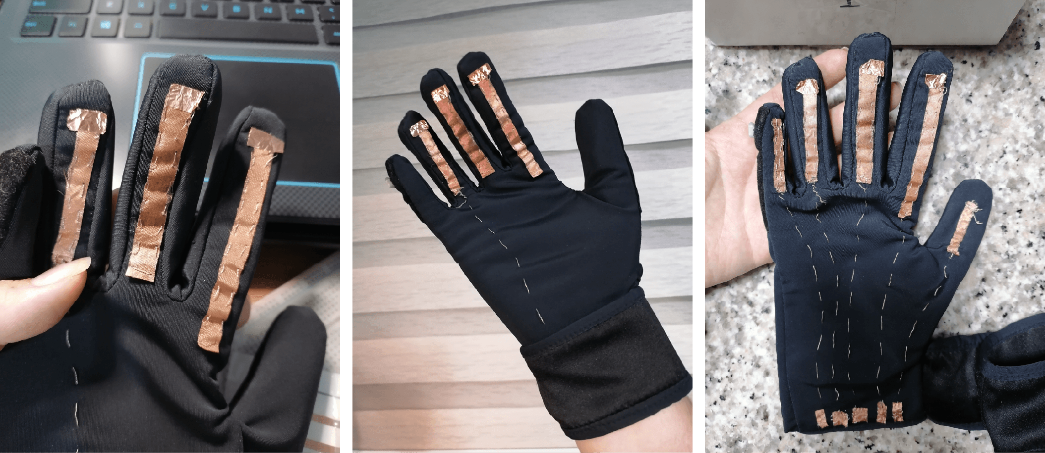
In the video I'm showing the glove only with three fingers because I needed more wires and alligator clips in that moment, but all fingers were working properly (so nice!). Also in the serial monitor at the Arduino IDE all the rows appeared.
The next steps: I know this assignment is more related to skin but I'm indecisive about the other glove, I think this could be so nice to use with a mat, like a kid mat. This could be a great interactive product for children. Now that this glove is working I can think about the possibilities of the other part of the matrix, instead of the piece of paper I showed at the video
▪ Week's outcomes and learning 📌
What a week! I was surprised by all the things I tried, I really learned a lot and enjoyed this week. It was really interesting in all aspects, and I'm curious about the fashion applications of this. I want to try the same matrix usign the attiny, will I make it? I think that will be a great challenge now!