5. E-textiles
- Build at least one digital and one analogue soft sensors, using different materials and techniques.
- Document the sensor project as well as the readings got using the AnalogRead of Arduino
- Integrate the two soft sensors into one or two textile swatches using hard soft connections
- Document the circuit and its schematic
- Document your swatches
- Upload a small video of the swatches functioning
- EXTRA POINT Integrate the swatch into a project
Research
I am fond of the cosmic aesthetic of the e-textile garment Aura Inside by Clara Daguin. I would love to use e-textile for a musical project, like the embroidered synth of Afroditi Psarra or a sound wall in the spirit of Vogel's sculptures.

Aura Inside, 2018 by Clara Daguin.

LED dress, 2007 by Hussein Chalayan.
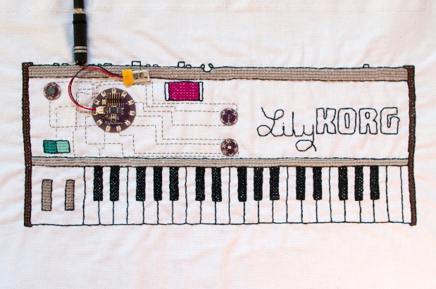
Lilytronica, 2012 by Afroditi Psarra
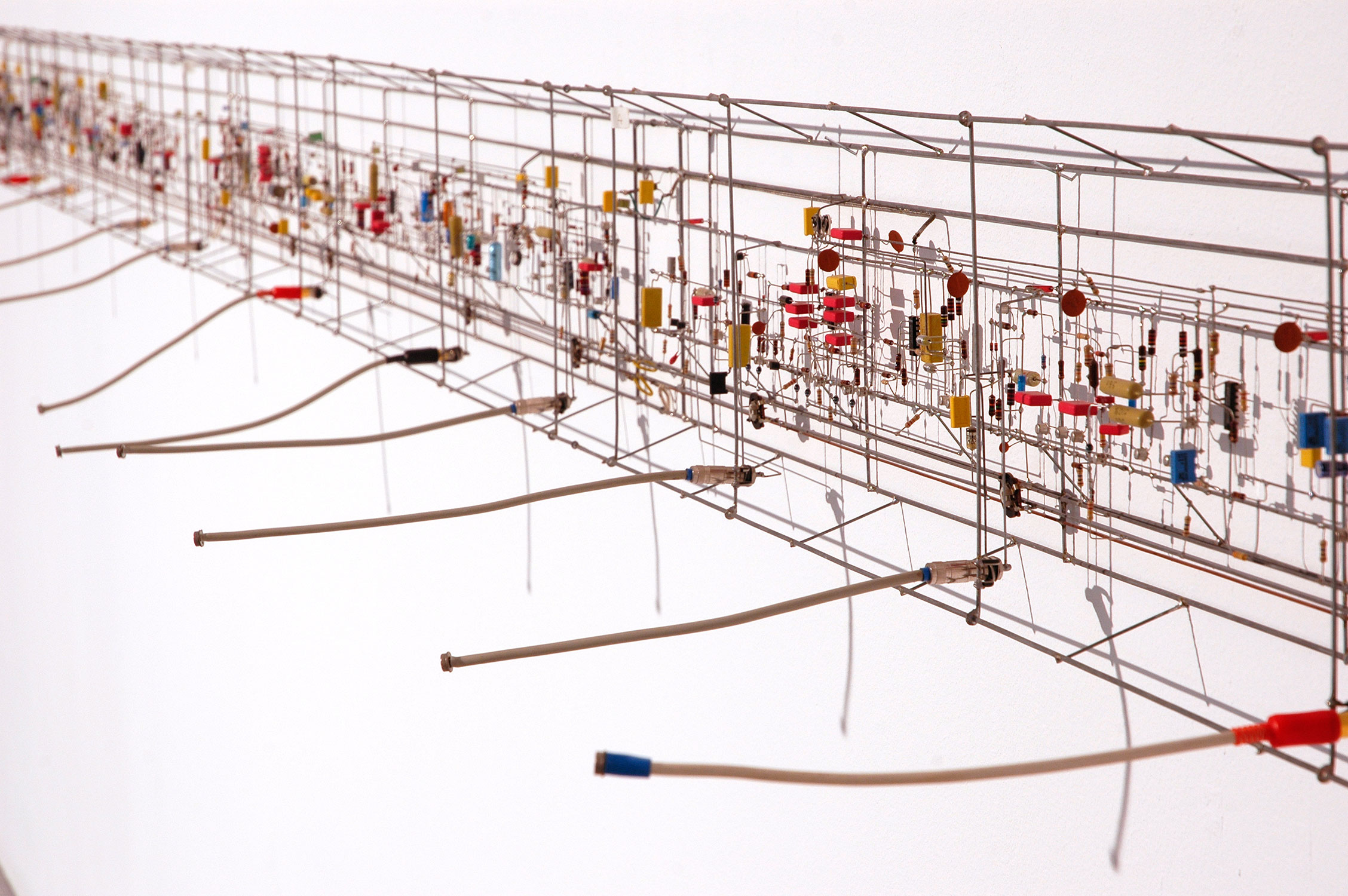
Klangwand, 1991 by Peter Vogel
Shadow Orchestra, 1989 by Peter Vogel
Musical embroidery
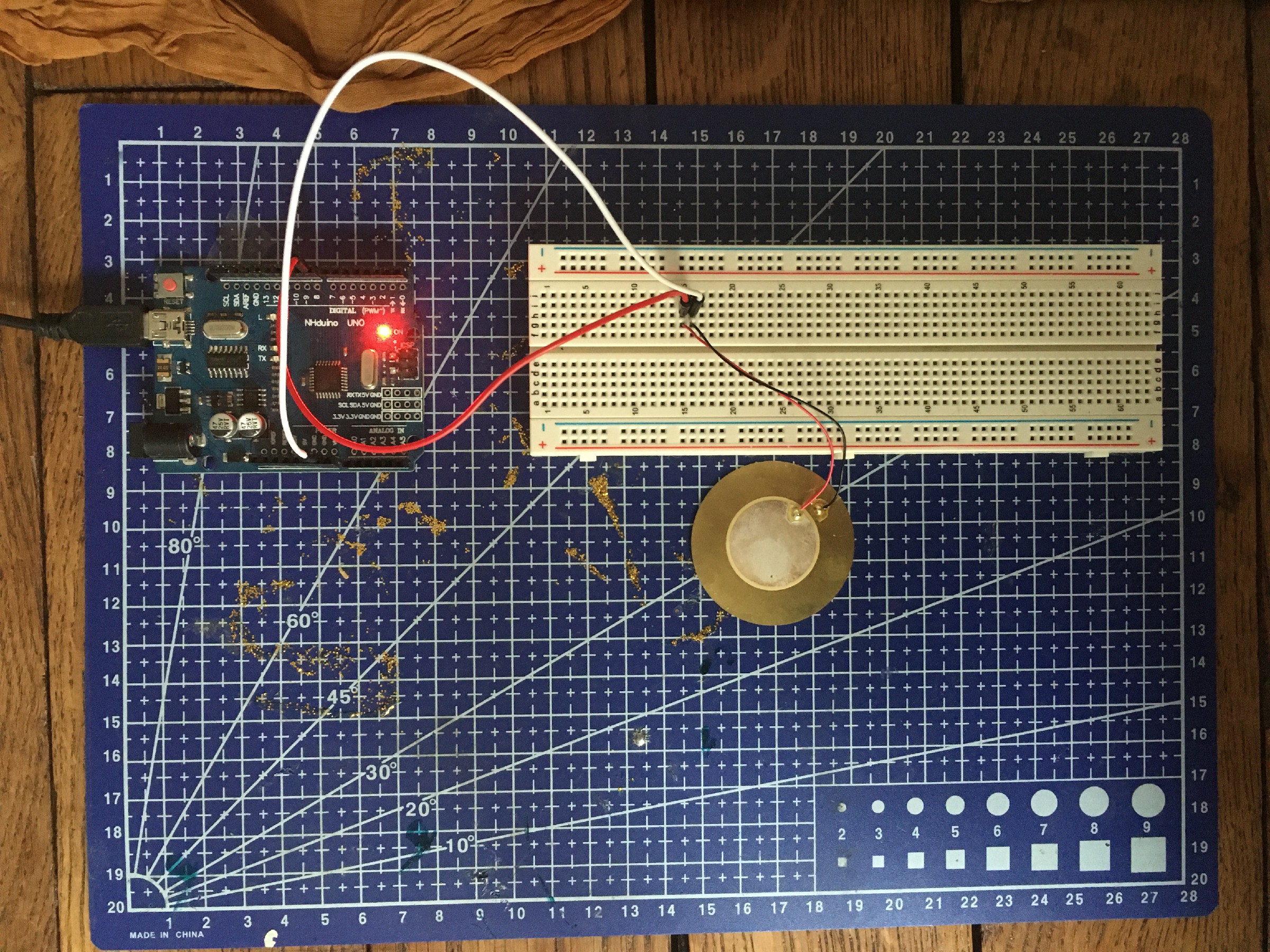
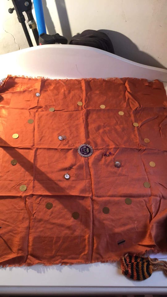
My idea is to use piezoelectric disk in e-textile so as to create a musical embroidery. On a long term goal, I would like to create a musical tapestry, a sound wall made of fabric that reacts to the gesture of individuals. I will use piezo disk both as input (from user) and output (sound).
First I did a first circuit with piezo disk (used as output only) on a breadboard :
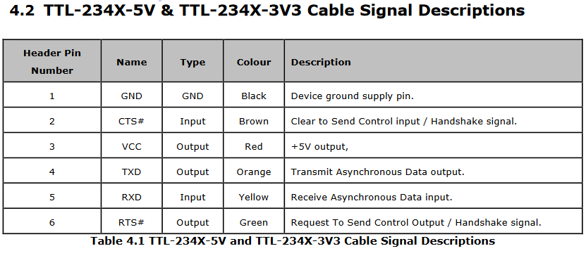
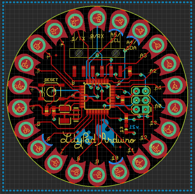
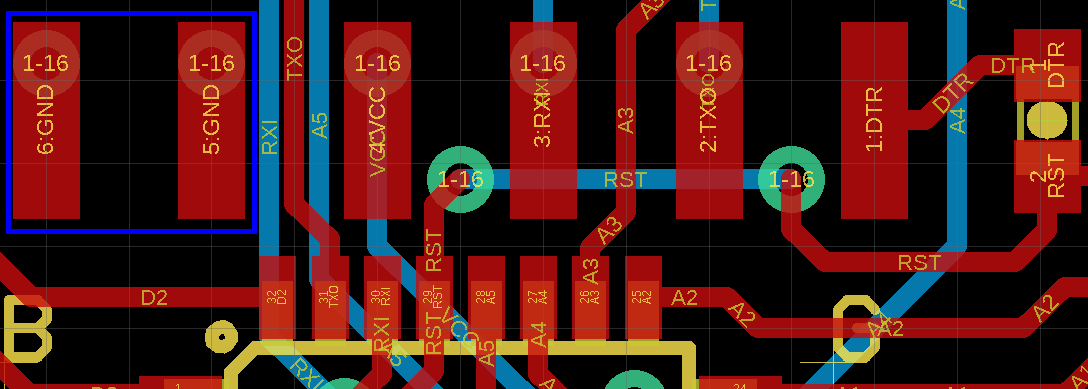
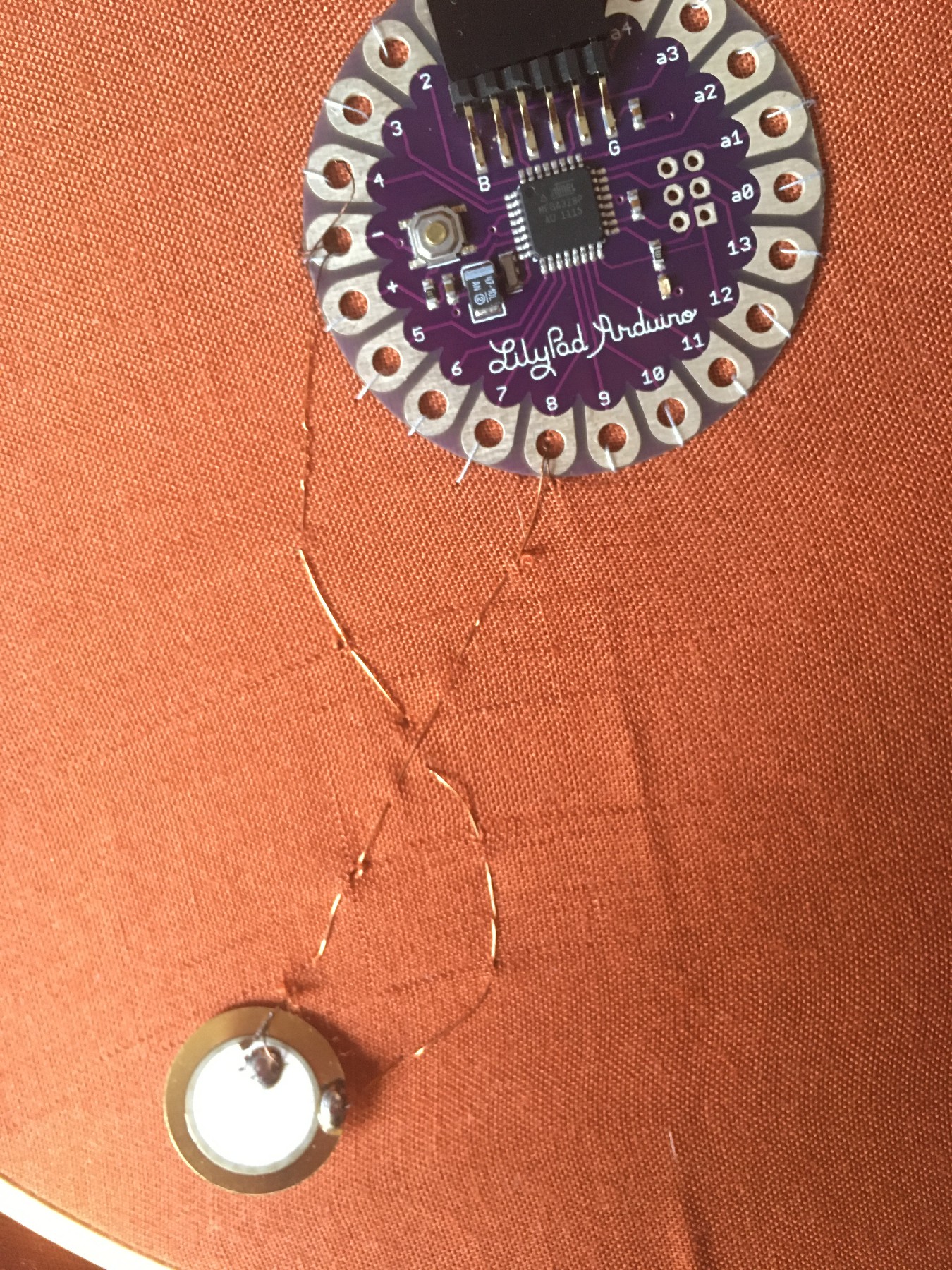
Then I made this circuit on fabric using a Lilypad instead of the Arduino Uno. To program the Lilypad, I connect the board to my computer with a FTDI cable (TTL234X). In order to check the correct wiring with the Lilypad, I checked the documentation of the board and the FTDI cable, specially to see which pin was GND.
I didn't have stainless steel thread so I used a very thin copper thread instead.
Solder piezo disk with copper thread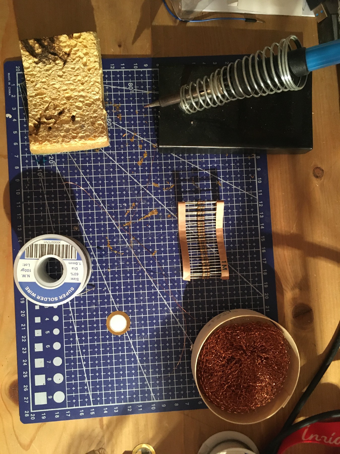
|
Sew the piezo disk and the Lilypad board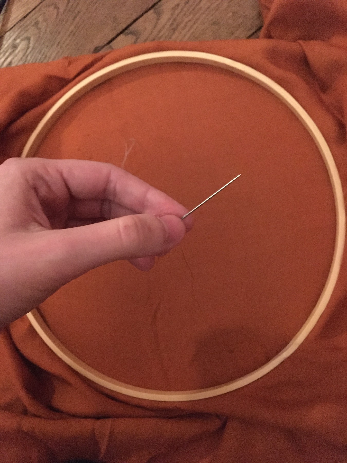
|
|
Now let's play some music !
Below is the code to make the Star Wars tone. The code for the melody was found in this tutorial.
const int c = 261;
const int d = 294;
const int e = 329;
const int f = 349;
const int g = 391;
const int gS = 415;
const int a = 440;
const int aS = 455;
const int b = 466;
const int cH = 523;
const int cSH = 554;
const int dH = 587;
const int dSH = 622;
const int eH = 659;
const int fH = 698;
const int fSH = 740;
const int gH = 784;
const int gSH = 830;
const int aH = 880;

const int audioPin = 9;
const int ledPin1 = 12;
const int ledPin2 = 13;

int counter = 0;

void setup()
{
  //Setup pin modes
  pinMode(audioPin, OUTPUT);
  pinMode(ledPin1, OUTPUT);
  pinMode(ledPin2, OUTPUT);
}

void loop()
{

  //Play first section
  firstSection();

  //Play second section
  secondSection();

  //Variant 1
  noise(f, 250);
  noise(gS, 500);
  noise(f, 350);
  noise(a, 125);
  noise(cH, 500);
  noise(a, 375);
  noise(cH, 125);
  noise(eH, 650);

  delay(500);

  //Repeat second section
  secondSection();

  //Variant 2
  noise(f, 250);
  noise(gS, 500);
  noise(f, 375);
  noise(cH, 125);
  noise(a, 500);
  noise(f, 375);
  noise(cH, 125);
  noise(a, 650);

  delay(650);
}

void noise(int note, int duration)
{
  //Play tone on audioPin
  tone(audioPin, note, duration);
  //tone(A0, note, duration);
  //tone(A1, note, duration);

  //Play different LED depending on value of 'counter'
  if(counter % 2 == 0)
  {
    digitalWrite(ledPin1, HIGH);
    delay(duration);
    digitalWrite(ledPin1, LOW);
  }else
  {
    digitalWrite(ledPin2, HIGH);
    delay(duration);
    digitalWrite(ledPin2, LOW);
  }

  //Stop tone on audioPin
  noTone(audioPin);

  delay(50);

  //Increment counter
  counter++;
}

void firstSection()
{
  noise(a, 500);
  noise(a, 500);
  noise(a, 500);
  noise(f, 350);
  noise(cH, 150);
  noise(a, 500);
  noise(f, 350);
  noise(cH, 150);
  noise(a, 650);

  delay(500);

  noise(eH, 500);
  noise(eH, 500);
  noise(eH, 500);
  noise(fH, 350);
  noise(cH, 150);
  noise(gS, 500);
  noise(f, 350);
  noise(cH, 150);
  noise(a, 650);

  delay(500);
}

void secondSection()
{
  noise(aH, 500);
  noise(a, 300);
  noise(a, 150);
  noise(aH, 500);
  noise(gSH, 325);
  noise(gH, 175);
  noise(fSH, 125);
  noise(fH, 125);
  noise(fSH, 250);

  delay(325);

  noise(aS, 250);
  noise(dSH, 500);
  noise(dH, 325);
  noise(cSH, 175);
  noise(cH, 125);
  noise(b, 125);
  noise(cH, 250);

  delay(350);
}
Afterwards, I will use the piezo both as input and output. Namely, if a user press / knock on the piezo, it will make a bip sound. To do so I define the pin of the piezo disk at the beginning as a INPUT. Then, if the value reach a given threshold, I switch the pin to become an OUTPUT and play a tone. After a few seconds, I stop the tone and switch the pin back to INPUT.
Here is the code to deal with two piezo playing music independently when touched :
const int piezo1=A0;
const int piezo2=A1;
const int ledPin= 13;
const int threshold= 100;

void setup()
{
  pinMode(ledPin, OUTPUT);
  pinMode(piezo1, INPUT);
  pinMode(piezo2, INPUT);

}

void loop()
{
  int val= analogRead(piezo2);
  if (val >= threshold)
  {
    digitalWrite(ledPin, HIGH);
    pinMode(piezo2, OUTPUT);
    tone(piezo2, 500, 200);
    delay(300);
    digitalWrite(ledPin, LOW);
    noTone(piezo2);
    pinMode(piezo2, INPUT);
  }
  else{
    digitalWrite(ledPin, LOW);
    pinMode(piezo2, INPUT);
  }

  int val2= analogRead(piezo1);
  if (val2 >= threshold)
  {
    digitalWrite(ledPin, HIGH);
    pinMode(piezo1, OUTPUT);
    tone(piezo1, 800, 200);
    delay(300);
    digitalWrite(ledPin, LOW);
    noTone(piezo1);
    pinMode(piezo1, INPUT);
  }
  else{
    digitalWrite(ledPin, LOW);
    pinMode(piezo1, INPUT);
  }
}
I added two more piezo and resistors in the circuit. Here is how is wire the resistors on the e-textile circuit :
With a lighter, remove the insulating resin on the copper thread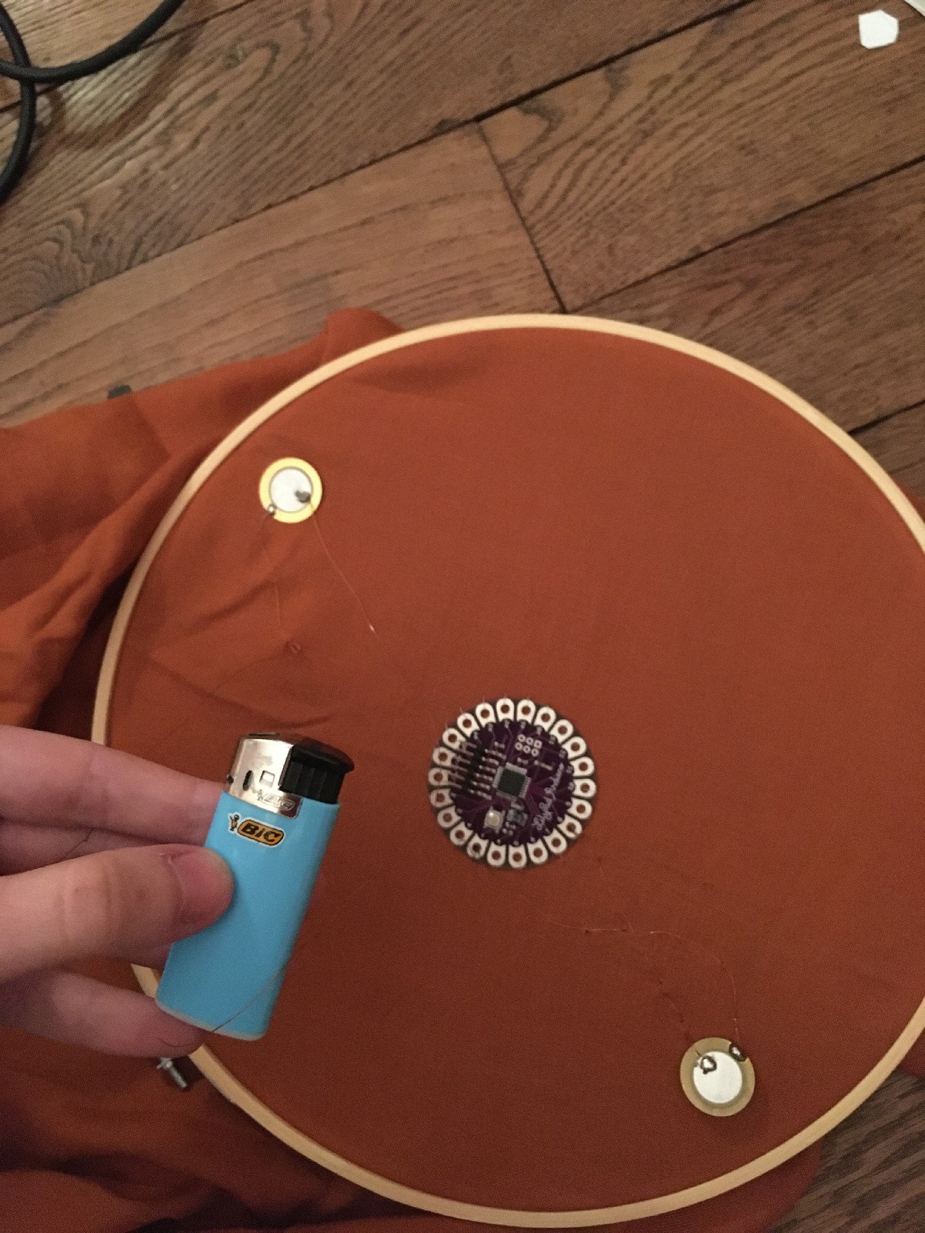
|
Fix the resistor on the fabric and wrap the pin with copper thread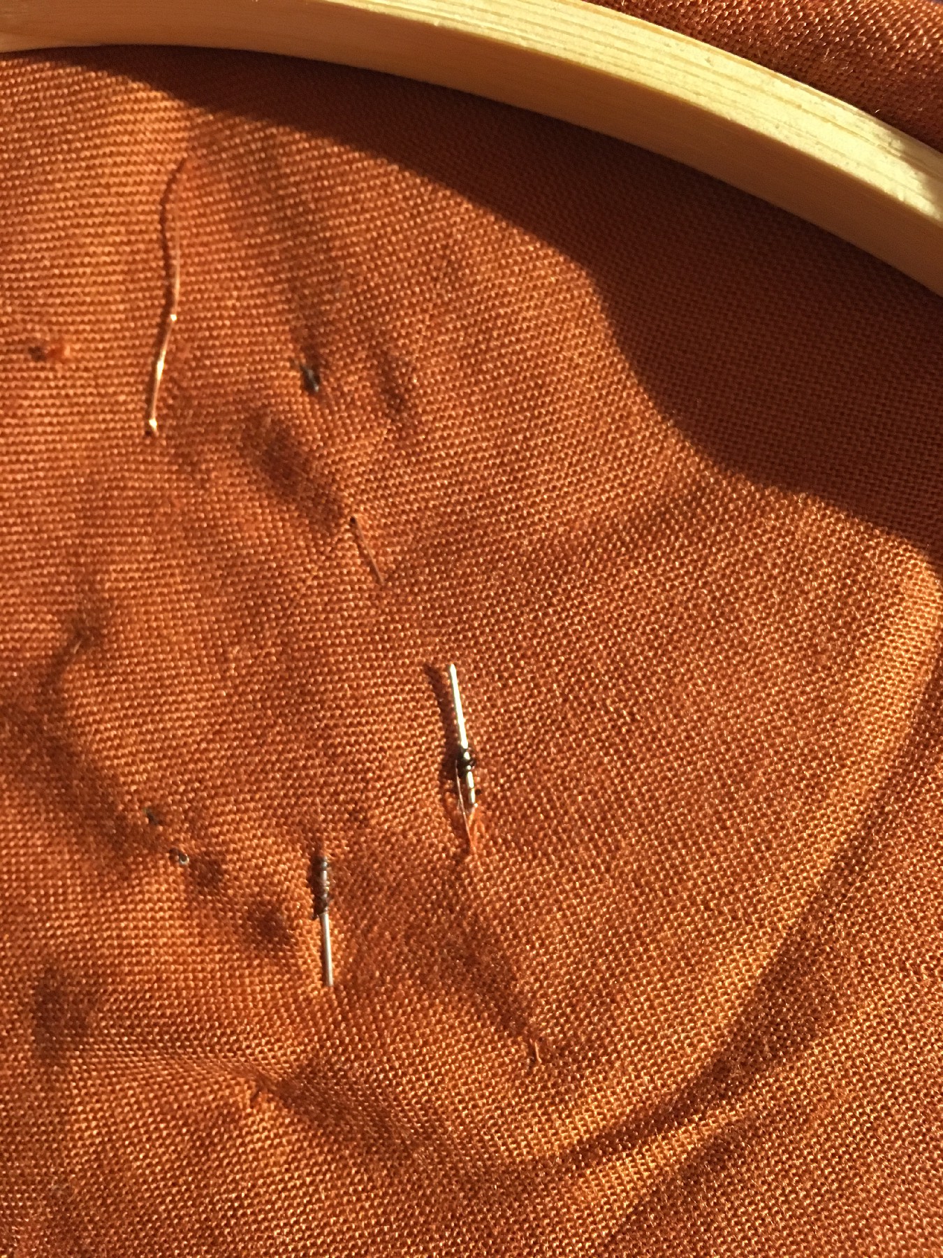
|
Reinforce the wiring with soldering 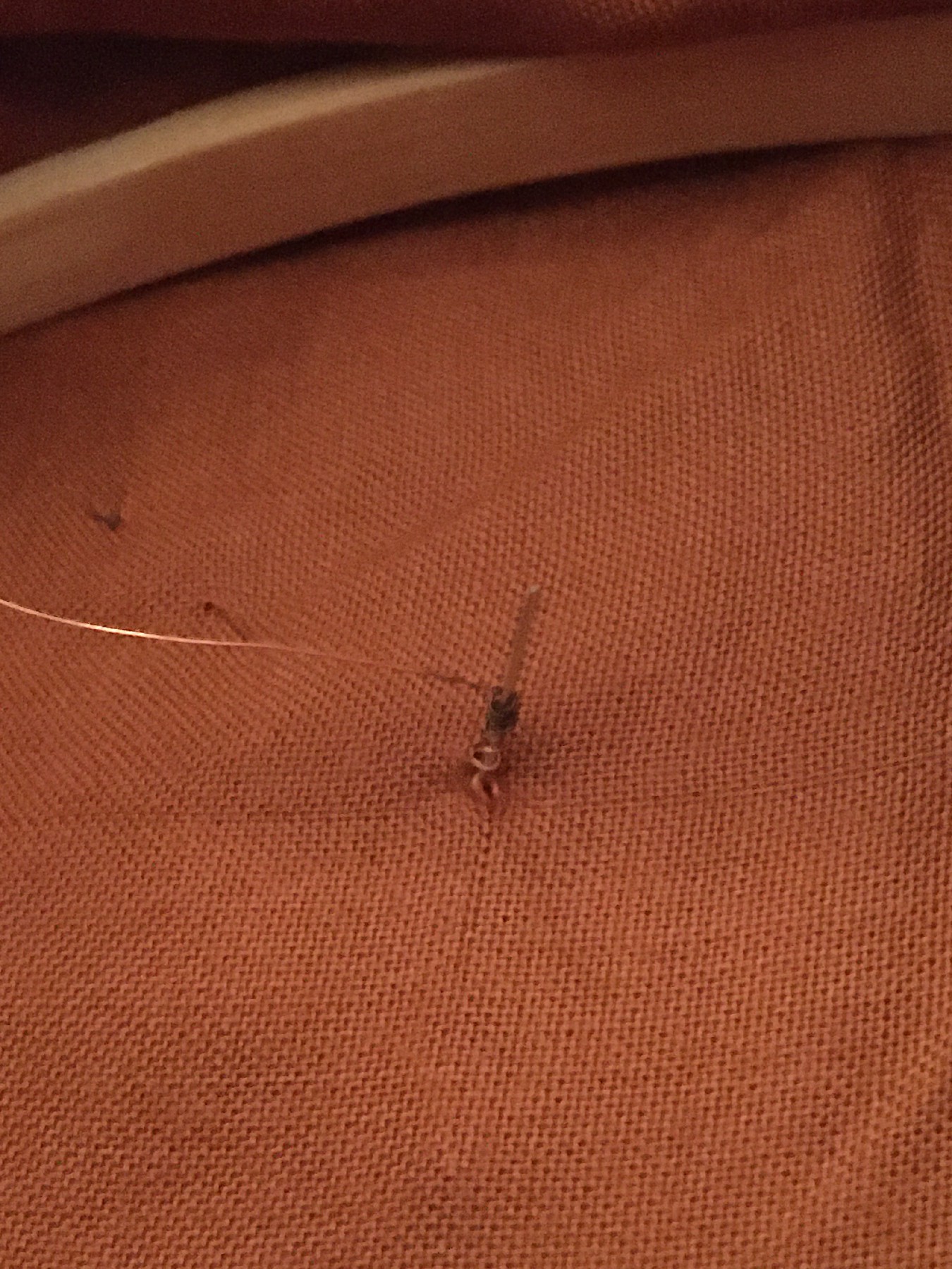
|
It is important to be careful while soldering on fabric, not to put too much soldering otherwise it will burn the fabric.
|
Some things to extend this project : add a lot of piezo disks, add a coin battery for the Lilypad, create different mode of interaction with other sensors (camera, IR, accelerometer?), make a sequencer with the piezo, etc.
Soft pressure sensor
I made a soft pressure sensor using copper tape and piezoresistive material. It consists of three layers placed on the top of each other to make a 6 x 6 pressure matrix :

- Copper columns
- Velostat
- Copper rows
The building process is fairly simple : cut bands of copper tapes. To obtain a square matrix, we should have the same number of lines for rows and columns (in my case 6). Stick the copper tape on the soft material of your choice (plastic, paper, fabric), spaced so that the lines don't touch. Stack the two copper tapes layers with the Velostat layer like a sandwich. I followed this tutorial from Kobakant.
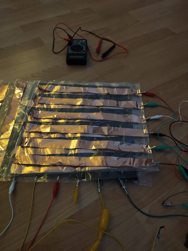
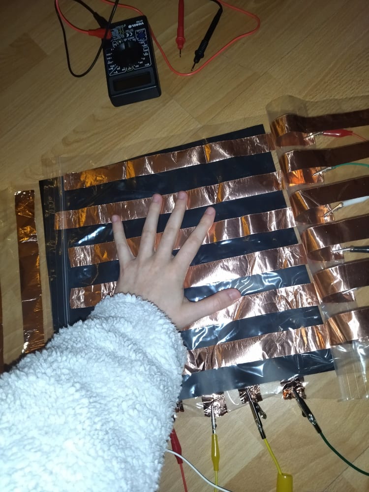
Wire the columns and the rows of the matrix respectively with digital pins and analog pins of the Arduino. I found convenient to use alligator clips to connect the copper tape to the Arduino.

Illustration of the circuit of the pressure sensor matrix, from Kobakant website
Below is the Arduino code to read values from the 6x6 pressure matrix. It goes through the grid by switching individual
rows/columns to be HIGH, LOW or INPUT (high impedance) to detect location and pressure.
In the code, we are printing the values of the matrix to Serial, and formating the value so as the values of the same line are separated by a tabulation (\t) and the rows are separated by a new line (\n). This will be useful when using these data later in Processing.
#define numRows 6
#define numCols 6
#define sensorPoints numRows*numCols

int rows[] = {A0, A1, A2, A3, A4, A5};
int cols[] = {1, 2, 3, 4, 5, 6};
int incomingValues[sensorPoints] = {};

void setup() {
// set all rows and columns to INPUT (high impedance):
for (int i = 0; i < numRows; i++) {
    pinMode(rows[i], INPUT_PULLUP);
  }
  for (int i = 0; i < numCols; i++) {
    pinMode(cols[i], INPUT);
  }
  Serial.begin(9600);
}

void loop() {
for (int colCount = 0; colCount < numCols; colCount++) {
  pinMode(cols[colCount], OUTPUT); // set as OUTPUT
  digitalWrite(cols[colCount], LOW); // set LOW

  for (int rowCount = 0; rowCount < numRows; rowCount++) {
    incomingValues[colCount * numRows + rowCount] = analogRead(rows[rowCount]); // read INPUT
  }// end rowCount

  pinMode(cols[colCount], INPUT); // set back to INPUT!

}// end colCount

// Print the incoming values of the grid:
for (int i = 0; i < sensorPoints; i++) {
  Serial.print(incomingValues[i]);
  if (i < sensorPoints – 1)
    Serial.print("\t");
}
Serial.println();
delay(10);
}
Afterwards, I used the code of the Kobakant tutorial to visualise the pressure with Processing. It used the previous formatting of the data sent via Serial to build a 2D visualisation of the matrix with pressure level in grayscale intensity.
/*
Code based on Tom Igoe’s Serial Graphing Sketch
>> http://wiki.processing.org/w/Tom_Igoe_Interview

Reads X analog inputs and visualizes them by drawing a grid
using grayscale shading of each square to represent sensor value.
>> http://howtogetwhatyouwant.at/
*/
import processing.serial.*;

Serial myPort; // The serial port
int rows = 10;
int cols = 10;
int maxNumberOfSensors = rows*cols;
float[] sensorValue = new float[maxNumberOfSensors]; // global variable for storing mapped sensor values
float[] previousValue = new float[maxNumberOfSensors]; // array of previous values
int rectSize = 0;
int rectY;
void setup () {
  size(600, 600); // set up the window to whatever size you want
  rectSize = width/rows;
  String portName = "COM5"; // set the number of your serial port!
  myPort = new Serial(this, portName, 9600);
  myPort.clear();
  myPort.bufferUntil('\n'); // don’t generate a serialEvent() until you get a newline (\n) byte
  background(255); // set inital background
  smooth(); // turn on antialiasing
  rectMode(CORNER);
}
void draw () {
for (int i = 0; i < maxNumberOfSensors; i++) {
  fill(sensorValue[i]);
  rect(rectSize * (i%rows), rectY, rectSize, rectSize); //top left
  if((i+1) % rows == 0)
    rectY += rectSize;
}
rectY=0;
}
void serialEvent (Serial myPort) {
  String inString = myPort.readStringUntil('\n'); // get the ASCII string
  if (inString != null) { // if it’s not empty
    inString = trim(inString); // trim off any whitespace
    int incomingValues[] = int(split(inString, “\t”)); // convert to an array of ints
    if (incomingValues.length <= maxNumberOfSensors && incomingValues.length > 0) {
      for (int i = 0; i < incomingValues.length; i++) {
      // map the incoming values (0 to 1023) to an appropriate gray-scale range (0-255):
        sensorValue[i] = map(incomingValues[i], 0, 1023, 0, 255); // stretch 5×5
        println(sensorValue[i]); // print value to see
      }
    }
  }
}
The 6x6 matrix has indeed a low resolution, that is why a step further would be to use multiplexer so has to increase the resolution of the matrix.