Prototype 2
Last Update: Apr 6, 2022
January to Apr, 2022
Phase 1: Swimsuit Design
After my midterm presentation, I received a helpful advice about integrating the light placement with the design of the suit. In other words, I aim to make the light placement match the aesthetic and interactive purpose of the suit.
Given this, I made several design considerations based on the following factors:
- using available resources and supplies near me
- keeping budget very low
- using minimal machinery due to limited resources (available machines at home: 3D printer, sewing machine, overlock machine)
Phase 2: Electronics (With Input)
Unlike Prototype 1, this iteration, which is also the final product, uses an accelerometer sensor to control LEDs based on body motion. In this specific case, when the accelerometer is attached to the suit and centered at the chest, two LED strips will light up according to the rotation of the body while swimming. For example, when the body rotates towards the swimmer's right side, the lights on that side of the suit will light - and vice versa.
input image or diagram HERE
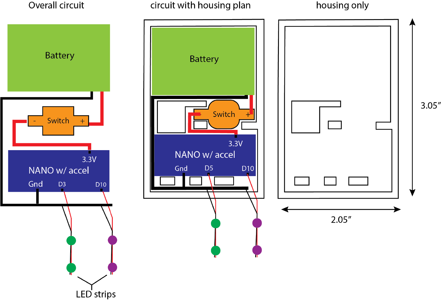
Circuit Design
Similar to Prototype 1, this iteration limits the circuit to 5 components: a 3.7V lipo battery, a button switch, a microcontroller (Arduino Nano 33 BLE Sense with an accelerometer already integrated), and two LED strips.
The first thing I did was prototype the circuit with a tri-color LED pin on a breadboard and USB connection.
Then I tested the circuit wirelessly with a lipo battery, button switch, and 3 separate LEDs.
After testing these prototypes, I created the following schematic for the final circuit with two LED strips instead of three LED colors/pins.
Code
The following is the final code:
/*
  Arduino LSM9DS1 - Simple Accelerometer

  This example reads the acceleration values from the LSM9DS1
  sensor and continuously prints them to the Serial Monitor
  or Serial Plotter.

  The circuit:
  - Arduino Nano 33 BLE Sense

  created 10 Jul 201
  by Riccardo Rizzo

  This example code is in the public domain.
*/

#include <Arduino_LSM9DS1.h>

// initialize axis
float x, y, z;
int degreesX = 0;
int degreesY = 0;

// initialize LED pins to Nano board
int PurpleLED = 10;
int GreenLED = 5;

void setup() {
  Serial.begin(9600);
  //while (!Serial);
  Serial.println("Started");

  pinMode(PurpleLED, OUTPUT);
  pinMode(GreenLED, OUTPUT);
  digitalWrite(PurpleLED, LOW);
  digitalWrite(GreenLED, LOW);

  if (!IMU.begin()) {
    Serial.println("Failed to initialize IMU!");
    while (1);
  }

  Serial.print("Accelerometer sample rate = ");
  Serial.print(IMU.accelerationSampleRate());
  Serial.println(" Hz");
  //Serial.println();
  //Serial.println("Acceleration in G's");
  //Serial.println("X\tY\tZ");
}

void loop() {
  float x, y, z;

  if (IMU.accelerationAvailable()) {
    IMU.readAcceleration(x, y, z);

    //Serial.print(x);
    //Serial.print('\t');
    //Serial.print(y);
    //Serial.print('\t');
    //Serial.println(z);

  }

  // Tilt RIGHT = nanoboard face down, relative to floor
  if(x > 0.3){
    x = 100*x;
    degreesX = map(x, 0, 97, 0, 90);
    Serial.print("Tilting RIGHT ");
    Serial.print(degreesX);
    Serial.println("  degrees");
    digitalWrite(PurpleLED, LOW);
    digitalWrite(GreenLED, HIGH);
  }

  // Tilt LEFT = nanoboard face down, relative to floor
 if(x < -0.3){
    x = 100*x;
    degreesX = map(x, 0, -100, 0, 90);
    Serial.print("Tilting LEFT ");
    Serial.print(degreesX);
    Serial.println("  degrees");
    digitalWrite(PurpleLED, HIGH);
    digitalWrite(GreenLED, LOW);
  }

  // Tilt DOWN = nanoboard vertical, perpendicular to floor
  if(y > 0.8){
    y = 100*y;
    degreesY = map(y, 0, 97, 0, 90);
    Serial.print("Tilting DOWN ");
    Serial.print(degreesY);
    Serial.println("  degrees *CENTER*");
    digitalWrite(PurpleLED, HIGH);
    digitalWrite(GreenLED, HIGH);
  }

  // Tilt UP = nanoboard vertical, slight opposite to tilt down
  if(y < -0.1){
    y = 100*y;
    degreesY = map(y, 0, -100, 0, 90);
    Serial.print("Tilting UP ");
    Serial.print(degreesY);
    Serial.println("  degrees");
    digitalWrite(PurpleLED, LOW);
    digitalWrite(GreenLED, HIGH);
  }

    delay(100);
}
Housing Unit
Using the circuit schematic above, I designed a housing unit in Adobe Illustrator and then imported the .ai file to Rhino. The lines were then extruded into a solid along with an attached base and lid.
The curve lines were then extruded into a solid with a base attached. This solid was then prepared for 3D printing.
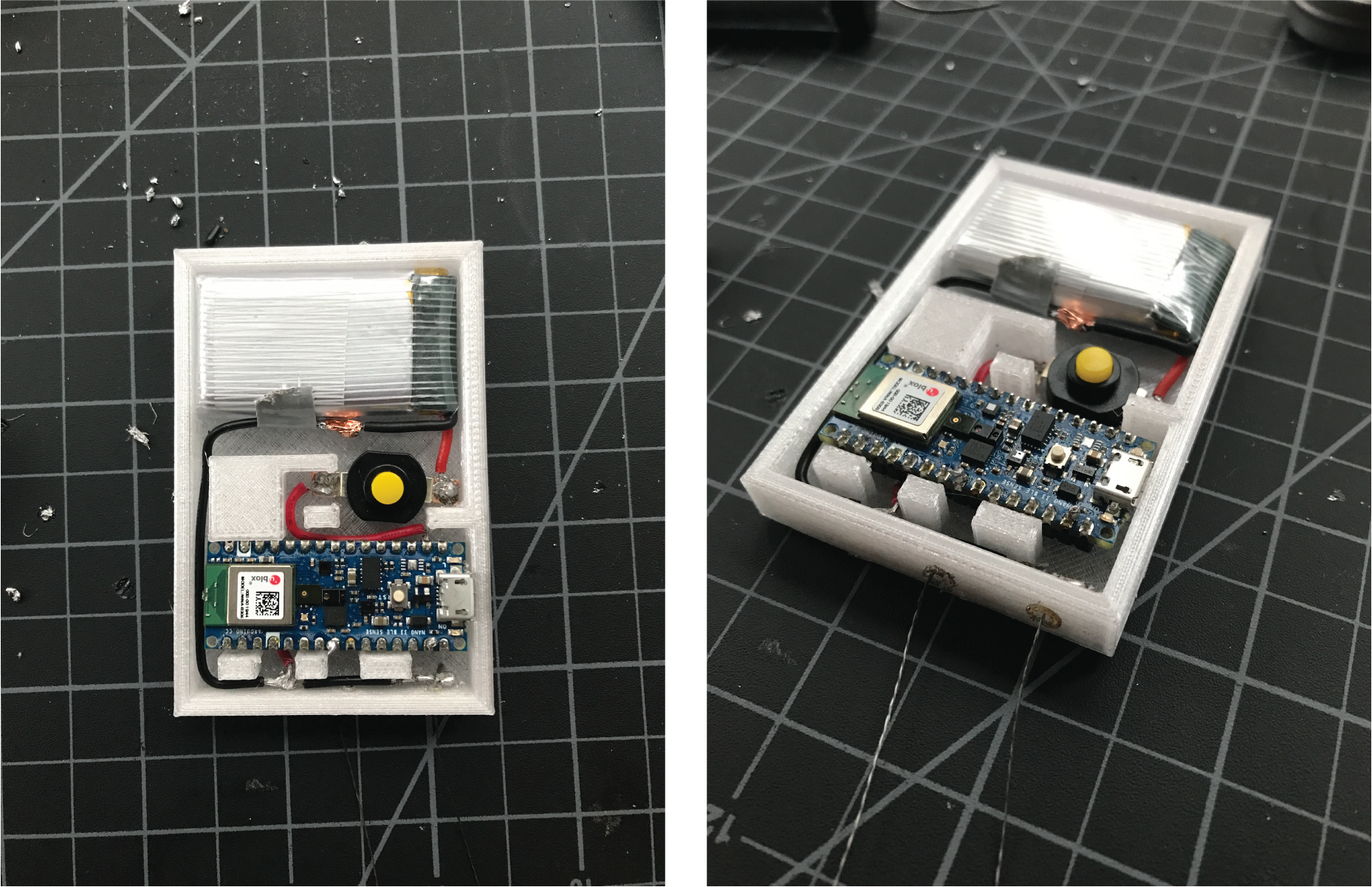
See below for circuit assembly process
Phase 3: Casing + Assembly
Waterproofing Test
To make a quick swatch, I cut some stretchy knit fabric out and zig-zag sewed down the LED strip down. This swatch was then dunked into some water and connected to a battery to test for brightness underwater.
Assembly Process
The Swim Suit
The first part of the assembly process was construction the swimsuit to my size.
Using a previously made pattern, I made some minor adjustments and cut the new pattern out in paper before laying and cutting it out of two kinds of knit fabrics - one for lining and one for the exterior.
-picture-
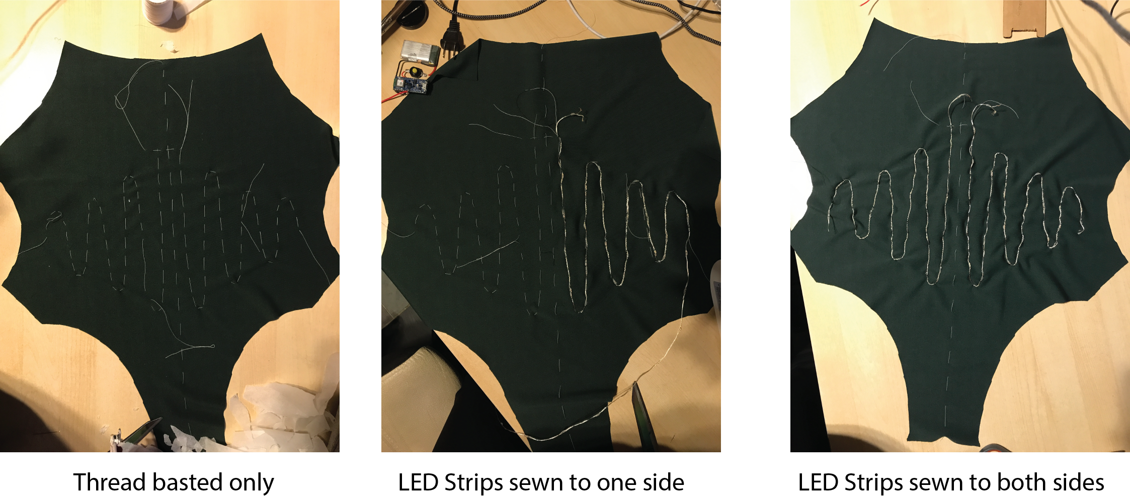
Before sewing the pieces together, I basted the front piece to mark three major features: center front, housing bag placement, and the wave patterns around the belly. These bastings were then used as guidelines to sew the LED strings to the piece.
After this, the remaining pieces of the suit were sewn; the back bottom pieces were sewn together then attached at the side hip with the front
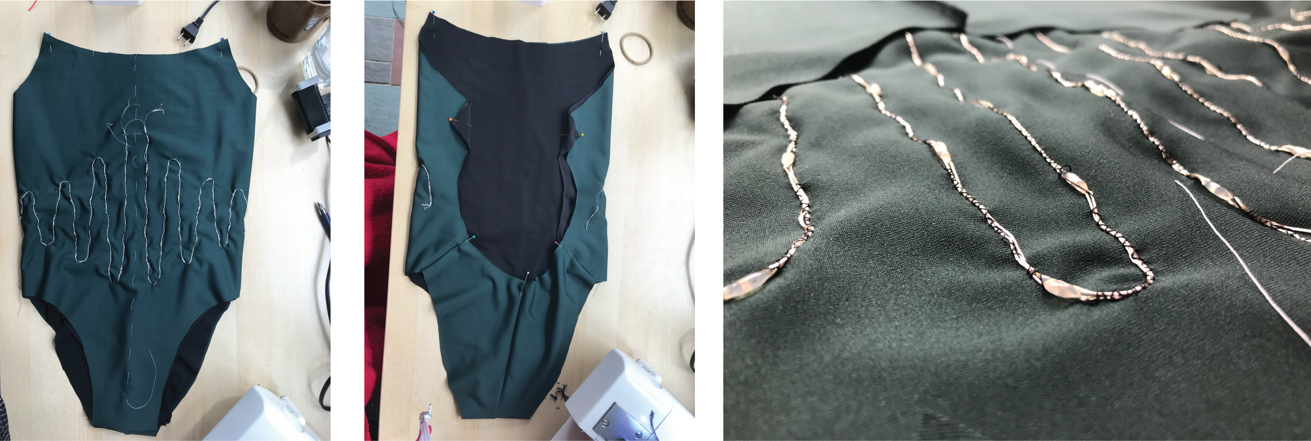
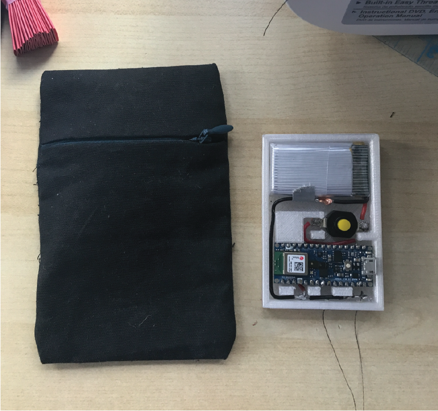
Another major part of the suit that was sewn was the pocket for the circuit housing unit. This was done using an invisible zipper and a 4.25" x 10" rectangle piece of coated canvas.
Finally, I sewed fold-over elastic onto the front side edges to create the straps and back strap.
Circuits Attachment
This is undoubtedly the trickiest part of the project. Connecting the LED strips to the circuit took a great level of patience and time as there were many factors to be considered.
First, I soldered the primary electronic components together: the 3.7V lipo battery, button switch, and the Arduino Nano 33 BLE Sense board. Meanwhile, the housing unit for these parts were 3D printed.
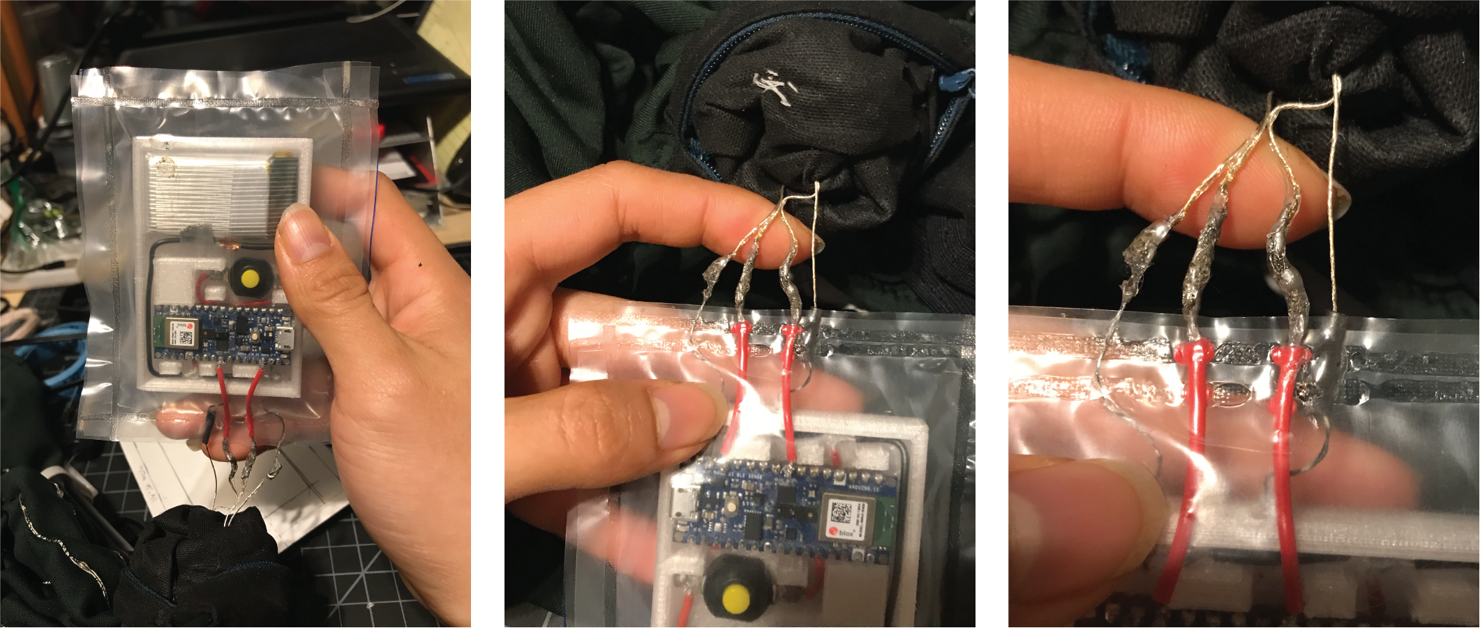
I then used an impulse sealer to close and sandwich the circuit between two layers of plastic. However, the wires needed to connect the LED strips to the circuit were left hanging out. In this specific case, I chose conductive thread to connect the grounds and jumper wires for the positive voltage (??). For insulation of these joints, I used E6000 Craft Glue and tried to cover as much of the wiring as possible. (Note: the unburned parts of the LED strips were already insulated with a special coating so I placed the glue until this point)
Before any interaction with water, I tried on the suit and took footage of its behavior on land:
Phase 4: Swim Test
At Home
No I did not swim at home. However, I did simulate submersion by dunking the circuit portion of the suit into a big bowl of water
At Pool
With the latest prototype, I ran 2 swim tests in total. The first one failed completely but the second one lasted a bit longer.
The good news: the LED strips lit nicely and brightly for longer, and responded to the rotation for a period of time.
The bad news: the led did not respond longer than about 5min to the rotation and not enough footage was captured to show that. In the end, I found out that some areas of the joint connections were exposed because there was not enough craft glue insulating it sad. But the potential to do this again successfully is very bright and I'm excited with having it work at all!
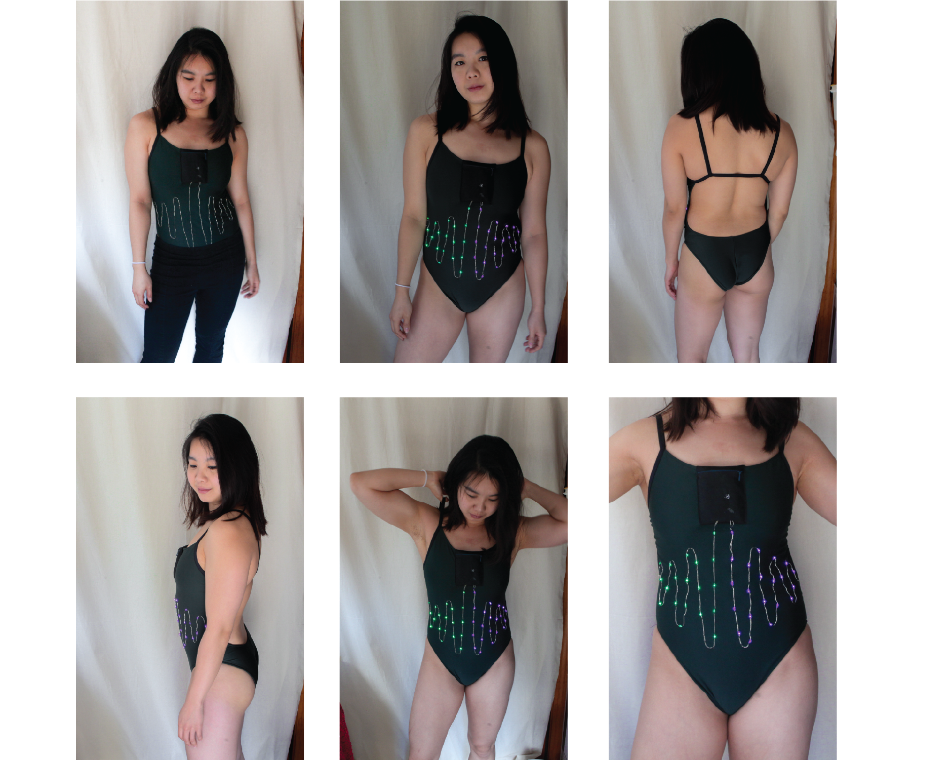
Final Product
After assembly, this is the final product and fit:
Files
Housing unit (.3dm)
Housing unit (.stl)