WEEK 5 - E-TEXTILES

Last Update: Nov 7, 2021
October 18-24, 2021
This week I learned how to integrate soft circuitry into textiles by understanding the basic concepts of electronics and sensors.
Keywords: Arduino, electric circuits, soft materials, conductive thread, alligator clips, wires, batteries, coin batteries, Sparkfun, Adafruit, Kobakant, coding, language, digital sensors, analog sensors, LED, circuitry, velostat, conductive fabric, multimeter, resistors, breadboard
Quick Summary
 Tools/Resources Learned:
- Arduino Version 1.8.10
- Sparkfun
- Adafruit
- Kobakant
 Tools Refined:
- Adobe Illustrator Version 2021 - a photo editing program
- Adobe Lightroom Version 2021 - a photo editing program
- Canva: a graphic designing platform
- DSLR Camera: Canon 5D Mark II*: - the camera I used to take final photos
- Vimeo
 What I still want to learn better:
- How to integrate or use other trim materials as sensors
Obtaining the Materials
This week was a rather expensive one, primarily because of the materials I had to purchase. Here is a list of those materials:
- Adafruit Stainless Conductive Thread
- Adafruit Velostat/Linqstat
- Zehhe Copper Foil Tape
- Adafruit Conductive Knit Jersey
- Multimeter
- Aliigator Clips
- Wiring
- Resistors: 100, 220, 10k Ohm
- LED - color variety pack
- Sparkfun Firefly Jar Starter Kit
- AVR Programmer Kit
Research, Inspiration, and Practice
Needless to say, my first sources of inspiration were lecturers Liza Stark and Emma Pareschi. I am grateful for their guidance and tutorials that helped me start my e-textiles journey this week.
Another source of inspiration was Kobakant which had an incredible library of example projects.

Similarly, Adafruit's example projects also added to my inspiration with what could be done with e-textiles.
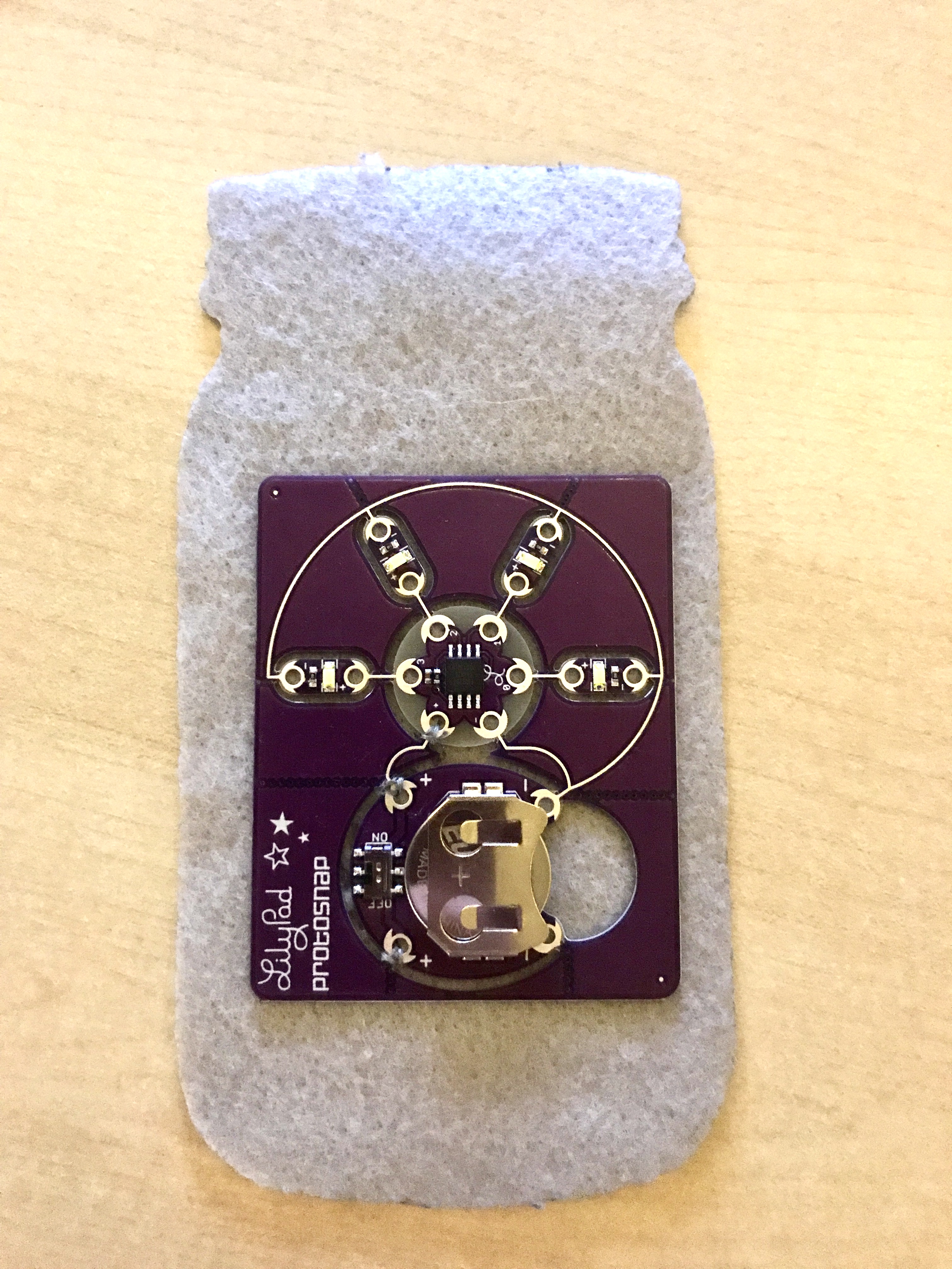
Practicing with Sparkfun
This is my very first time working with conductive thread so to get some extra practice with it, I played with a Sparkfun kit that let me assemble an LED firefly jar. I followed instructions provided by Sparkfun online and used the conductive thread and needle the kit provided to sew down the board onto one side of the felt jar. First I sewed all the positive connections and then all the negative connections.
Here is the final result: TBA
Practicing with Breadboards
I needed a refreseher on how to use breadboards so for a quick review, along with Emma's tutorials, I made a simple circuit with an LED and a 3V coin battery.
Simple circuit with LED:
Next I added a branch/connection to the circuit using conductive thread:
Digital Sensor
Makeshift Button
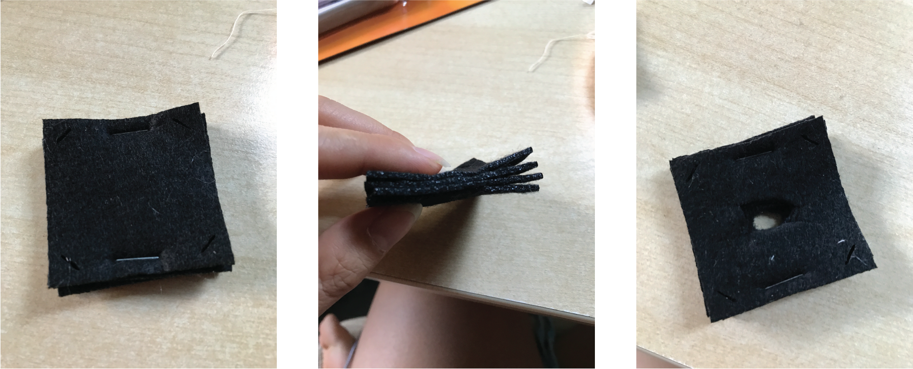
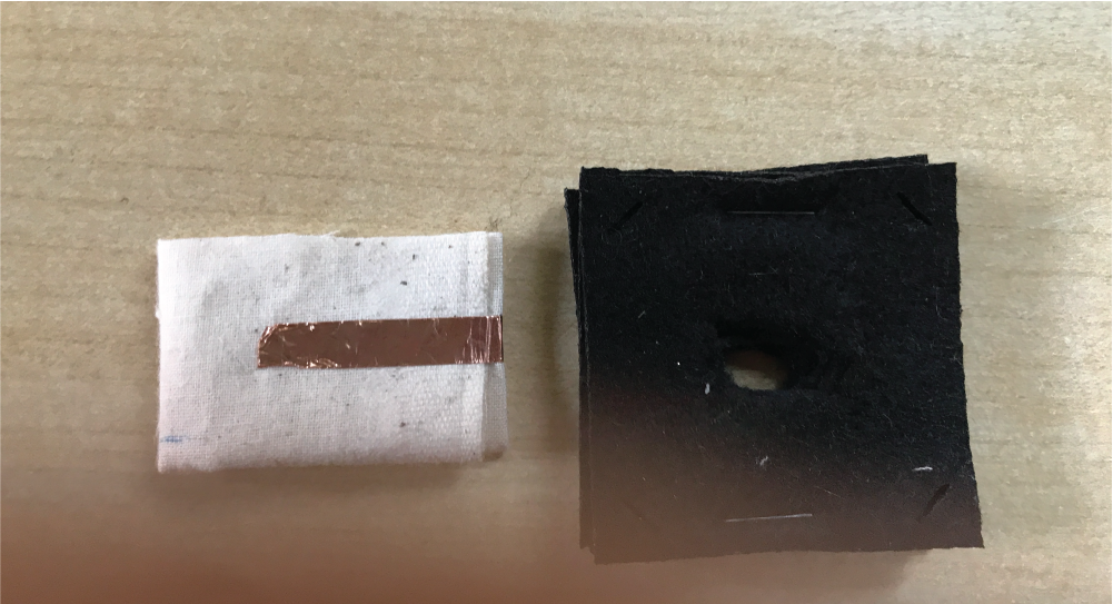
I made a makeshift button for the digital sensor using the felt squares laser cut from week 3. I took 4 pieces and stapled them together on two sides and then cut a hole through the middle.
I then made two pieces of muslin, each folded repeatedly to become 8 layers. I closed the folds with copper tape and used alligator clips to hold down each muslin piece to each side of the felt.
The placement of this sensor went to where my conductive thread was from the second circuit of my breadboard practice (see last section above); it was connected between the power supply (+) and the LED.
Hook and Eye
Instead of the button, I practiced making digital sensors using conductive thread, a hook and an eye.
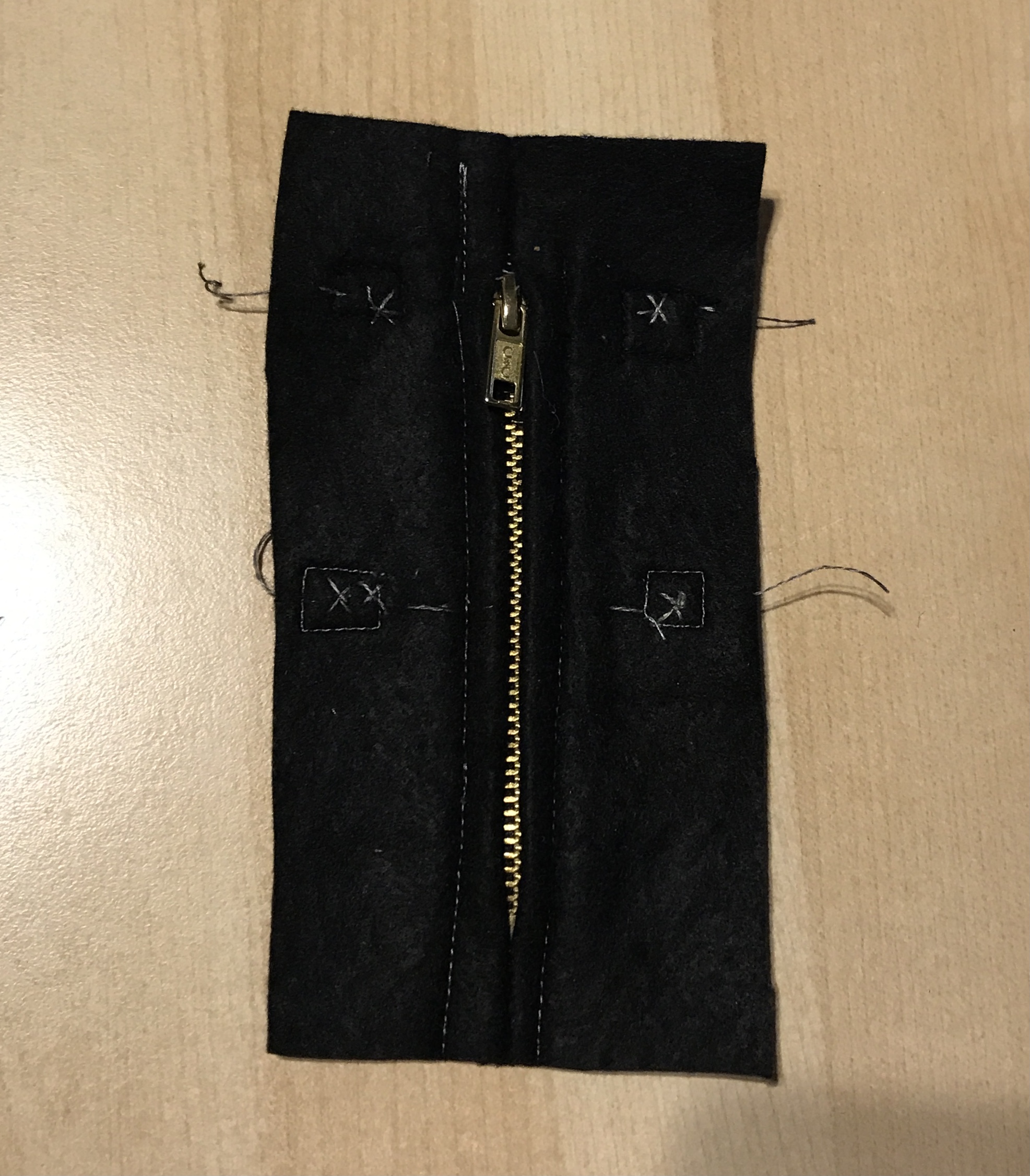
Zipper
My last practice with digital sensors was using conductive thread to connect my 3V coin battery to a metal zipper, which was then connected to an LED before connecting back to the battery.
At this point, I didn't have a metal zipper on its own. Instead, the only metal zipper I had was on my pencil bag so I used that for this practice.
1 LED:
Just for fun, I added a second LED to the circuit (in parallel), so that I could see the effects of closing the zipper and watching the LEDs turn on one by one.
2 LEDs:
Analog Sensor
To make an analog sensor I used the following materials:
- Breadboard
- Wires
- 3V coin battery + holder
- One-sided alligator clips
- Velostat
- Conductive copper fabric
As the following video shows, I cut a piece of the copper square on each side to make sure the alligator clip I was using doesn't touch both pieces of copper squares (or else the circuit would just assume a straight connection). Then I made a velostat sandwich with these copper squares. Once connected with all the other components, I used the blue LED as an indicator of the pressure applied to the velostat from both sides of the copper fabric; the harder I squeezed, the brighter the LED got.
Digital Sensor (Arduino)
To make an analog sensor I used the following materials:
- Breadboard
- Wires
- One-sided alligator clips
- Arduino Uno
- Arduino USB Connector + Adapter for Macbook Pro
- Digital button sensor made earlier
along with the following code through the Arduino IDE:
/*
  Blink

  Turns an LED on for one second, then off for one second, repeatedly.

  Most Arduinos have an on-board LED you can control. On the UNO, MEGA and ZERO
  it is attached to digital pin 13, on MKR1000 on pin 6. LED_BUILTIN is set to
  the correct LED pin independent of which board is used.
  If you want to know what pin the on-board LED is connected to on your Arduino
  model, check the Technical Specs of your board at:
  https://www.arduino.cc/en/Main/Products

  modified 8 May 2014
  by Scott Fitzgerald
  modified 2 Sep 2016
  by Arturo Guadalupi
  modified 8 Sep 2016
  by Colby Newman

  This example code is in the public domain.

  http://www.arduino.cc/en/Tutorial/Blink
*/

int pin_led = 3;
int pin_sensor = 8;

int sensor_value = 0;

// the setup function runs once when you press reset or power the board
void setup() {
  // initialize digital pin LED_BUILTIN as an output.
  pinMode(sensor_value, OUTPUT);
  Serial.begin(9600);
  // initialize digital pin for LED as an output.
  pinMode(pin_led, OUTPUT);
}

// the loop function runs over and over again forever
void loop() {
 // read the state of the pushbutton value:
  sensor_value = digitalRead(pin_sensor);

  // check if the pushbutton is pressed. If it is, the buttonState is HIGH:
  if (sensor_value == HIGH) {
    // turn LED on:
    digitalWrite(pin_led, HIGH);
  } else {
    // turn LED off:
    digitalWrite(pin_led, LOW);
  }
}
This was a simple code I used from the Arduino Sketch Examples called "Button", where the LED in my circuit would stay on until/unless I pressed the button.
Final Swatch (in progress)
Prototyping
Using a breadboard, I made a prototype of the circuit I'll be using in my final swatch that would integrate both a digital sensor and analog sensor.
Using CircuitLab I sketched this circuit in the following schematic:
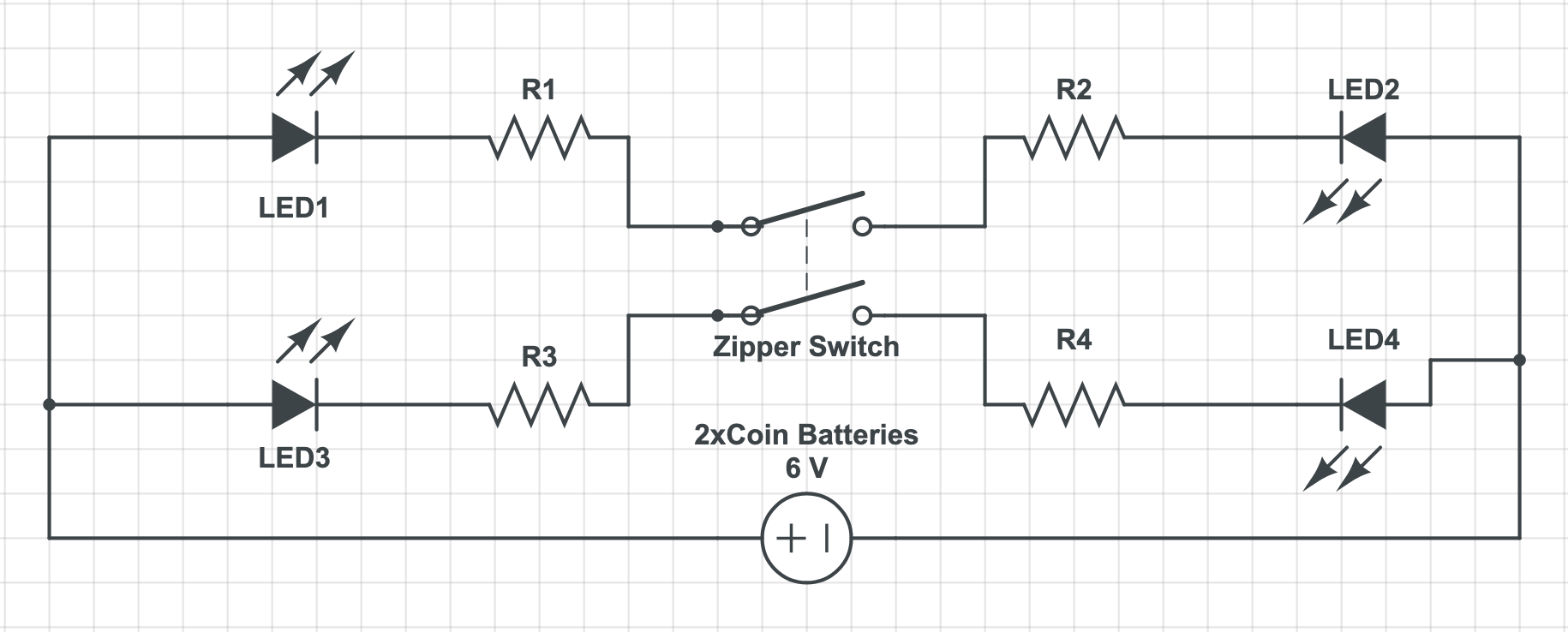
Sewing
In this case, the digital sensor will be a zipper and the analog sensor is a piece velostat sandwiched between a piece of copper fabric and some conductive thread.
Monitoring
I used an Arduino to track the voltage as I press down on the sensors on either side of the zipper switch using the following code (File > Examples > Basics > AnalogReadSerial):
// the setup routine runs once when you press reset:
void setup() {
  // initialize serial communication at 9600 bits per second:
  Serial.begin(9600);
}

// the loop routine runs over and over again forever:
void loop() {
  // read the input on analog pin 0:
  int sensorValue = analogRead(A0);
  // print out the value you read:
  Serial.println(sensorValue);
  delay(500);        // delay in between reads for stability
}
The harder I pressed on the sensors the higher the reading.
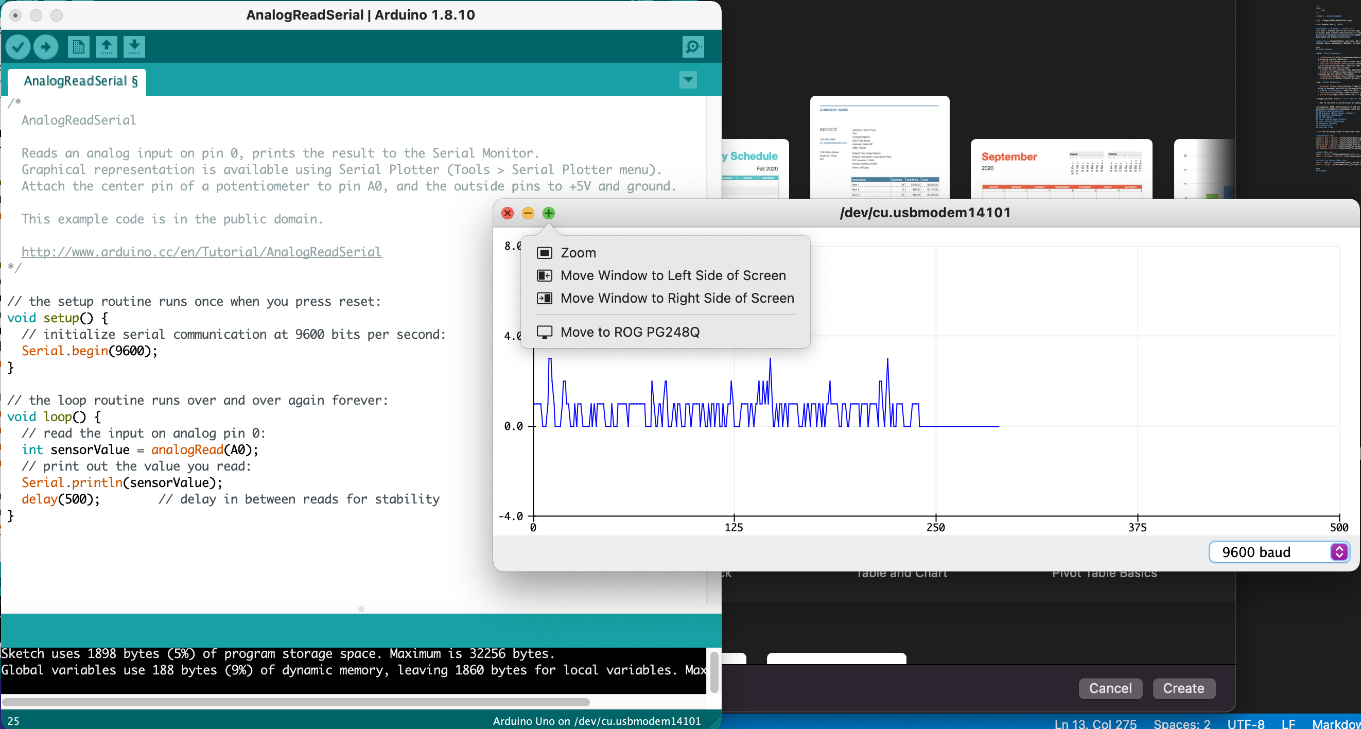
Note: this reading was for one of the two rows of analog sensors.
The following video also shows how the resistance decreases across one of the rows when I press on the analog sensors.
Problem Areas
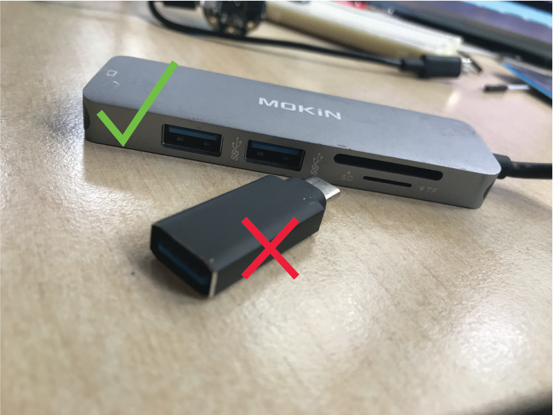
Adafruit Gemma Connection Error
Problem
At some point I wanted to make a swatch that integrated a smaller board than the Arduino and came across the Adafruit Gemma. To set up I followed Arduino's link
Unfortunately, when uploading a Sketch through Arduino IDE, an error continued to pop up.
Error: Could not find USBtiny Device (0x1781/0xc9f)
According to learn.adafruit.com, this error required for the Gemma to have a pulsing red light when connected.
However, no matter how many times I pushed the button or restarted the Gemma, I couldn't get that light.
Solution
First, make sure that the cable being used is a Micro-USB to USB 2.0 cord. Second, since I'm using a Macbook Pro with only 2 Thunderbolt ports, I found that the best adapter was a hub, as opposed to a single/direct adapter for USB to USB-C.
Download Links
Basic Blink (.ino)
Blink with Sensor (.ino)
Final Swatch Analog Read - every 0.5 sec (.ino)
Other Resources
- Kobakant
- Instructables - Conductive Fabric
- Instructables - 2 batteries
- Attaching an LED String to a battery