13. Skin Electronics
Inspirtation
For my future I woudl like to do something in edutainment or costume design. This week got me really excited. As a inspiration for my mask I have created a moodboard of pictures of cyberpunk & afropunk figures with a little bit of alien style.

Process and workflow
Side Project - Melting my Credit Card
List of Tools
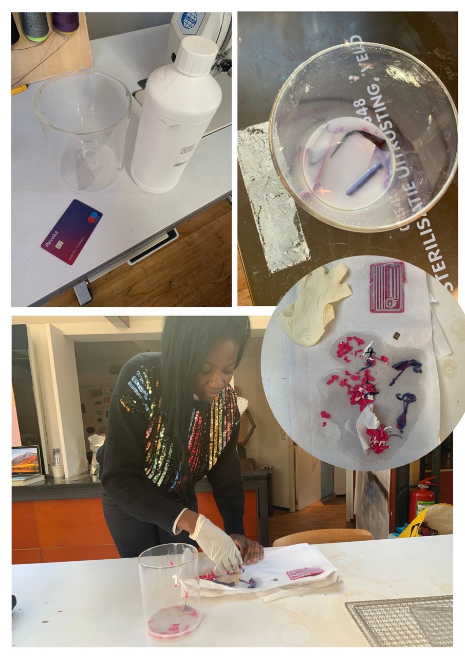
I have wanted to put my credit card chip into 3D printed ring, but I have encountered, that the new creditcards have different wirings and for this reasons it would take a bit longer then a week to finish the project. For the ring to or any sking gadget with a ring, you need your creditcard chip and a antena. Nowdays chips, have integrated antenas and antena amplifiers on the cards.
But anywho. If you wish to melt your card anyways, you will need:
- Your credit card (Try to get a duplicate / or if you have a virtual one, it is good to go)
- Aceton
- Jar to pour your aceton all over your antena
- Gloves for protection (Aceton is quite unfriendly to your skin)
If you are luckier and find an antena after your melting, you can proceed to this page to make a 3D printed ring to pay with.
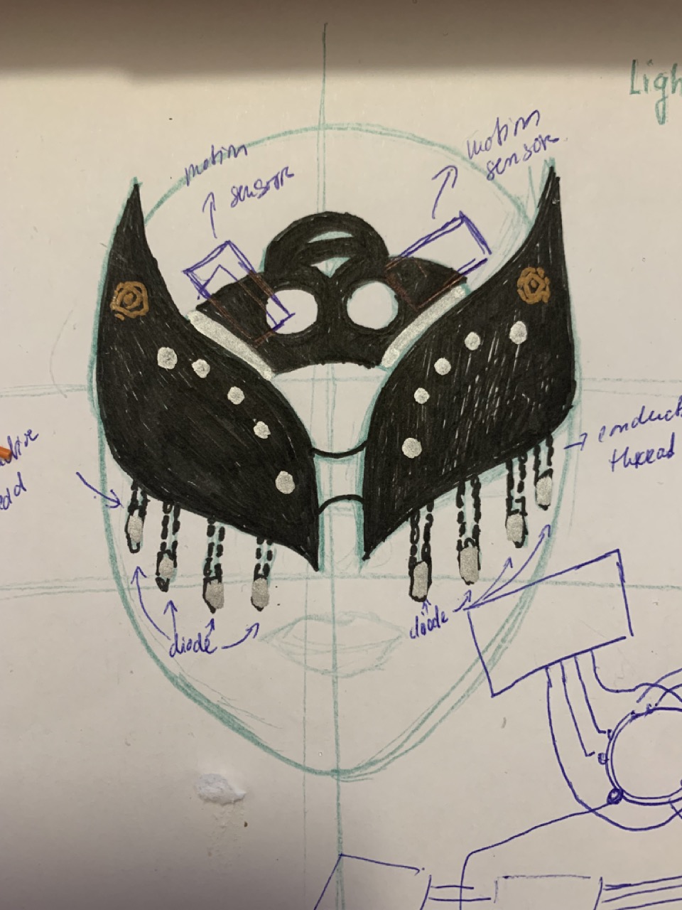
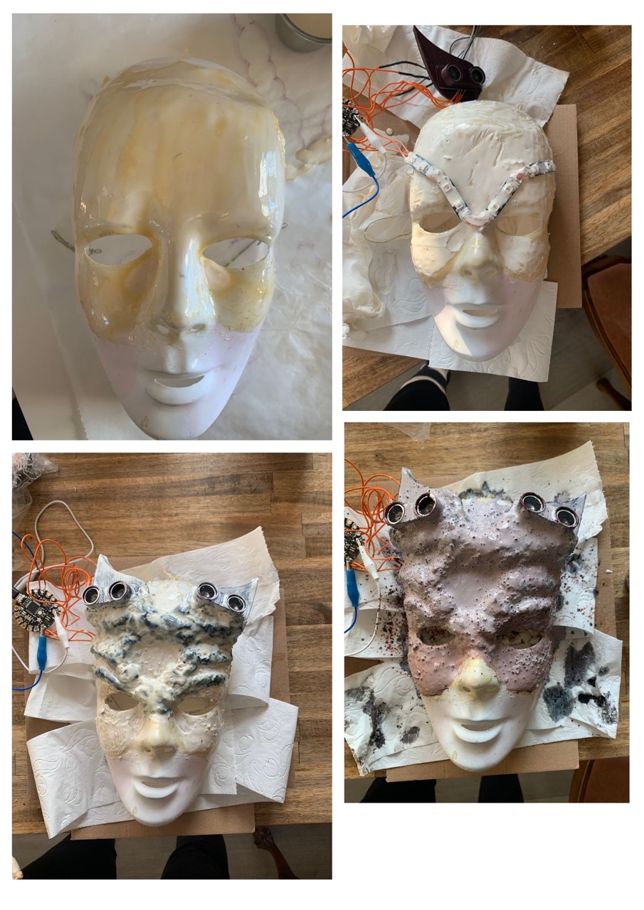
Mask
I have firstly sketched my idea.
List of Tools
- Mask - to cast on
- Latex
- Pinsel / Small Brush
- Play Dough
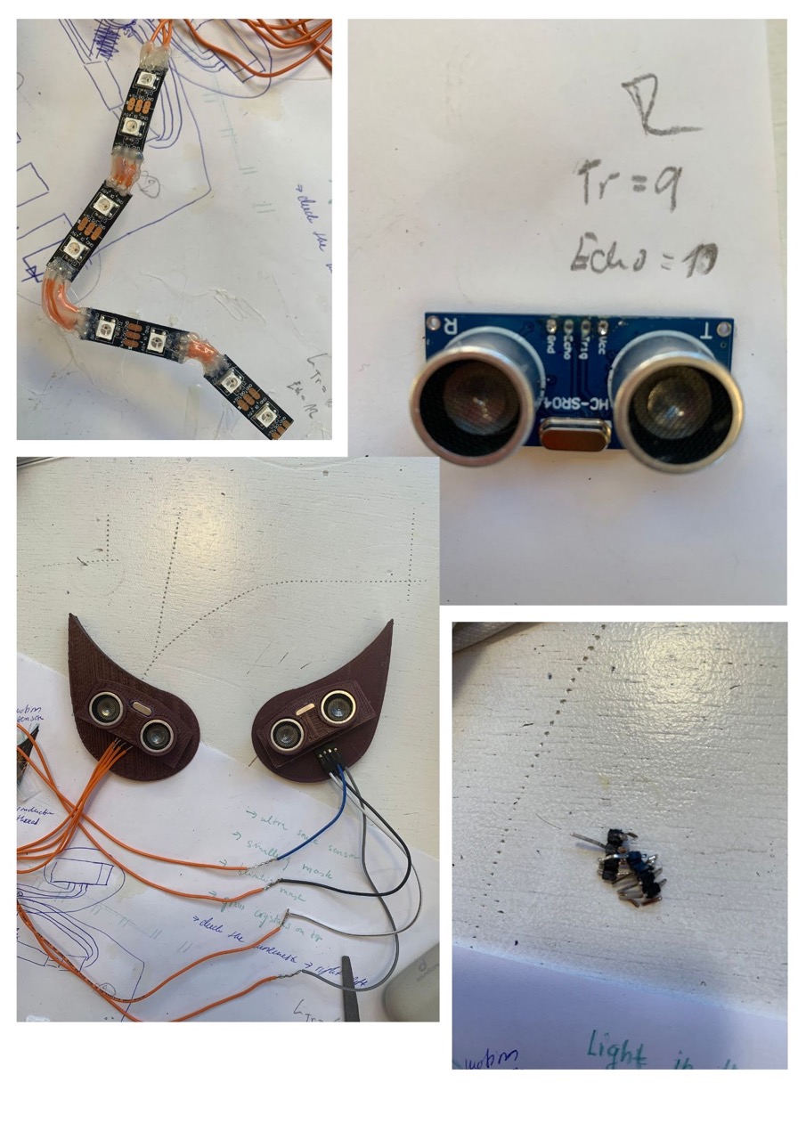
- Microcontroller with at least 8 PINS (Adafruit Flora)
- 8 RGB Neopixels LED
- 2 Ultrasonic sensors
- Wires
- Solder Iron + Soldering Tin
- Hot Glue Gun
- Shrinking Tubes
- Heat Gun (to shrink the tubes)
Starterd with Electronics
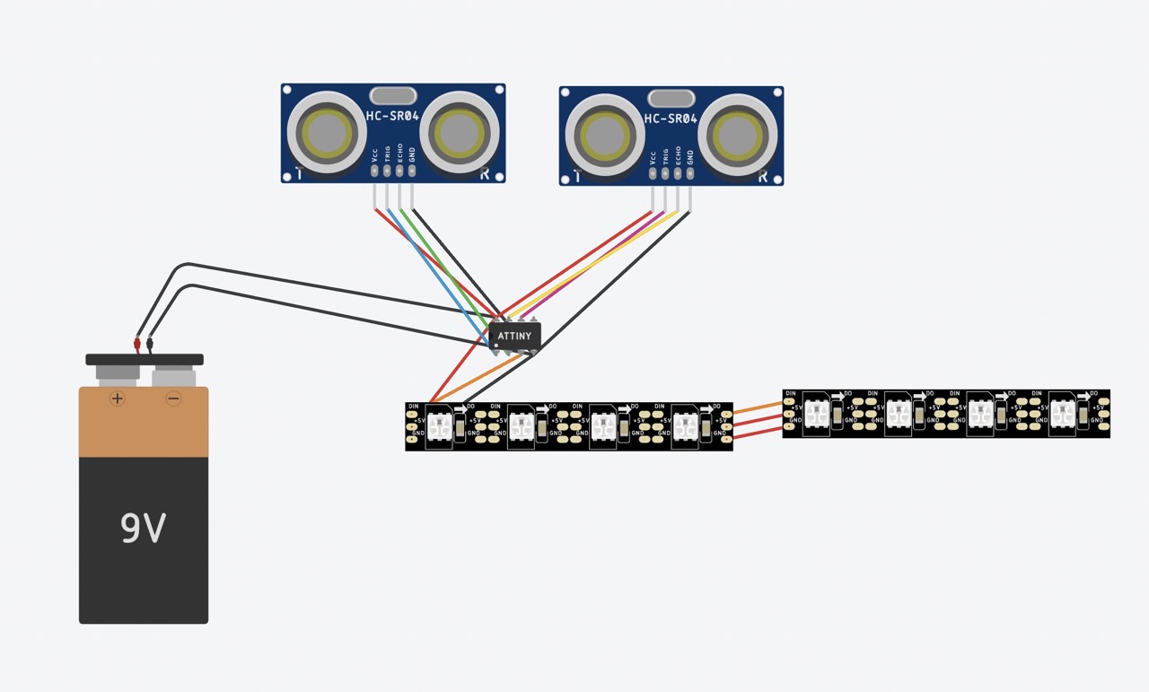
Website to understand better how ultrasonic sensors can detect movement.
Code Example
This code is the one that I have used for the Neopixels and the Ultrasonic Sensors. At first I had to troubleshoot a lot, because of the flow of the code. It is important to remember to write the code to firstly trigger and process one sensor and then the other one since it does not work when trying to trigger both and then process both.
#include <Adafruit_NeoPixel.h>

// Which pin on the Microcontroller is connected to the NeoPixels?
#define PIN            1

// How many NeoPixels are attached to it?
#define NUMPIXELS      8

// Declare our NeoPixel pixels object:
Adafruit_NeoPixel pixels = Adafruit_NeoPixel(NUMPIXELS, PIN, NEO_GRB + NEO_KHZ800);
//pack the color in one variable
uint32_t red = pixels.Color(255, 0, 0); //RGB
uint32_t blue = pixels.Color(0, 0, 255);
uint32_t green = pixels.Color(0, 255, 0);
uint32_t magenta = pixels.Color(255, 0, 255);
uint32_t off = pixels.Color(0, 0, 0);

//declare delay for passage of neopixels
int delayval = 20;

// set pins for ultrasonic sensors
#define trig_pin_1 6 // pin for sending sensor #1 trigger signal
#define echo_pin_1 12 // pin for receiving sensor #1 echo signal
#define trig_pin_2 9  // pin for sending sensor #2 trigger signal
#define echo_pin_2 10  // pin for receiving sensor #2 echo signal


// initialize variables
long d1;                  // sensor 1 distance
long d2;                  // sensor 2 distance
long t1;              // sensor 1 timestamp; initialize as 0
long t2;              // sensor 2 timestamp; initialize as 0
long time1 = 0;              // sensor 1 trigger timestamp; initialize as 0
long time2 = 0;              // sensor 2 trigger timestamp; initialize as 0
unsigned long start_time; // time since program start
float max_distance = 50;  // movement sensing range (in cm)

// function to calculate convert to centimeters
long microsecondsToCentimeters(long microseconds) {
  return microseconds / 29 / 2;
}

void setup() {
  pixels.begin(); // This initializes the NeoPixel library.
  pixels.show();            // Turn OFF all pixels ASAP
  pixels.setBrightness(64); //from 0 to 255, use it only in setup
  Serial.begin(9600);     // initialize serial monitor at 9,600 baud
  delay(2);            // pause
  start_time = millis();  // get program start time
  pinMode(trig_pin_1, OUTPUT); // Sets the trigPin as an Output
  pinMode(echo_pin_1, INPUT); // Sets the echoPin as an Input
  pinMode(trig_pin_2, OUTPUT); // Sets the trigPin as an Output
  pinMode(echo_pin_2, INPUT); // Sets the echoPin as an Input
}

void loop() {
  // Clears the trigPin
  digitalWrite(trig_pin_1, LOW);
  delayMicroseconds(2);
  // Sets the trigPin on HIGH state for 10 micro seconds
  digitalWrite(trig_pin_1, HIGH);
  delayMicroseconds(2);
  digitalWrite(trig_pin_1, LOW);

  // Reads the echoPin, returns the sound wave travel time in microseconds
  t1 = pulseIn(echo_pin_1, HIGH);
  d1 = microsecondsToCentimeters(t1);

  // Prints the distance on the Serial Monitor
  //Serial.print("Distance Left: ");
  //Serial.println(d1);


  delayMicroseconds(2);

  // Clears the trigPin
  digitalWrite(trig_pin_2, LOW);
  delayMicroseconds(2);
  // Sets the trigPin on HIGH state for 10 micro seconds
  digitalWrite(trig_pin_2, HIGH);
  delayMicroseconds(2);
  digitalWrite(trig_pin_2, LOW);

  // Reads the echoPin, returns the sound wave travel time in microseconds
  t2 = pulseIn(echo_pin_2, HIGH);
  d2 = microsecondsToCentimeters(t2);

  // Prints the distance on the Serial Monitor
  //Serial.print("Distance Right: ");
  //Serial.println(d2);


    // if either sensor distance drops below limit, record timestamp
    if (d1 < max_distance) {
      time1 = millis();
      Serial.println("Triggered Left");
    }
    else if (d2 < max_distance) {
      time2 = millis();
      Serial.println("Triggered Right");
    }

  if (time1 > 0 && time2 > 0) {       // if both sensors have nonzero timestamps
    if (time1 < time2) {                      // if left sensor triggered first
      Serial.println("Left to right");    // direction is left to right
        for(int i = 0;i <= NUMPIXELS;i++) {
        pixels.setPixelColor(i, blue); //set the color blue on the first pixel
        pixels.show();  //display the color
        delay(delayval * 3);

        pixels.setPixelColor(i, off); //set the color off
        pixels.show();  //display the color
        delay(delayval);
        }
    }
    else if (time2 < time1) {                 // if right sensor triggered first
      Serial.println("Right to left");    // direction is right to left
      for(int i = NUMPIXELS;i >= 0;i--) {
        pixels.setPixelColor(i, blue); //set the color blue on the first pixel
        pixels.show();  //display the color
        delay(delayval * 3);

        pixels.setPixelColor(i, off); //set the color off
        pixels.show();  //display the color
        delay(delayval);
        }
    }
    else {
      Serial.println("");         // else print nothing (shouldn't happen)
    }
    // after printing direction, reset both timestamps to 0
    time1 = 0;
    time2 = 0;
  }

}
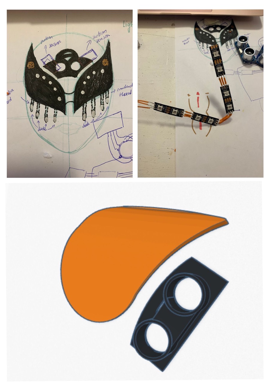
Creating the mask
TIP - I have accidentely left my brush in latex over night to find out the other day, that it works better when covered with latex. You can try to soak your brush, leave it for 30 minutes on the air. Clean it a bit and then use the brush again. It will help you to spread the latex evenly.
Results
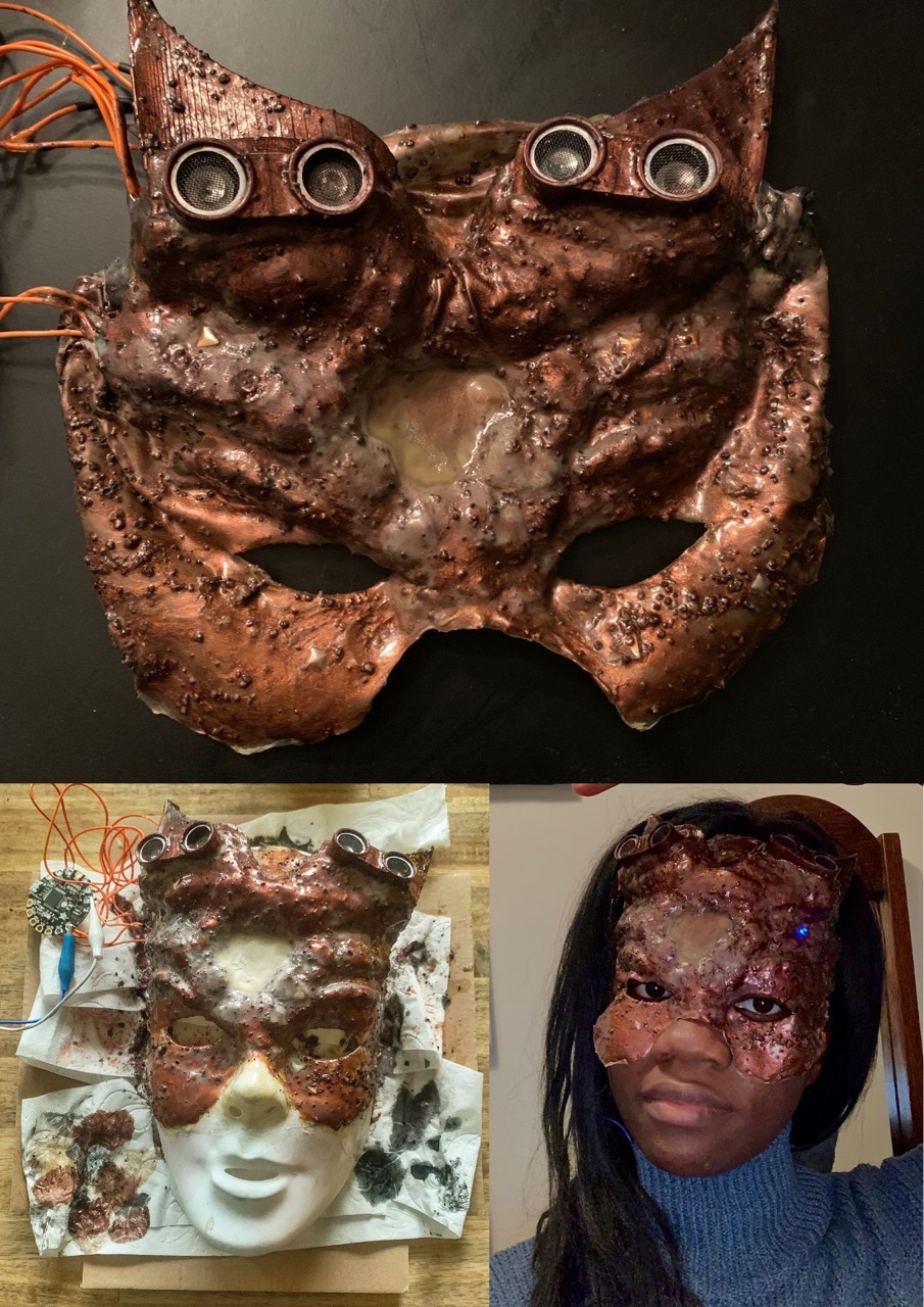
---
---
Fabrication files
-
File: STL File for the Horns ↩